EP1111182A2 - Dispositif pour étanchéifier un joint de bord d'un vitrage isolant encore ouvert dans une machine d'assemblage de tels vitrages - Google Patents
Dispositif pour étanchéifier un joint de bord d'un vitrage isolant encore ouvert dans une machine d'assemblage de tels vitrages Download PDFInfo
- Publication number
- EP1111182A2 EP1111182A2 EP00122103A EP00122103A EP1111182A2 EP 1111182 A2 EP1111182 A2 EP 1111182A2 EP 00122103 A EP00122103 A EP 00122103A EP 00122103 A EP00122103 A EP 00122103A EP 1111182 A2 EP1111182 A2 EP 1111182A2
- Authority
- EP
- European Patent Office
- Prior art keywords
- barrier
- plates
- glass
- axis
- plate
- Prior art date
- Legal status (The legal status is an assumption and is not a legal conclusion. Google has not performed a legal analysis and makes no representation as to the accuracy of the status listed.)
- Granted
Links
- 238000007789 sealing Methods 0.000 title claims abstract description 22
- 239000011521 glass Substances 0.000 claims abstract description 164
- 230000004888 barrier function Effects 0.000 claims abstract description 141
- 125000006850 spacer group Chemical group 0.000 claims abstract description 47
- 239000000463 material Substances 0.000 claims description 6
- 239000006263 elastomeric foam Substances 0.000 claims description 3
- 238000004519 manufacturing process Methods 0.000 claims description 3
- 239000000853 adhesive Substances 0.000 claims description 2
- 230000001070 adhesive effect Effects 0.000 claims description 2
- 239000013536 elastomeric material Substances 0.000 claims description 2
- 230000000717 retained effect Effects 0.000 claims 1
- 239000002184 metal Substances 0.000 description 5
- 229920001971 elastomer Polymers 0.000 description 3
- 239000006260 foam Substances 0.000 description 3
- 229920001169 thermoplastic Polymers 0.000 description 3
- 239000004416 thermosoftening plastic Substances 0.000 description 3
- 238000005452 bending Methods 0.000 description 2
- 239000000806 elastomer Substances 0.000 description 2
- 239000012815 thermoplastic material Substances 0.000 description 2
- 241000446313 Lamella Species 0.000 description 1
- 241000124008 Mammalia Species 0.000 description 1
- 229920002367 Polyisobutene Polymers 0.000 description 1
- 230000006978 adaptation Effects 0.000 description 1
- 230000000903 blocking effect Effects 0.000 description 1
- 229920005549 butyl rubber Polymers 0.000 description 1
- 238000000576 coating method Methods 0.000 description 1
- 210000001520 comb Anatomy 0.000 description 1
- 230000000295 complement effect Effects 0.000 description 1
- 230000001419 dependent effect Effects 0.000 description 1
- 238000011161 development Methods 0.000 description 1
- 230000018109 developmental process Effects 0.000 description 1
- 238000007598 dipping method Methods 0.000 description 1
- 238000006073 displacement reaction Methods 0.000 description 1
- 229920001821 foam rubber Polymers 0.000 description 1
- 238000011065 in-situ storage Methods 0.000 description 1
- 239000004033 plastic Substances 0.000 description 1
- 229920003023 plastic Polymers 0.000 description 1
- 229920002635 polyurethane Polymers 0.000 description 1
- 239000004814 polyurethane Substances 0.000 description 1
- 230000036316 preload Effects 0.000 description 1
- 239000005060 rubber Substances 0.000 description 1
- 239000003566 sealing material Substances 0.000 description 1
- 229920002050 silicone resin Polymers 0.000 description 1
- 210000001215 vagina Anatomy 0.000 description 1
Images


Classifications
-
- E—FIXED CONSTRUCTIONS
- E06—DOORS, WINDOWS, SHUTTERS, OR ROLLER BLINDS IN GENERAL; LADDERS
- E06B—FIXED OR MOVABLE CLOSURES FOR OPENINGS IN BUILDINGS, VEHICLES, FENCES OR LIKE ENCLOSURES IN GENERAL, e.g. DOORS, WINDOWS, BLINDS, GATES
- E06B3/00—Window sashes, door leaves, or like elements for closing wall or like openings; Layout of fixed or moving closures, e.g. windows in wall or like openings; Features of rigidly-mounted outer frames relating to the mounting of wing frames
- E06B3/66—Units comprising two or more parallel glass or like panes permanently secured together
- E06B3/677—Evacuating or filling the gap between the panes ; Equilibration of inside and outside pressure; Preventing condensation in the gap between the panes; Cleaning the gap between the panes
- E06B3/6775—Evacuating or filling the gap during assembly
Definitions
- the invention relates to a device with in the preamble of the claim 1 specified characteristics.
- a device is from EP 0 539 407 B1 known.
- EP 0 539 407 B1 discloses a device for assembling insulating glass panes, which are filled with a gas other than air.
- the device is a press with two mutually variable spacing, plates arranged approximately vertically, on which two glass plates, from which an insulating glass pane is to be formed, each other can be placed opposite one another.
- a horizontal conveyor provided that e.g. from a line of synchronously driven Rolls exist, the axes of which are perpendicular to the plates.
- a first glass panel on the roles of the Horizontal conveyor standing and against the first, fixed, about 6 ° after slanted rear plate transported into the device up to conveyed the edge of the plate on the outlet side and is flush with the outlet side Edge of the plate stopped.
- the first glass sheet is turned on by a lifting device little lifted from the horizontal conveyor and then from the second movable one Plate, which is designed as a suction plate, sucked from the first Plate removed and removed from it.
- One at the outlet side of the second plate provided strip of the second plate is formed so that it can be pivoted or bent away from the first plate and causes thus a corresponding bend in the glass sheet on the second plate is liable.
- the bar is attached to the movable plate and is between the position in which he the outlet-side edge of the two Plates rests, and an ineffective position in which he the insulating glass pane clears the way out of the space between the two plates, movable.
- a nozzle for feeding one Heavy gas is provided, which through the gap between the first Glass panel and the spacer in the interior of the still open insulating glass pane flows and displaces the air upwards from the interior.
- the first barrier on the bar Cover strip provided, which extends around a perpendicular to the plane of the plates Axis against the lower edges of the two plates and the glass panels can be pivoted, which are aligned.
- the cover strip is with a second barrier in the form of a brush, the bristles of which are inclined are directed upwards and at a point where the spacer connection to both glass panels, up to the spacer in the edge joint between immerse in the two glass panels and prevent heavy gas from entering the lower edge joint can flow along the spacer and is lost.
- the press is then opened and the insulating glass pane on the Horizontal conveyor conveyed out of the press.
- Step disks are common, in which the first Glass panel the second glass panel on at least one side, often on all sides protrudes up to 40 mm.
- a horizontal conveyor suitable for step discs is in EP 0 549 556 A1.
- EP 0 549 556 A1 does not disclose how to make such a stepped washer in an insulating glass press with heavy gas fill and can prevent the heavy gas through a gap at the bottom The edge of the insulating glass pane can flow out and be lost.
- the present invention has for its object to show a way how with step panes, which are to be filled with heavy gas in a device for assembling and pressing insulating glass panes, can be prevented by extending over part of one of the edges of the insulating glass pane wedge-shaped gap between the first glass sheet and the spacer, large amounts of heavy gas flow out and get lost.
- the device according to the invention like that known from EP 0 539 407 B1 Device for sealing an edge joint, in which a wedge-shaped gap there is a first barrier between the spacer and the first glass sheet, which on the edges of the two glass panels and / or can be attached to the two plates in the vicinity of the two glass plates, between which the insulating glass pane is assembled and with a Heavy gas is filled.
- the invention also has a second barrier, which at the starting point or behind the starting point of the wedge-shaped Gap at a point where the spacer lies against both glass panels, can be brought up to the spacer in the edge joint that the second barrier the edge joint divides transversely to its longitudinal direction.
- the second barrier exists in contrast to the solution disclosed in EP 0 539 407 B1 a brush with protruding diagonally upwards into the edge joint and against the spacer directed bristles, rather the second barrier consists of a plurality of extending parallel to the spacer, individually against a restoring force of flexible sections, especially from a brush.
- the Bristles or the like flexible sections are so long that the second barrier is wider than the distance between the two glass panels.
- To the second barrier in It is to be able to insert the full width into the edge joint of the insulating glass pane around a parallel to the plates and perpendicular to the spacer Axis rotatable.
- the bristles or the like stand from this axis bendable sections across, ideally at right angles to the axis.
- the second barrier can be in an orientation in which it faces the two panels runs parallel, inserted into the edge joint and then by rotating around it Axis to be brought into contact with the two glass panels.
- the bristles or Such flexible sections then block the entire cross section between the first, larger glass panel on one side and the opposite smaller glass panel and that opposite the larger glass panel Section of the plate on which the second glass sheet lies.
- the one by one flexible sections which are preferably the bristles of a flat brush, can infinitely vary in distances between both Glass panels as well as between the larger glass panel and the opposite one Adjust the plate and therefore for different distances from case to case an outflow of heavy gas along the spacer through the edge joint prevent the wedge-shaped gap. Also a stepless adjustment to different ones
- the invention allows joint depths; all that is required is that the brush is so long that it still has the greatest joint depth that occurs in practice can cover up. The brush is pushed up against the spacer advanced and then twisted, it ensures that it covers the entire cross section the edge joint can close, otherwise heavy gas along the Spacer could flow off.
- This ability of the second barrier to be stepless Adapting to different edge joints is important and advantageous because in the ongoing insulating glass production insulating glass panes with different Edge joints usually follow one another in a bundle.
- the axis is preferably displaceable transversely to the plates in one position which is closer to the first than the second glass sheet.
- The is advantageous when it comes to very small barriers with the same barrier Distances between the two glass panels, e.g. only 6 mm and also very large To be able to seal distances between the glass panels from 30 mm to 40 mm. If the axis can be moved across the plates, it is possible to always arrange the axis close to the first glass panel and for this purpose to couple with the plate to which the first glass sheet can be placed. To this This ensures that even with very small distances between the glass panels second barrier inserted into the edge joint and then by twisting around the Ache can be brought to the plant on the two glass panels.
- the axis depending on the changing thickness of the first glass panels can be moved into a position in which they takes up a constant small distance from the first glass sheet. It it is further preferred that the bristles from the axis in only one Direction or extend only into a narrow space segment and that at least as a result of the twisting of the second barrier, the axis with its the Bristle side facing the first glass sheet when the bristles of the smaller, second glass sheet.
- the axis is preferably a sealing tape extending along the axis provided in order to achieve the best possible seal.
- the sealing tape consists preferably of an elastomeric foam which is compressible and presses tightly against the first pane of glass.
- the sealing tape could be glued to the axle. However, it is cheaper to have two to provide axially parallel clamping plates, which both the axis and the Seal the sealing tape, preferably also the bristles between them.
- the sealing tape is preferably clamped between the two clamping plates in such a way that that it is deflected towards one of its sides by preload, and to the side to which the sealing tape is moved when the second Barrier is twisted to bring them to rest on the two glass panels. This ensures that the sealing tape is always adequate Acts on the first glass plate.
- a barrier with which from the axis of bristles in opposite directions, preferably Bristles longer in one direction than in the opposite direction.
- narrow elastomeric lamellas could also be used which protrude at right angles from the axis, e.g. Slats, which Base on the axis at an angle to the longitudinal direction and thereby overlap. Bristles which are combined to form a narrow brush are particularly preferred are.
- Such a brush can infinitely vary Adjust wide and different depth edge joints and make them sufficiently tight complete because the spaces between the bristles close, when the bristles hit the second glass plate by turning the brush and not only resiliently against them, but also against each other.
- the glass sheets are often sharp-edged and can damage the bristles.
- the brush is therefore preferably held interchangeably in the second barrier, best between the already mentioned clamping plates, which also Hold the sealing tape.
- the second barrier should be in the edge joint until it touches the spacer be introduced.
- Metallic hollow profile bars are used as spacers.
- thermoplastic spacers have also become used, which are extruded in situ on the second glass sheet. Such Thermoplastic spacers are when the glass panels are assembled and their interior is filled with heavy gas, not yet hardened.
- the spherical Surface consists of a material that is attached to the freshly extruded Spacer, not or only poorly adheres.
- Common materials for freshly extruded thermoplastic spacers are butyl rubbers (polyisobutylene) and polyurethane. Surfaces or surface coatings on which these The plastics specialist is aware of materials which adhere poorly or only poorly. Surfaces made of dusted silicone resin have proven their worth.
- the second barrier which is the flow of heavy gas along the spacer prevent, works with the first barrier, which one Prevent the heavy gas from flowing away transversely to the longitudinal direction of the spacer should.
- a bar or plate can be used as the first barrier similar to that which is also used for this purpose in EP 0 539 407 B1 is disclosed and is applied to the edge of the two plates.
- a complete one To enable the first and the second barrier to work together is the first barrier preferably divided into two sections, one section around the axis of the second barrier is rotatable and has a slot through which through which the second barrier can be advanced and retracted. The two sections the first barrier can overlap each other.
- a section of the first barrier is circular or to provide circular section-shaped cutout and therein the second, rotatable Arrange section of the first barrier. This way the second barrier penetrate the first barrier without gaps and provide an optimal seal of the Create edge joints in two directions.
- the sealing of the edge joint in the third direction namely in that of the second Barrier leading direction can be done as it is in EP 0 539 407 B1 is disclosed, namely by placing a bar in which a nozzle integrated for supplying heavy gas, on that adjacent edge of the insulating glass pane, at which the gap to the interior of the insulating glass pane on greatest is.
- the first barrier is expediently one that favors sealing elastomeric material coated, especially with a Vulkollan, which opposite the stress caused by the sharp-edged glass panel edges is sufficient is stable.
- the first barrier and the second barrier are preferably movable Plate of the assembly device is coupled and the first barrier is against the edge of the two panels swiveling, being with the first barrier at the same time the second barrier is pivoted.
- This pivotal movement will preferably carried out in two steps, the second step being small compared the first step is so that after the first step the first barrier is almost on the edge of the two plates. In this position, the second Barrier advanced against the spacer and twisted and only then the first barrier is moved completely against the edge of the two plates. On in this way the rotatable portion of the first barrier can be rotated, while it is still a short distance from the edge of the plates, so that its rotation is inhibited.
- the rotatable portion of the first barrier is preferred hingedly connected to the non-rotatable part of the first barrier, so that when the first barrier is pivoted, the direction of the axis of the second The barrier can remain intact, which is what drives the move second barrier relieved.
- a pinion and an in are particularly suitable for driving the second barrier the alignment of the axis of the second barrier arranged rack, which with the second barrier is coupled and with which the pinion meshes.
- the angle of rotation of the second barrier can be dependent on the distance of the two glass panels can be selected. Preferably, however, regardless of A fixed angle of rotation is maintained between the two glass sheets, which is preferable a fixed stop is provided, which is the angle of rotation of the second barrier limited. This is a particular advantage of using one narrow brush, the bristles of which can be bent to different degrees and in this way without changing the angle of rotation an adaptation to different Allow clearances between the glass panels.
- the third barrier makes it possible to remove the second barrier when manufacturing non-stepped insulating glass panes in their withdrawn, ineffective position, thereby the second barrier is spared and not replaced as often got to. But even without such a third barrier, the edge joint cannot stepped insulating glass pane sealed by advancing the second barrier become.
- the mode of operation of the device according to the invention does not depend on the orientation the plates of the assembly device.
- the two plates as it is mostly used today, almost vertical arranged.
- the invention is also applicable to assembly devices, in which the two plates are arranged horizontally and the insulating glass panes be assembled horizontally.
- the edge joint to be sealed lies with approximately vertical panels the wedge-shaped gap between the first glass sheet and the spacer expediently at the bottom of the two plates and the heavy gas is from the side, on the neighboring, leading from bottom to top, edge introduced into the space between the two glass panels, preferably near the bottom.
- the heavy gas then displaces from below the lighter air, which so to speak floating on the heavy gas upwards is pushed out. It is particularly important to ensure that the Heavy gas does not run out of the insulating glass pane at the lower edge thereof.
- the device for filling the heavy gas in the in EP 0 539 407 B1 disclosed device in the form of a bar or a bar on the Movable plate is attached, it is in the device according to the invention preferably on the fixed plate or on the frame of the assembly device attached and is used when assembling stepped insulating glass panes in the direction of the movable plate until it is joined by a seal running along the beam or bar on the first glass sheet strikes, which protrudes beyond the edge of the second plate, since it stepped insulating glass pane is larger than that lying against the first plate second glass panel.
- the device for filling is laid with a second seal of the heavy gas on the parallel edge of the first plate. Become in the assembly device, un-stepped insulating glass panes assembled, the device for filling the heavy gas with both of them mutually parallel seals on the outlet-side edges of the two plates on.
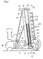
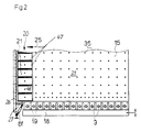
- Figures 1 and 2 show that the device has a base 1 and one Has base 2, which carries a horizontally conveying conveyor through a sequence of synchronously driven rollers 3 is formed. Between two adjacent rollers 3, a support 4 is arranged; the consequence of the support 4 is arranged on a lifting device designed as a walking beam 5, which extends to and is adjustable from, so that the support 4 between a position in which it protrude above the rollers 3, and a position in which they under the Top of the rollers 3 are sunk, can be moved back and forth.
- a lifting device designed as a walking beam 5 which extends to and is adjustable from
- a support wall 6 is arranged above the rollers 3, which on the one hand the base 2 and on the other hand by struts 7 and 8, which on the base 1 feet, in a back about 6 ° from the vertical inclined position is supported.
- the support wall 6 is designed as an air cushion wall. It has a first plate 9 in which a number of bores are distributed, which is supplied by a blower 10 via a line 11 compressed air.
- the front of the support wall 6 forms a first positioning surface 28 for a first Glass panel 40 and for a second glass panel 42.
- the rods 12 carry one at their front end Bracket 14, on which a frame is attached with a second plate 15, the runs parallel to the support wall 6 and by actuating the pressure medium cylinders 13 can be changed in their distance from the support wall 6.
- the second plate 15 is also designed as an air cushion wall and is therefore by another Line 17 connected to the blower 10. Like the support wall 6, it has its surface distributes a number of holes 35 through which the fan air can either exit or be sucked in. Your front forms a second positioning surface for the first glass sheet 40. Below the second Plate 15 is a further walking beam 18 with a number of supports 19 arranged.
- the outlet-side end of the second plate 15 with respect to the conveying direction is through a stripe-shaped, extending from the bottom to the top of the Plate 15 extending suction device 20 is formed, which consists of a number of there are suction cups 21 arranged one above the other, via pipes 22 and 23 are connected to a suction unit, not shown, and individually or can be activated in groups.
- the outlet end of the suction device 20 is aligned with the outlet-side edge of the first plate 9.
- a cover 26 provided, which in the conveyor path of the insulating glass panes and out the conveyor path can be moved out.
- the suction device 20 comprises a sheet 50, which together with the remaining plate 15 a glass sheet 40 to be bent by suction holds on.
- the sheet 50 extends from the lower edge to the upper edge the plate 15, which is rigid at its outlet-side edge with a metal plate 51 is connected, the front of which is opposite to the front of the second plate 15 is set back.
- the sheet 50 is fixed to the front of the metal plate 51 connected and protrudes in the conveying direction 25 beyond the metal plate 51; the Sheet 50 is in this way by one-sided clamping on the outlet side Edge of the rigid portion of the second plate 15 attached.
- the sheet 50 can be clamped transversely to its surface by elastic Bending be deflected.
- a hinge 52 articulated a plate 53, which on the back by struts 54 and 55, which are at right angles run to the surface of the plate 53, connected to a further plate 56 so that the plates 53 and 56 form a frame with the struts 54 and 55, which is parallel to itself and to the front surface of the plate 15 and can be moved back.
- the frame is guided in parallel by a four-bar link ensures which by the clamping point of the sheet 50 the metal plate 51, by the hinge 52 and by two in a corresponding Joints 57 and 58 which are arranged at a distance and are located behind the plate 56 , of which the joint 57 is fixed to the plate 56 and the joint 58 is fixed is connected to the base frame of the second plate 15, the two joints 57 and 58 are interconnected by a link 60.
- the mechanism for moving the frame 53 to 56 comprises two inflatable ones Hoses 61 and 62.
- the hose 61 is between the plate 53 and the front of a column 63 running between the plates 53 and 56, which belongs to the base frame 59 and is thus fixed to the frame.
- the Hose 62 is between plate 56 and the back of column 63 arranged.
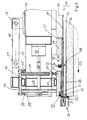
- the rear tube 62 is inflated and the front tube 61 is vented ( Figure 3), then the plate 53 is retracted until it is adjustable Stop 64 hits against the base frame 59. With the plate 53 moves outlet-side edge of the sheet 50 back, which is thereby bent. If both hoses 61 and 62 are vented, the plate 50 returns through elastic Spring back to its starting position, in which it is coated with its Front is in alignment with the positioning surface 29. Will be complementary the front tube 61 is inflated, then the sheet 50 is in place stabilized with adjustable stops provided on the rear plate 56 65, which abut the base frame 59, ensure that the suction device 20 not pushed forward with their front side beyond the positioning surface 29 becomes.
- the front of the sheet 50 is coated with a layer 66 of an elastomer Material, in particular made of rubber, provided for subdivision and limitation the individual suction cups 21 strip-shaped, compressible seals, e.g. B. made of foam rubber, are embedded in the layer 66.
- These stripe-shaped Seals 67 give each sucker a rectangular outline shape in the middle there is a suction opening 68 (FIG. 2).
- the strip-shaped seals 67 are over the front of the layer 66 and when sucking in the first Glass plate 40 compressed.
- the glass plate 40 sucked thereon is also bent, which is in an insulating glass pane 44, which is between the first Plate 9 and the second plate 15, forms a gap-shaped opening 43, which lies on the outlet-side edge of the insulating glass pane 44 (see FIG. 3).
- a gas other than air in particular a heavy gas, is blown in and the air is displaced from the interior.
- a nozzle 31 is provided ( Figure 10 and Figure 12), which in the Neighborhood of the lower corner of the insulating glass pane 44 on its outlet side Edge is brought to the plant.
- the nozzle 31 is located on an elongated one Angle rail 32, which is part of the cover element 26, to cover the entire outlet-side edge of the insulating glass pane 44 serves and is movably attached to the support wall 6.
- the vertical columnar Opening 43 sits at the top and bottom of the glass panels 40, 42 in a wedge-shaped gap 24 continues (see Figure 10).
- a first is pivotable on the second plate 15 plate-shaped barrier 27 is provided, which has a support on its top 98 from a resilient sealing material and to the bottom edge of the two plates 9 and 15 and optionally the insulating glass pane 44 is (see Figures 2, 9 and 11). This is said to be along the wedge-shaped gap 24, which forms when bending the glass plate 40 at the bottom, the lower edge joint 45 of the insulating glass pane to be sealed towards the bottom.
- the first barrier 27 is around a horizontal one Axle 70 pivotally attached to a support 71, which in turn with With the help of two horizontal guide rods 72 and 73 on the movable one Plate 15 of the assembly and pressing device attached and using a horizontal pneumatic cylinder 74 relative to the surface of the movable Plate 15 is slidable.
- the first barrier 27 has a first section 75, which is pivotably mounted on the carrier 71 about the axis 70 and has a second section 76 in the form of a circular plate, which around a vertical axis 77 is pivotally attached to a support 78 which pivotable about a horizontal axis 79 on the first section 75 is appropriate.
- the axes 70 and 79 run parallel to one another.
- the carrier 78 is not only by means of the first section 75 of the first barrier 27, but also connected to the supports 71 by means of a parallel link 80, so that the beams 71 and 78, the section 75 and the handlebar 80 a Form quadrilateral, which a parallel displacement of the carrier 78 and enable with him the second section 76 of the first barrier, for which the Carrier 71 and carrier 78 are connected to one another by a pneumatic cylinder 81 are.
- the pneumatic cylinder 81 is eccentric on a pin 82 stored, which is rotatably supported in the carrier 71 and by a pneumatic Cylinder 83 can be pivoted.
- the second barrier has two clamping plates 87 and 88, which are screwed together 89 held together and a flat brush between them 90 and on the other hand clamp an elastomeric foam strip 91, which by clamping a bar 92 in one facing away from the bar 92 Direction is biased.
- the second barrier 38 is narrow in the sheath 84 guided and is arranged so that it with the screws 89 on the axis 77th lies about which the second section 76 of the first barrier 27 is rotatable.
- the Rotary movement is effected by a pneumatic cylinder 93 and has two end positions, one of which is shown in FIG. 4 and is determined thereby, that the pneumatic cylinder 93 is completely retracted. The other end position results differs in that the rotatable portion 76 with a on its underside provided projection 94 strikes a cam 95 which on the fixed Support wall 6 of the device is attached.
- a third barrier 96 is provided, which is a flat brush is which extends transversely to the sheath 84 and the bristles obliquely upward from the surface of the rotatable portion 76 of the first Barrier 27 emerge.
- the lower edge joint 45 is according to the invention sealed as follows:
- the two glass panels 40, 42 are between the plates 9 and 15 of the assembly and pressing device arranged as shown in Figures 9 to 12 is:
- the larger first glass sheet 40 is positioned so that its lower Edge flush with the lower edge of the movable plate 15 ( Figure 9) and that its outlet side vertical edge over the vertical edge of the plate 15 protrudes ( Figure 10).
- the smaller, second glass sheet 42 is positioned that its lower edge above the lower edge of the fixed plate 9 of the device is arranged ( Figure 9), whereas its outlet-side, vertical edge ends flush with the outlet-side, vertical edge of the fixed plate 9 ( Figure 10).
- the height of the glass panels 40 and 42 is determined by the two sides Walking beam 5 and 18 (see Figure 1) determined.
- the first barrier 27 depending on the thickness the first glass sheet 40 positioned so that the vertical axis 77 in one for all Use cases same small distance in front of the inner surface of the first glass sheet 40 is located ( Figure 9, Figure 10). Then by actuating the pneumatic cylinder 81 raised the first barrier 27 and out of the one shown in FIG bent shape into the stretched shape shown in Figure 6 transferred. In this position, the first barrier 27 is still a short distance away of the two plates 9 and 15, as shown in FIG. By advancing the rack 86 then becomes the second barrier 38 with the one in FIG.
- the brush 90 is parallel to the glass panels 40 and 42 extends, pushed up to the spacer 41.
- the second barrier 38 is crowned in the region of its axis 77 Provide head 97, which consists of a material on which the thermoplastic Material of the spacer 41 is not liable. Then the rotatable Section 76 of the first barrier 27 by actuating the pneumatic cylinder 93 twisted about axis 77.
- the second barrier 38 seals the lower one Edge joint at a point beyond the starting point 99 of the wedge-shaped Gap 24 is down to the inlet side of the assembly and pressing device.
- the edge joint 45 is sealed by the Cover element 26 with a first vertically extending seal 100 against the first glass sheet 40 and with a second vertically extending seal 101 against the fixed plate 9 is placed, creating the vertical edge of the still open insulating glass pane is sealed.
- a nozzle 31 is provided which carries heavy gas through the gap 43 between the first glass sheet 40 and the spacer 41 in the space can flow between the two glass panels 40 and 42 and the therein air initially displaced upwards.
- the first barrier 27 and the second barrier 38 together ensure that the heavy gas cannot flow downwards out of the still open insulating glass pane and gets lost. Once the desired amount of heavy gas has been filled in, the bend the plate 15 undone and thereby the column 24 and 45 between the first glass sheet 40 and the spacer 41 are closed.
Landscapes
- Engineering & Computer Science (AREA)
- Civil Engineering (AREA)
- Structural Engineering (AREA)
- Securing Of Glass Panes Or The Like (AREA)
Applications Claiming Priority (2)
| Application Number | Priority Date | Filing Date | Title |
|---|---|---|---|
| DE19962034A DE19962034C1 (de) | 1999-12-22 | 1999-12-22 | Einrichtung zum Abdichten einer Randfuge einer noch nicht geschlosenen Isolierglasscheibe an einer Vorrichtung zum Zusammenbauen von Isolierglasscheiben |
| DE19962034 | 1999-12-22 |
Publications (3)
| Publication Number | Publication Date |
|---|---|
| EP1111182A2 true EP1111182A2 (fr) | 2001-06-27 |
| EP1111182A3 EP1111182A3 (fr) | 2002-09-25 |
| EP1111182B1 EP1111182B1 (fr) | 2005-01-19 |
Family
ID=7933828
Family Applications (1)
| Application Number | Title | Priority Date | Filing Date |
|---|---|---|---|
| EP00122103A Expired - Lifetime EP1111182B1 (fr) | 1999-12-22 | 2000-10-12 | Dispositif pour assembler des vitrages isolantes avec des moyens pour étanchéifier un joint de bord d'un vitrage isolant encore ouvert |
Country Status (3)
| Country | Link |
|---|---|
| EP (1) | EP1111182B1 (fr) |
| AT (1) | ATE287488T1 (fr) |
| DE (2) | DE19962034C1 (fr) |
Families Citing this family (3)
| Publication number | Priority date | Publication date | Assignee | Title |
|---|---|---|---|---|
| DE102004032604B4 (de) * | 2004-07-06 | 2006-05-18 | Lenhardt Maschinenbau Gmbh | Verfahren und Vorrichtung zum Zusammenbauen eines Solarzellenmoduls |
| ITTO20120076A1 (it) * | 2012-01-30 | 2013-07-31 | Bottero Ig S R L | Metodo e macchina per la formatura di un vetro camera |
| CN116698908B (zh) * | 2023-06-02 | 2024-03-19 | 南京方正建设工程质量检测有限公司 | 幕墙玻璃隔热性能试验室检测装置 |
Citations (2)
| Publication number | Priority date | Publication date | Assignee | Title |
|---|---|---|---|---|
| EP0549556A1 (fr) | 1991-12-23 | 1993-06-30 | Peter Lisec | Dispositif pour convoyer des plaques de verre isolantes |
| EP0539407B1 (fr) | 1990-07-13 | 1994-08-10 | Lenhardt Maschinenbau GmbH | Procede et dispositif d'assemblage de vitres isolantes remplies d'un gaz autre que l'air |
Family Cites Families (2)
| Publication number | Priority date | Publication date | Assignee | Title |
|---|---|---|---|---|
| DE3101342C2 (de) * | 1981-01-17 | 1984-08-02 | Vereinigte Glaswerke Gmbh, 5100 Aachen | "Verfahren zur Herstellung von gasgefüllten Isolierglaseinheiten und Vorrichtung zur Durchführung des Verfahrens" |
| DE29922490U1 (de) * | 1999-12-22 | 2000-04-06 | Lenhardt Maschinenbau GmbH, 75242 Neuhausen | Einrichtung zum Abdichten einer Randfuge einer noch nicht geschlossenen Isolierglasscheibe an einer Vorrichtung zum Zusammenbauen von Isolierglasscheiben |
-
1999
- 1999-12-22 DE DE19962034A patent/DE19962034C1/de not_active Expired - Fee Related
-
2000
- 2000-10-12 DE DE50009274T patent/DE50009274D1/de not_active Expired - Lifetime
- 2000-10-12 EP EP00122103A patent/EP1111182B1/fr not_active Expired - Lifetime
- 2000-10-12 AT AT00122103T patent/ATE287488T1/de active
Patent Citations (2)
| Publication number | Priority date | Publication date | Assignee | Title |
|---|---|---|---|---|
| EP0539407B1 (fr) | 1990-07-13 | 1994-08-10 | Lenhardt Maschinenbau GmbH | Procede et dispositif d'assemblage de vitres isolantes remplies d'un gaz autre que l'air |
| EP0549556A1 (fr) | 1991-12-23 | 1993-06-30 | Peter Lisec | Dispositif pour convoyer des plaques de verre isolantes |
Also Published As
| Publication number | Publication date |
|---|---|
| ATE287488T1 (de) | 2005-02-15 |
| EP1111182B1 (fr) | 2005-01-19 |
| DE19962034C1 (de) | 2001-03-22 |
| DE50009274D1 (de) | 2005-02-24 |
| EP1111182A3 (fr) | 2002-09-25 |
Similar Documents
| Publication | Publication Date | Title |
|---|---|---|
| EP0539407B1 (fr) | Procede et dispositif d'assemblage de vitres isolantes remplies d'un gaz autre que l'air | |
| EP0674087B1 (fr) | Dispositif de fabrication de vitrages isolants remplis de gaz lourd | |
| EP0406325B1 (fr) | Procede et dispositif pour remplir des vitres isolantes de gaz lourd | |
| DE102010035748B4 (de) | Verfahren zum Zusammenbauen von Isolierglasscheiben, die drei zueinander parallele Glasplatten haben | |
| DE102009048642B4 (de) | Vorrichtung zum Zusammenbauen eines Fensterflügels mit integrierter Isolierglasscheibe | |
| AT412719B (de) | Verfahren und vorrichtung zum bereichsweisen entschichten von glasscheiben | |
| AT396782B (de) | Vorrichtung zum fördern von gegenüber der lotrechten etwas geneigten isolierglasscheiben | |
| DE102009048641B4 (de) | Verfahren zum Zusammenbauen eines Fensterflügels mit integrierter Isolierglasscheibe | |
| EP0902150B1 (fr) | Méthode pour le revêtement de cadres d'espacement pour vitrages isolants | |
| EP0308393B1 (fr) | Dispositif pour le bouchage des ouvertures dans des éléments d'espacement | |
| DE4231424C2 (de) | Verfahren und Vorrichtung zum Zusammenbauen von Isolierglasscheiben, deren Glastafeln durch einen plastischen Abstandhalter auf Abstand gehalten und miteinander verklebt sind | |
| DE102005044861B3 (de) | Verfahren und Vorrichtung zum Füllen von Isolierglasscheiben mit einem von Luft verschiedenen Gas | |
| WO2006002975A1 (fr) | Procede et dispositif de montage de vitres isolantes remplies d'un gaz autre que l'air | |
| DE19962034C1 (de) | Einrichtung zum Abdichten einer Randfuge einer noch nicht geschlosenen Isolierglasscheibe an einer Vorrichtung zum Zusammenbauen von Isolierglasscheiben | |
| DE29922490U1 (de) | Einrichtung zum Abdichten einer Randfuge einer noch nicht geschlossenen Isolierglasscheibe an einer Vorrichtung zum Zusammenbauen von Isolierglasscheiben | |
| EP2007962A1 (fr) | Dispositif pour assembler des vitres de verre isolantes qui sont remplies d'un gaz différent de l'air | |
| DE3914706A1 (de) | Verfahren und vorrichtung zum zusammenbauen von isolierglasscheiben, die mit einem von luft verschiedenen gas gefuellt sind | |
| DE69831157T2 (de) | Handwerkszeug zum auftragen von dichtstreifen | |
| DE4335671A1 (de) | Verfahren und Vorrichtung zum Zusammenbauen von Isolierglasscheiben mit rahmenförmigen Abstandhaltern aus einer plastischen Masse | |
| DE4212256C2 (de) | Vorrichtung zum Zusammenbauen von zwei Isolierglasscheiben die mit einem von Luft verschiedenen Gas gefüllt sind | |
| DE4404029A1 (de) | Verfahren und Vorrichtung zum Zusammenbauen von Isolierglasscheiben mit rahmenförmigen Abstandhaltern aus einer plastischen Masse | |
| DE9205069U1 (de) | Vorrichtung zum Zusammenbauen von zwei Isolierglasscheiben die mit einem von Luft verschiedenen Gas gefüllt sind | |
| DE202010007183U1 (de) | Vorrichtung zum Zusammenbauen eines Fensterflügels mit integrierter Isolierglasscheibe | |
| DE102024120653A1 (de) | Einrichtung und Verfahren zum unabhängigen Transportieren von zwei Glasscheiben in einer Scheibenbearbeitungsvorrichtung | |
| DE1679961C (de) | Vorrichtung zum Wölben einer sich in plastischem Zustand befindenden Platte mit einer Wölbeform |
Legal Events
| Date | Code | Title | Description |
|---|---|---|---|
| PUAI | Public reference made under article 153(3) epc to a published international application that has entered the european phase |
Free format text: ORIGINAL CODE: 0009012 |
|
| AK | Designated contracting states |
Kind code of ref document: A2 Designated state(s): AT BE CH CY DE DK ES FI FR GB GR IE IT LI LU MC NL PT SE |
|
| AX | Request for extension of the european patent |
Free format text: AL;LT;LV;MK;RO;SI |
|
| PUAL | Search report despatched |
Free format text: ORIGINAL CODE: 0009013 |
|
| AK | Designated contracting states |
Kind code of ref document: A3 Designated state(s): AT BE CH CY DE DK ES FI FR GB GR IE IT LI LU MC NL PT SE |
|
| AX | Request for extension of the european patent |
Free format text: AL;LT;LV;MK;RO;SI |
|
| 17P | Request for examination filed |
Effective date: 20020928 |
|
| AKX | Designation fees paid |
Designated state(s): AT BE CH CY DE DK ES FI FR GB GR IE IT LI LU MC NL PT SE |
|
| 17Q | First examination report despatched |
Effective date: 20031201 |
|
| GRAP | Despatch of communication of intention to grant a patent |
Free format text: ORIGINAL CODE: EPIDOSNIGR1 |
|
| RTI1 | Title (correction) |
Free format text: DEVICE ASSEMBLING AN INSULATING GLAZING PANEL WITH MEANS FOR SEALING AN EDGE JOINT OF A STILL OPEN INSULATING GLAZING PAN |
|
| GRAS | Grant fee paid |
Free format text: ORIGINAL CODE: EPIDOSNIGR3 |
|
| GRAA | (expected) grant |
Free format text: ORIGINAL CODE: 0009210 |
|
| AK | Designated contracting states |
Kind code of ref document: B1 Designated state(s): AT BE CH CY DE DK ES FI FR GB GR IE IT LI LU MC NL PT SE |
|
| PG25 | Lapsed in a contracting state [announced via postgrant information from national office to epo] |
Ref country code: FI Free format text: LAPSE BECAUSE OF FAILURE TO SUBMIT A TRANSLATION OF THE DESCRIPTION OR TO PAY THE FEE WITHIN THE PRESCRIBED TIME-LIMIT Effective date: 20050119 Ref country code: IE Free format text: LAPSE BECAUSE OF FAILURE TO SUBMIT A TRANSLATION OF THE DESCRIPTION OR TO PAY THE FEE WITHIN THE PRESCRIBED TIME-LIMIT Effective date: 20050119 |
|
| REG | Reference to a national code |
Ref country code: GB Ref legal event code: FG4D Free format text: NOT ENGLISH |
|
| REG | Reference to a national code |
Ref country code: CH Ref legal event code: EP |
|
| REG | Reference to a national code |
Ref country code: IE Ref legal event code: FG4D Free format text: GERMAN |
|
| REF | Corresponds to: |
Ref document number: 50009274 Country of ref document: DE Date of ref document: 20050224 Kind code of ref document: P |
|
| PG25 | Lapsed in a contracting state [announced via postgrant information from national office to epo] |
Ref country code: SE Free format text: LAPSE BECAUSE OF FAILURE TO SUBMIT A TRANSLATION OF THE DESCRIPTION OR TO PAY THE FEE WITHIN THE PRESCRIBED TIME-LIMIT Effective date: 20050419 Ref country code: DK Free format text: LAPSE BECAUSE OF FAILURE TO SUBMIT A TRANSLATION OF THE DESCRIPTION OR TO PAY THE FEE WITHIN THE PRESCRIBED TIME-LIMIT Effective date: 20050419 Ref country code: GR Free format text: LAPSE BECAUSE OF FAILURE TO SUBMIT A TRANSLATION OF THE DESCRIPTION OR TO PAY THE FEE WITHIN THE PRESCRIBED TIME-LIMIT Effective date: 20050419 |
|
| PG25 | Lapsed in a contracting state [announced via postgrant information from national office to epo] |
Ref country code: ES Free format text: LAPSE BECAUSE OF FAILURE TO SUBMIT A TRANSLATION OF THE DESCRIPTION OR TO PAY THE FEE WITHIN THE PRESCRIBED TIME-LIMIT Effective date: 20050430 |
|
| GBT | Gb: translation of ep patent filed (gb section 77(6)(a)/1977) |
Effective date: 20050427 |
|
| REG | Reference to a national code |
Ref country code: IE Ref legal event code: FD4D |
|
| PG25 | Lapsed in a contracting state [announced via postgrant information from national office to epo] |
Ref country code: CY Free format text: LAPSE BECAUSE OF FAILURE TO SUBMIT A TRANSLATION OF THE DESCRIPTION OR TO PAY THE FEE WITHIN THE PRESCRIBED TIME-LIMIT Effective date: 20051012 |
|
| PG25 | Lapsed in a contracting state [announced via postgrant information from national office to epo] |
Ref country code: MC Free format text: LAPSE BECAUSE OF NON-PAYMENT OF DUE FEES Effective date: 20051031 Ref country code: LI Free format text: LAPSE BECAUSE OF NON-PAYMENT OF DUE FEES Effective date: 20051031 Ref country code: CH Free format text: LAPSE BECAUSE OF NON-PAYMENT OF DUE FEES Effective date: 20051031 Ref country code: LU Free format text: LAPSE BECAUSE OF NON-PAYMENT OF DUE FEES Effective date: 20051031 |
|
| PLBE | No opposition filed within time limit |
Free format text: ORIGINAL CODE: 0009261 |
|
| STAA | Information on the status of an ep patent application or granted ep patent |
Free format text: STATUS: NO OPPOSITION FILED WITHIN TIME LIMIT |
|
| ET | Fr: translation filed | ||
| 26N | No opposition filed |
Effective date: 20051020 |
|
| REG | Reference to a national code |
Ref country code: CH Ref legal event code: PL |
|
| PG25 | Lapsed in a contracting state [announced via postgrant information from national office to epo] |
Ref country code: PT Free format text: LAPSE BECAUSE OF NON-PAYMENT OF DUE FEES Effective date: 20050619 |
|
| REG | Reference to a national code |
Ref country code: FR Ref legal event code: PLFP Year of fee payment: 16 |
|
| REG | Reference to a national code |
Ref country code: FR Ref legal event code: PLFP Year of fee payment: 17 |
|
| PGFP | Annual fee paid to national office [announced via postgrant information from national office to epo] |
Ref country code: NL Payment date: 20161025 Year of fee payment: 17 Ref country code: GB Payment date: 20161025 Year of fee payment: 17 |
|
| PGFP | Annual fee paid to national office [announced via postgrant information from national office to epo] |
Ref country code: BE Payment date: 20161025 Year of fee payment: 17 |
|
| REG | Reference to a national code |
Ref country code: FR Ref legal event code: PLFP Year of fee payment: 18 |
|
| PGFP | Annual fee paid to national office [announced via postgrant information from national office to epo] |
Ref country code: FR Payment date: 20171023 Year of fee payment: 18 Ref country code: DE Payment date: 20171005 Year of fee payment: 18 |
|
| PGFP | Annual fee paid to national office [announced via postgrant information from national office to epo] |
Ref country code: IT Payment date: 20171020 Year of fee payment: 18 Ref country code: AT Payment date: 20171018 Year of fee payment: 18 |
|
| REG | Reference to a national code |
Ref country code: NL Ref legal event code: MM Effective date: 20171101 |
|
| GBPC | Gb: european patent ceased through non-payment of renewal fee |
Effective date: 20171012 |
|
| PG25 | Lapsed in a contracting state [announced via postgrant information from national office to epo] |
Ref country code: GB Free format text: LAPSE BECAUSE OF NON-PAYMENT OF DUE FEES Effective date: 20171012 Ref country code: NL Free format text: LAPSE BECAUSE OF NON-PAYMENT OF DUE FEES Effective date: 20171101 |
|
| REG | Reference to a national code |
Ref country code: BE Ref legal event code: MM Effective date: 20171031 |
|
| PG25 | Lapsed in a contracting state [announced via postgrant information from national office to epo] |
Ref country code: BE Free format text: LAPSE BECAUSE OF NON-PAYMENT OF DUE FEES Effective date: 20171031 |
|
| REG | Reference to a national code |
Ref country code: DE Ref legal event code: R119 Ref document number: 50009274 Country of ref document: DE |
|
| REG | Reference to a national code |
Ref country code: AT Ref legal event code: MM01 Ref document number: 287488 Country of ref document: AT Kind code of ref document: T Effective date: 20181012 |
|
| PG25 | Lapsed in a contracting state [announced via postgrant information from national office to epo] |
Ref country code: DE Free format text: LAPSE BECAUSE OF NON-PAYMENT OF DUE FEES Effective date: 20190501 |
|
| PG25 | Lapsed in a contracting state [announced via postgrant information from national office to epo] |
Ref country code: FR Free format text: LAPSE BECAUSE OF NON-PAYMENT OF DUE FEES Effective date: 20181031 |
|
| PG25 | Lapsed in a contracting state [announced via postgrant information from national office to epo] |
Ref country code: AT Free format text: LAPSE BECAUSE OF NON-PAYMENT OF DUE FEES Effective date: 20181012 Ref country code: IT Free format text: LAPSE BECAUSE OF NON-PAYMENT OF DUE FEES Effective date: 20181012 |