EP1111196A2 - Système d'aubes de guidage variables pour la turbine d'une turbosoufflante - Google Patents
Système d'aubes de guidage variables pour la turbine d'une turbosoufflante Download PDFInfo
- Publication number
- EP1111196A2 EP1111196A2 EP00106218A EP00106218A EP1111196A2 EP 1111196 A2 EP1111196 A2 EP 1111196A2 EP 00106218 A EP00106218 A EP 00106218A EP 00106218 A EP00106218 A EP 00106218A EP 1111196 A2 EP1111196 A2 EP 1111196A2
- Authority
- EP
- European Patent Office
- Prior art keywords
- exhaust gas
- gas turbine
- guide vane
- turbine according
- guide
- Prior art date
- Legal status (The legal status is an assumption and is not a legal conclusion. Google has not performed a legal analysis and makes no representation as to the accuracy of the status listed.)
- Granted
Links
- 238000013016 damping Methods 0.000 claims description 9
- 238000002485 combustion reaction Methods 0.000 claims description 7
- 230000000903 blocking effect Effects 0.000 claims 1
- 238000007789 sealing Methods 0.000 description 8
- 230000001133 acceleration Effects 0.000 description 3
- 230000006866 deterioration Effects 0.000 description 3
- 230000008901 benefit Effects 0.000 description 2
- 230000001419 dependent effect Effects 0.000 description 2
- 230000006872 improvement Effects 0.000 description 2
- 238000000034 method Methods 0.000 description 2
- 210000002023 somite Anatomy 0.000 description 2
- 238000009423 ventilation Methods 0.000 description 2
- 241001136792 Alle Species 0.000 description 1
- 230000008859 change Effects 0.000 description 1
- 239000004020 conductor Substances 0.000 description 1
- 238000010276 construction Methods 0.000 description 1
- 230000003111 delayed effect Effects 0.000 description 1
- 238000011161 development Methods 0.000 description 1
- 230000018109 developmental process Effects 0.000 description 1
- 230000008030 elimination Effects 0.000 description 1
- 238000003379 elimination reaction Methods 0.000 description 1
- 230000005284 excitation Effects 0.000 description 1
- 230000007257 malfunction Effects 0.000 description 1
- 238000012986 modification Methods 0.000 description 1
- 230000004048 modification Effects 0.000 description 1
- 230000007935 neutral effect Effects 0.000 description 1
- 230000008569 process Effects 0.000 description 1
- 230000010349 pulsation Effects 0.000 description 1
- 230000000284 resting effect Effects 0.000 description 1
- 230000000717 retained effect Effects 0.000 description 1
- 125000006850 spacer group Chemical group 0.000 description 1
- 238000013022 venting Methods 0.000 description 1
Images


Classifications
-
- F—MECHANICAL ENGINEERING; LIGHTING; HEATING; WEAPONS; BLASTING
- F01—MACHINES OR ENGINES IN GENERAL; ENGINE PLANTS IN GENERAL; STEAM ENGINES
- F01D—NON-POSITIVE DISPLACEMENT MACHINES OR ENGINES, e.g. STEAM TURBINES
- F01D17/00—Regulating or controlling by varying flow
- F01D17/10—Final actuators
- F01D17/12—Final actuators arranged in stator parts
- F01D17/14—Final actuators arranged in stator parts varying effective cross-sectional area of nozzles or guide conduits
- F01D17/16—Final actuators arranged in stator parts varying effective cross-sectional area of nozzles or guide conduits by means of nozzle vanes
-
- F—MECHANICAL ENGINEERING; LIGHTING; HEATING; WEAPONS; BLASTING
- F01—MACHINES OR ENGINES IN GENERAL; ENGINE PLANTS IN GENERAL; STEAM ENGINES
- F01D—NON-POSITIVE DISPLACEMENT MACHINES OR ENGINES, e.g. STEAM TURBINES
- F01D11/00—Preventing or minimising internal leakage of working-fluid, e.g. between stages
-
- F—MECHANICAL ENGINEERING; LIGHTING; HEATING; WEAPONS; BLASTING
- F01—MACHINES OR ENGINES IN GENERAL; ENGINE PLANTS IN GENERAL; STEAM ENGINES
- F01D—NON-POSITIVE DISPLACEMENT MACHINES OR ENGINES, e.g. STEAM TURBINES
- F01D17/00—Regulating or controlling by varying flow
- F01D17/10—Final actuators
- F01D17/12—Final actuators arranged in stator parts
- F01D17/14—Final actuators arranged in stator parts varying effective cross-sectional area of nozzles or guide conduits
- F01D17/16—Final actuators arranged in stator parts varying effective cross-sectional area of nozzles or guide conduits by means of nozzle vanes
- F01D17/165—Final actuators arranged in stator parts varying effective cross-sectional area of nozzles or guide conduits by means of nozzle vanes for radial flow, i.e. the vanes turning around axes which are essentially parallel to the rotor centre line
Definitions
- the invention relates to an exhaust gas turbine of an exhaust gas turbocharger for an internal combustion engine according to the im The preamble of claim 1 defined in more detail.
- a generic exhaust gas turbine is from DE 195 43 190 C2 known. Here are in an annular nozzle in which a variable guide grill is arranged, adjustable Locking body provided that operational safety the exhaust gas turbine when operating as an engine brake should increase.
- JP 001 130002 AA is a guide vane adjustment device known, with a spacer exactly defined gap should be set.
- the present invention is therefore based on the object based, an exhaust gas turbine of the type mentioned to create, the efficiency of the exhaust gas turbine or the exhaust gas turbocharger depending on the operating state the internal combustion engine always optimal is adjustable, in particular an improvement the acceleration behavior of the turbine during the Engine braking and drive mode of operation already at small engine speeds and a quick build up of the Boost pressure and thus a quick build up of a high Braking or driving torque is reached, and wherein at the same time an overload of the exhaust gas turbine or of the exhaust gas turbocharger avoided in extreme conditions becomes.
- the Efficiency of the exhaust gas turbine and thus also the exhaust gas turbocharger always optimal to the respective operating status adapt the internal combustion engine or on it to adjust.
- a corresponding Adjustment of the guide grid of the gap to zero be reduced, which is advantageously by a appropriate clamping takes place so that already at small engine speeds an improvement in acceleration behavior the exhaust gas turbine during the Engine brake operation occurs.
- a particular advantage of the change according to the invention or setting the gap is that one move the exhaust gas turbine very close to its speed limit can or the exhaust gas turbine correspondingly high can interpret. Due to a defined deterioration in efficiency in the upper speed range of the engine, which is achieved by deliberately opening the gap can become a corresponding deterioration in efficiency reached so that damage to the exhaust gas turbine or the exhaust gas turbocharger can be prevented can.
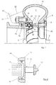
- An exhaust gas turbocharger has one arranged in the exhaust gas flow Exhaust gas turbine 1, which has a drive shaft 2 is connected to a compressor 3.
- the compressor 3 is located in an internal combustion engine 4 leading intake pipe 5 and leads the internal combustion engine pre-compressed air in this way.
- the Exhaust gas turbine 1 is located in an exhaust line 6.
- the exhaust gas turbine 1 has a spiral on the inlet side Flow channel 7, from where the exhaust gas via an annular nozzle 8 to an impeller of a turbine 9 leads, which is arranged on the drive shaft 2.
- the Flow channel 7, the ring nozzle 8 and the turbine 9 are in a common housing 10.
- Die Ring nozzle 8 is limited by axial walls.
- In the ring nozzle 8 is a guide screen 11 with a plurality of guide vanes 12.
- the guide grill 11 or the guide vanes 12 are in a known manner by means of a guide vane adjustment device 13 adjustable that the effective flow cross section of the Ring nozzle 8 between a maximum open position and an almost closed position adjustable or is
- the pressure for the adjustment of the annular piston 14 takes place via the pressure supply line 17 and the pressure accumulator 18 (or the compressed air system), with a pressure control or shut-off device 19 corresponding Pressure changes or pressure modulations carried out can be.
- the pressure control device 19 is about a control line 20 from an engine control device 21 controlled.
- the pressure can also be applied via a branch line 22 take place with the pressure connection 16 via a 3-way valve, not shown 31 is connectable in the pressure supply line 17 (shown in dashed lines in FIG. 2).
- the pressure accumulator 18 is the exhaust gas pressure in the exhaust pipe 6 charged via a check valve 23.
- the Actuation of the pressure accumulator or the pressure space 15 of the annular piston 14 can also be a motor compressor 24 take place.
- the column setting is made in conjunction with the Control device 21 and the control line 20 via the Setting the control device 19. Intermediate sizes of the gap and also the level of the contact pressure of the Annular piston 14 to the guide vanes 12 is by a Pressure modulation realized via the control device 19. If necessary, the ring piston 14 can also be used a spring 25 as a spring device, preferably is arranged in the pressure chamber 15, the ensure a neutral position or an exit gap would.
Landscapes
- Engineering & Computer Science (AREA)
- Mechanical Engineering (AREA)
- General Engineering & Computer Science (AREA)
- Supercharger (AREA)
Applications Claiming Priority (2)
| Application Number | Priority Date | Filing Date | Title |
|---|---|---|---|
| DE19961613A DE19961613A1 (de) | 1999-12-21 | 1999-12-21 | Abgasturbine eines Abgasturboladers für eine Brennkraftmaschine |
| DE19961613 | 1999-12-21 |
Publications (3)
| Publication Number | Publication Date |
|---|---|
| EP1111196A2 true EP1111196A2 (fr) | 2001-06-27 |
| EP1111196A3 EP1111196A3 (fr) | 2002-07-24 |
| EP1111196B1 EP1111196B1 (fr) | 2004-04-28 |
Family
ID=7933528
Family Applications (1)
| Application Number | Title | Priority Date | Filing Date |
|---|---|---|---|
| EP00106218A Expired - Lifetime EP1111196B1 (fr) | 1999-12-21 | 2000-03-22 | Système d'aubes de guidage variables pour la turbine d'une turbosoufflante |
Country Status (3)
| Country | Link |
|---|---|
| US (1) | US6314736B1 (fr) |
| EP (1) | EP1111196B1 (fr) |
| DE (2) | DE19961613A1 (fr) |
Cited By (6)
| Publication number | Priority date | Publication date | Assignee | Title |
|---|---|---|---|---|
| EP2037085A1 (fr) * | 2007-09-13 | 2009-03-18 | Snecma | Levier d'entraînement en rotation autour de son pivot d'aube de stator à calage variable de turbomachine |
| CN102713198A (zh) * | 2010-01-29 | 2012-10-03 | 株式会社Ihi | 涡轮增压器的密封装置 |
| ITCO20110038A1 (it) * | 2011-09-28 | 2013-03-29 | Nuovo Pignone Spa | Sistema di attuazione integrato in un compressore |
| DE102014214915B3 (de) * | 2014-07-30 | 2015-12-10 | MTU Aero Engines AG | Gehäuse für eine Gasturbine, Flugtriebwerk sowie ein Verfahren zum Betreiben einer Gasturbine |
| DE102019125823A1 (de) * | 2019-09-25 | 2021-03-25 | Mtu Friedrichshafen Gmbh | Turbinengehäuse und Abgasturbolader mit Vorleitbeschaufelung und eine Brennkraftmaschine mit einem Abgasturbolader |
| EP4361407A1 (fr) * | 2022-10-28 | 2024-05-01 | Atlas Copco Energas Gmbh | Turbomachine avec éléments de guidage réglables et procédé de fonctionnement de la turbomachine |
Families Citing this family (30)
| Publication number | Priority date | Publication date | Assignee | Title |
|---|---|---|---|---|
| DE10035762A1 (de) * | 2000-07-22 | 2002-01-31 | Daimler Chrysler Ag | Abgasturbolader für eine Brennkraftmaschine und Verfahren zum Betrieb eines Abgasturboladers |
| US6729134B2 (en) | 2001-01-16 | 2004-05-04 | Honeywell International Inc. | Variable geometry turbocharger having internal bypass exhaust gas flow |
| ITTO20010505A1 (it) * | 2001-05-25 | 2002-11-25 | Iveco Motorenforschung Ag | Turbina a geometria variabile. |
| US6665604B2 (en) | 2002-02-05 | 2003-12-16 | Honeywell International Inc. | Control method for variable geometry turbocharger and related system |
| US6681573B2 (en) | 2002-02-05 | 2004-01-27 | Honeywell International Inc | Methods and systems for variable geometry turbocharger control |
| DE10212675B4 (de) * | 2002-03-22 | 2006-05-18 | Daimlerchrysler Ag | Abgasturbolader in einer Brennkraftmaschine |
| US6996986B2 (en) | 2002-07-19 | 2006-02-14 | Honeywell International, Inc. | Control system for variable geometry turbocharger |
| US6647724B1 (en) | 2002-07-30 | 2003-11-18 | Honeywell International Inc. | Electric boost and/or generator |
| US6637205B1 (en) | 2002-07-30 | 2003-10-28 | Honeywell International Inc. | Electric assist and variable geometry turbocharger |
| EP1543220B1 (fr) * | 2002-09-05 | 2008-05-21 | Honeywell International Inc. | Turbocompresseur comprenant un dispositif de tuyere variable |
| JP2005539177A (ja) * | 2002-09-18 | 2005-12-22 | ハネウェル・インターナショナル・インコーポレーテッド | ターボチャージャのための可変ノズル装置及び同装置の作動方法 |
| WO2004027218A1 (fr) * | 2002-09-18 | 2004-04-01 | Honeywell International Inc. | Turbocompresseur possedant un dispositif de buse variable |
| DE10253693B4 (de) * | 2002-11-18 | 2005-12-01 | Borgwarner Turbo Systems Gmbh | Abgasturbolader |
| DE10311205B3 (de) * | 2003-03-14 | 2004-09-16 | Man B & W Diesel Ag | Leitapparat für eine Radialturbine |
| WO2004083606A1 (fr) * | 2003-03-21 | 2004-09-30 | Honeywell International Inc. | Concept d'ailette oscillante pour turbocompresseurs a buses a ailettes |
| WO2004099573A1 (fr) * | 2003-05-08 | 2004-11-18 | Honeywell International Inc. | Turbocompresseur a systeme d'ajutages variables |
| EP1536103B1 (fr) * | 2003-11-28 | 2013-09-04 | BorgWarner, Inc. | Turbomachine avec aubes de guidage et agencement de fixation |
| DE102004030798B4 (de) | 2004-06-25 | 2014-12-24 | Volkswagen Ag | Abgasturbolader für eine Brennkraftmaschine mit variabler Turbinengeometrie |
| JP4952558B2 (ja) * | 2007-12-12 | 2012-06-13 | 株式会社Ihi | ターボチャージャ |
| DE102008060251B4 (de) | 2008-12-03 | 2021-08-12 | BMTS Technology GmbH & Co. KG | Abgasturbolader mit variabler Turbinengeometrie |
| US8627660B2 (en) * | 2010-12-02 | 2014-01-14 | Toyota Jidosha Kabushiki Kaisha | Control device for internal combustion engine with supercharger |
| JP5710452B2 (ja) * | 2011-11-16 | 2015-04-30 | トヨタ自動車株式会社 | ターボチャージャ |
| DE102011121394A1 (de) | 2011-12-17 | 2013-06-20 | Ihi Charging Systems International Gmbh | Verstellbarer Leitapparat für eine Turbine eines Abgasturboladers, Turbine für einen Abgasturboladerund Abgasturbolader |
| DE102012001237A1 (de) * | 2012-01-18 | 2013-07-18 | Ihi Charging Systems International Gmbh | Turbine für einen Abgasturbolader |
| DE102012103412A1 (de) | 2012-04-19 | 2013-10-24 | Ihi Charging Systems International Gmbh | Turbine für einen Abgasturbolader |
| DE102013220036A1 (de) * | 2013-10-02 | 2015-04-02 | Bosch Mahle Turbo Systems Gmbh & Co. Kg | Verfahren zum Befüllen eines Druckspeichers eines Abgasturboladers |
| JP6617837B2 (ja) * | 2016-11-10 | 2019-12-11 | 株式会社Ihi | 可変ノズルユニットおよび過給機 |
| ES2959754T3 (es) * | 2016-11-18 | 2024-02-28 | Air Liquide | Boquilla de entrada de baja fricción para un turboexpansor |
| EP3929407A1 (fr) * | 2020-06-23 | 2021-12-29 | ABB Schweiz AG | Bague de tuyère modulaire pour une étage de turbine d'une turbomachine |
| CN111963470A (zh) * | 2020-08-07 | 2020-11-20 | 中国北方发动机研究所(天津) | 一种涡轮增压器压气机间隙控制装置 |
Citations (3)
| Publication number | Priority date | Publication date | Assignee | Title |
|---|---|---|---|---|
| JPH01130002A (ja) | 1987-11-12 | 1989-05-23 | Mitsubishi Heavy Ind Ltd | ラジアルタービンの可変ノズル装置 |
| DE19543190C2 (de) | 1995-11-20 | 1998-01-29 | Daimler Benz Ag | Motorbremse für eine aufgeladene Brennkraftmaschine |
| DE19838928C1 (de) | 1998-08-27 | 1999-04-22 | Daimler Chrysler Ag | Variabel einstellbares Leitschaufelgitter |
Family Cites Families (13)
| Publication number | Priority date | Publication date | Assignee | Title |
|---|---|---|---|---|
| US2341974A (en) * | 1941-05-14 | 1944-02-15 | Wright Aeronautical Corp | Supercharger control |
| US4242040A (en) * | 1979-03-21 | 1980-12-30 | Rotoflow Corporation | Thrust adjusting means for nozzle clamp ring |
| DE2931766C2 (de) * | 1979-08-04 | 1982-08-05 | MTU Motoren- und Turbinen-Union München GmbH, 8000 München | Dichtungseinrichtung für die freien Schaufelenden eines Verstell-Leitapparates einer Gasturbine |
| US4502836A (en) * | 1982-07-02 | 1985-03-05 | Swearingen Judson S | Method for nozzle clamping force control |
| JPH0610403B2 (ja) * | 1984-02-22 | 1994-02-09 | 日産自動車株式会社 | ラジアルタ−ビンの可変ノズル |
| DE3541508C1 (de) * | 1985-11-23 | 1987-02-05 | Kuehnle Kopp Kausch Ag | Abgasturbolader |
| DE3941715A1 (de) * | 1989-12-18 | 1991-06-20 | Porsche Ag | Abgasturbolader fuer eine brennkraftmaschine |
| US5214920A (en) * | 1990-11-27 | 1993-06-01 | Leavesley Malcolm G | Turbocharger apparatus |
| SE501488C2 (sv) * | 1993-07-08 | 1995-02-27 | Mecel Ab | Arrangemang och förfarande för tomgångsreglering och laddtryckreglering i en överladdad förbränningsmotor |
| US5564895A (en) * | 1995-04-26 | 1996-10-15 | Rotoflow Corporation | Active automatic clamping control |
| DE19615237C2 (de) * | 1996-04-18 | 1999-10-28 | Daimler Chrysler Ag | Abgasturbolader für eine Brennkraftmaschine |
| JPH10130002A (ja) | 1996-10-28 | 1998-05-19 | Unitika Ltd | 三次元網目状金属酸化物およびその製造方法 |
| DE19651498C1 (de) * | 1996-12-11 | 1998-04-16 | Daimler Benz Ag | Abgasturboladerturbine für eine Brennkraftmaschine |
-
1999
- 1999-12-21 DE DE19961613A patent/DE19961613A1/de not_active Ceased
-
2000
- 2000-03-22 EP EP00106218A patent/EP1111196B1/fr not_active Expired - Lifetime
- 2000-03-22 DE DE50006238T patent/DE50006238D1/de not_active Expired - Fee Related
- 2000-04-26 US US09/558,834 patent/US6314736B1/en not_active Expired - Lifetime
Patent Citations (3)
| Publication number | Priority date | Publication date | Assignee | Title |
|---|---|---|---|---|
| JPH01130002A (ja) | 1987-11-12 | 1989-05-23 | Mitsubishi Heavy Ind Ltd | ラジアルタービンの可変ノズル装置 |
| DE19543190C2 (de) | 1995-11-20 | 1998-01-29 | Daimler Benz Ag | Motorbremse für eine aufgeladene Brennkraftmaschine |
| DE19838928C1 (de) | 1998-08-27 | 1999-04-22 | Daimler Chrysler Ag | Variabel einstellbares Leitschaufelgitter |
Cited By (14)
| Publication number | Priority date | Publication date | Assignee | Title |
|---|---|---|---|---|
| EP2037085A1 (fr) * | 2007-09-13 | 2009-03-18 | Snecma | Levier d'entraînement en rotation autour de son pivot d'aube de stator à calage variable de turbomachine |
| FR2921100A1 (fr) * | 2007-09-13 | 2009-03-20 | Snecma Sa | Levier d'entrainement en rotation autour de son pivot d'aube de stator a calage variable de turbomachine |
| US8197190B2 (en) | 2007-09-13 | 2012-06-12 | Snecma | Lever for rotating a turbomachine variable-pitch stator vane about its pivot |
| CN102713198B (zh) * | 2010-01-29 | 2014-08-20 | 株式会社Ihi | 涡轮增压器的密封装置 |
| CN102713198A (zh) * | 2010-01-29 | 2012-10-03 | 株式会社Ihi | 涡轮增压器的密封装置 |
| ITCO20110038A1 (it) * | 2011-09-28 | 2013-03-29 | Nuovo Pignone Spa | Sistema di attuazione integrato in un compressore |
| WO2013045514A1 (fr) * | 2011-09-28 | 2013-04-04 | Nuovo Pignone S.P.A. | Appareil du type actuateur et procédé pour l'intégration dudit actuateur dans une turbomachine |
| JP2014528044A (ja) * | 2011-09-28 | 2014-10-23 | ヌオーヴォ ピニォーネ ソシエタ ペル アチオニ | 圧縮機統合作動システム |
| DE102014214915B3 (de) * | 2014-07-30 | 2015-12-10 | MTU Aero Engines AG | Gehäuse für eine Gasturbine, Flugtriebwerk sowie ein Verfahren zum Betreiben einer Gasturbine |
| US9988927B2 (en) | 2014-07-30 | 2018-06-05 | MTU Aero Engines AG | Housing for a gas turbine, aircraft engine, and a process for operating a gas turbine |
| DE102019125823A1 (de) * | 2019-09-25 | 2021-03-25 | Mtu Friedrichshafen Gmbh | Turbinengehäuse und Abgasturbolader mit Vorleitbeschaufelung und eine Brennkraftmaschine mit einem Abgasturbolader |
| EP3798419A1 (fr) * | 2019-09-25 | 2021-03-31 | MTU Friedrichshafen GmbH | Carter de turbine de turbocompresseur pourvu d'aubage redresseur à geométrie fixe |
| DE102019125823B4 (de) | 2019-09-25 | 2023-05-11 | Rolls-Royce Solutions GmbH | Turbinengehäuse und Abgasturbolader mit Vorleitbeschaufelung und eine Brennkraftmaschine mit einem Abgasturbolader |
| EP4361407A1 (fr) * | 2022-10-28 | 2024-05-01 | Atlas Copco Energas Gmbh | Turbomachine avec éléments de guidage réglables et procédé de fonctionnement de la turbomachine |
Also Published As
| Publication number | Publication date |
|---|---|
| US6314736B1 (en) | 2001-11-13 |
| EP1111196B1 (fr) | 2004-04-28 |
| DE19961613A1 (de) | 2001-07-19 |
| DE50006238D1 (de) | 2004-06-03 |
| EP1111196A3 (fr) | 2002-07-24 |
Similar Documents
| Publication | Publication Date | Title |
|---|---|---|
| EP1111196B1 (fr) | Système d'aubes de guidage variables pour la turbine d'une turbosoufflante | |
| EP1071871B1 (fr) | Turbine de turbosoufflante a gaz d'echappement | |
| EP0093462B1 (fr) | Turbocompresseur avec une valve annulaire glissante | |
| DE19727141C1 (de) | Brennkraftmaschinen - Turbolader - System | |
| DE2925268C2 (fr) | ||
| EP1488084B1 (fr) | Turbocompresseur a gaz d'echappement a geometrie variable | |
| EP2025896B1 (fr) | Compresseur radial pour turbocompresseur | |
| DE69702132T2 (de) | Steuersystem für ein stufenloses getriebe | |
| DE69328453T2 (de) | Aufladevorrichtung für einen Verbrennungsmotor | |
| EP0991856B1 (fr) | Systeme turbocompresseur pour moteurs a combustion interne | |
| DE19836677C2 (de) | Motorbremseinrichtung für eine Brennkraftmaschine mit einem Abgasturbolader | |
| EP3650677B1 (fr) | Procédé de fonctionnement d'un système de moteur à combustion interne | |
| DE3320699C2 (de) | Vorrichtung zum Verändern des Leitschaufelwinkels bei axialen Strömungsmaschinen | |
| DE19511232A1 (de) | Verfahren und Vorrichtung zur Registeraufladung einer Brennkraftmaschine | |
| DE102018113050B4 (de) | Wastegate-anordnung, ein turbolader zur verwendung der wastegate-anordnung und ein verfahren zum verbinden von teilen einer wastegate-anordnung | |
| EP2547911A1 (fr) | Ensemble palier pour arbre de rotor de turbine | |
| DE4316900C2 (de) | Drehzahlvariator | |
| EP2788591A1 (fr) | Turbine destinée à un turbocompresseur à gaz d'échappement | |
| EP3056690B1 (fr) | Compresseur centrifuge, turbocompresseur et procédé correspondant de fonctionnement d'un compresseur centrifuge | |
| EP1259737A1 (fr) | Dispositif de regulation pour pompes volumetriques | |
| DE102007017844B4 (de) | Abgasturbolader, Brennkraftmaschine mit diesem Abgasturbolader und Verfahren zum Regeln des Ladedrucks des Abgasturboladers | |
| DE102008052321B4 (de) | Turbolader mit Magnetlageranordnung | |
| DE1952728B2 (de) | Bypass-ventileinrichtung fuer die nutzleistungsturbine einer gasturbinenanlage | |
| DE102005062682A1 (de) | Verdichter im Ansaugtrakt einer Brennkraftmaschine und Abgasturbolader für eine Brennkraftmaschine | |
| DE4325600C2 (de) | Aufgeladene Brennkraftmaschine mit mindestens zwei Abgasturboladern |
Legal Events
| Date | Code | Title | Description |
|---|---|---|---|
| PUAI | Public reference made under article 153(3) epc to a published international application that has entered the european phase |
Free format text: ORIGINAL CODE: 0009012 |
|
| AK | Designated contracting states |
Kind code of ref document: A2 Designated state(s): AT BE CH CY DE DK ES FI FR GB GR IE IT LI LU MC NL PT SE |
|
| AX | Request for extension of the european patent |
Free format text: AL;LT;LV;MK;RO;SI |
|
| PUAL | Search report despatched |
Free format text: ORIGINAL CODE: 0009013 |
|
| AK | Designated contracting states |
Kind code of ref document: A3 Designated state(s): AT BE CH CY DE DK ES FI FR GB GR IE IT LI LU MC NL PT SE |
|
| AX | Request for extension of the european patent |
Free format text: AL;LT;LV;MK;RO;SI |
|
| 17P | Request for examination filed |
Effective date: 20021214 |
|
| AKX | Designation fees paid |
Designated state(s): DE FR GB IT |
|
| GRAP | Despatch of communication of intention to grant a patent |
Free format text: ORIGINAL CODE: EPIDOSNIGR1 |
|
| GRAS | Grant fee paid |
Free format text: ORIGINAL CODE: EPIDOSNIGR3 |
|
| GRAA | (expected) grant |
Free format text: ORIGINAL CODE: 0009210 |
|
| AK | Designated contracting states |
Kind code of ref document: B1 Designated state(s): DE FR GB IT |
|
| REG | Reference to a national code |
Ref country code: GB Ref legal event code: FG4D Free format text: NOT ENGLISH |
|
| REG | Reference to a national code |
Ref country code: IE Ref legal event code: FG4D Free format text: GERMAN |
|
| REF | Corresponds to: |
Ref document number: 50006238 Country of ref document: DE Date of ref document: 20040603 Kind code of ref document: P |
|
| GBT | Gb: translation of ep patent filed (gb section 77(6)(a)/1977) |
Effective date: 20040705 |
|
| REG | Reference to a national code |
Ref country code: IE Ref legal event code: FD4D |
|
| ET | Fr: translation filed | ||
| PLBE | No opposition filed within time limit |
Free format text: ORIGINAL CODE: 0009261 |
|
| STAA | Information on the status of an ep patent application or granted ep patent |
Free format text: STATUS: NO OPPOSITION FILED WITHIN TIME LIMIT |
|
| PGFP | Annual fee paid to national office [announced via postgrant information from national office to epo] |
Ref country code: FR Payment date: 20050311 Year of fee payment: 6 |
|
| PGFP | Annual fee paid to national office [announced via postgrant information from national office to epo] |
Ref country code: GB Payment date: 20050314 Year of fee payment: 6 |
|
| 26N | No opposition filed |
Effective date: 20050131 |
|
| PG25 | Lapsed in a contracting state [announced via postgrant information from national office to epo] |
Ref country code: GB Free format text: LAPSE BECAUSE OF NON-PAYMENT OF DUE FEES Effective date: 20060322 |
|
| GBPC | Gb: european patent ceased through non-payment of renewal fee |
Effective date: 20060322 |
|
| REG | Reference to a national code |
Ref country code: FR Ref legal event code: ST Effective date: 20061130 |
|
| PG25 | Lapsed in a contracting state [announced via postgrant information from national office to epo] |
Ref country code: FR Free format text: LAPSE BECAUSE OF NON-PAYMENT OF DUE FEES Effective date: 20060331 |
|
| PGFP | Annual fee paid to national office [announced via postgrant information from national office to epo] |
Ref country code: IT Payment date: 20100329 Year of fee payment: 11 |
|
| REG | Reference to a national code |
Ref country code: DE Ref legal event code: R119 Ref document number: 50006238 Country of ref document: DE Ref country code: DE Ref legal event code: R409 Ref document number: 50006238 Country of ref document: DE |
|
| REG | Reference to a national code |
Ref country code: DE Ref legal event code: R409 Ref document number: 50006238 Country of ref document: DE |
|
| PG25 | Lapsed in a contracting state [announced via postgrant information from national office to epo] |
Ref country code: DE Free format text: LAPSE BECAUSE OF NON-PAYMENT OF DUE FEES Effective date: 20111001 |
|
| REG | Reference to a national code |
Ref country code: DE Ref legal event code: R085 Ref document number: 50006238 Country of ref document: DE Effective date: 20111210 |
|
| PG25 | Lapsed in a contracting state [announced via postgrant information from national office to epo] |
Ref country code: IT Free format text: LAPSE BECAUSE OF NON-PAYMENT OF DUE FEES Effective date: 20110322 |
|
| PGRI | Patent reinstated in contracting state [announced from national office to epo] |
Ref country code: DE Effective date: 20120119 |
|
| REG | Reference to a national code |
Ref country code: DE Ref legal event code: R081 Ref document number: 50006238 Country of ref document: DE Owner name: BURANI CONSULTING LIMITED LIABILITY COMPANY, W, US Free format text: FORMER OWNER: DAIMLER AG, 70327 STUTTGART, DE Effective date: 20120418 |
|
| PGFP | Annual fee paid to national office [announced via postgrant information from national office to epo] |
Ref country code: DE Payment date: 20190215 Year of fee payment: 20 |
|
| REG | Reference to a national code |
Ref country code: DE Ref legal event code: R071 Ref document number: 50006238 Country of ref document: DE |