EP1111232B1 - Dispositif d'injection - Google Patents
Dispositif d'injection Download PDFInfo
- Publication number
- EP1111232B1 EP1111232B1 EP00128437A EP00128437A EP1111232B1 EP 1111232 B1 EP1111232 B1 EP 1111232B1 EP 00128437 A EP00128437 A EP 00128437A EP 00128437 A EP00128437 A EP 00128437A EP 1111232 B1 EP1111232 B1 EP 1111232B1
- Authority
- EP
- European Patent Office
- Prior art keywords
- pressure
- piezoelectric element
- housing
- pressure line
- line
- Prior art date
- Legal status (The legal status is an assumption and is not a legal conclusion. Google has not performed a legal analysis and makes no representation as to the accuracy of the status listed.)
- Expired - Lifetime
Links
- 238000002347 injection Methods 0.000 title claims description 15
- 239000007924 injection Substances 0.000 title claims description 15
- 230000001105 regulatory effect Effects 0.000 claims description 5
- 238000000034 method Methods 0.000 claims description 3
- 238000007789 sealing Methods 0.000 claims description 3
- 238000010276 construction Methods 0.000 claims 1
- 230000002093 peripheral effect Effects 0.000 claims 1
- 239000012530 fluid Substances 0.000 description 14
- 239000000446 fuel Substances 0.000 description 13
- 230000000694 effects Effects 0.000 description 5
- 238000011156 evaluation Methods 0.000 description 5
- 239000000463 material Substances 0.000 description 4
- 238000002485 combustion reaction Methods 0.000 description 3
- 229910000831 Steel Inorganic materials 0.000 description 2
- 238000009530 blood pressure measurement Methods 0.000 description 2
- 230000006835 compression Effects 0.000 description 2
- 238000007906 compression Methods 0.000 description 2
- 239000010959 steel Substances 0.000 description 2
- 230000004323 axial length Effects 0.000 description 1
- 229910010293 ceramic material Inorganic materials 0.000 description 1
- 230000003247 decreasing effect Effects 0.000 description 1
- 230000001419 dependent effect Effects 0.000 description 1
- 239000002283 diesel fuel Substances 0.000 description 1
- 239000002828 fuel tank Substances 0.000 description 1
- 238000005259 measurement Methods 0.000 description 1
- 238000010992 reflux Methods 0.000 description 1
- 239000000243 solution Substances 0.000 description 1
- 239000013589 supplement Substances 0.000 description 1
- 230000002277 temperature effect Effects 0.000 description 1
- 230000002123 temporal effect Effects 0.000 description 1
Images
Classifications
-
- F—MECHANICAL ENGINEERING; LIGHTING; HEATING; WEAPONS; BLASTING
- F02—COMBUSTION ENGINES; HOT-GAS OR COMBUSTION-PRODUCT ENGINE PLANTS
- F02M—SUPPLYING COMBUSTION ENGINES IN GENERAL WITH COMBUSTIBLE MIXTURES OR CONSTITUENTS THEREOF
- F02M65/00—Testing fuel-injection apparatus, e.g. testing injection timing ; Cleaning of fuel-injection apparatus
- F02M65/003—Measuring variation of fuel pressure in high pressure line
-
- F—MECHANICAL ENGINEERING; LIGHTING; HEATING; WEAPONS; BLASTING
- F02—COMBUSTION ENGINES; HOT-GAS OR COMBUSTION-PRODUCT ENGINE PLANTS
- F02D—CONTROLLING COMBUSTION ENGINES
- F02D41/00—Electrical control of supply of combustible mixture or its constituents
- F02D41/24—Electrical control of supply of combustible mixture or its constituents characterised by the use of digital means
- F02D41/26—Electrical control of supply of combustible mixture or its constituents characterised by the use of digital means using computer, e.g. microprocessor
- F02D41/28—Interface circuits
-
- F—MECHANICAL ENGINEERING; LIGHTING; HEATING; WEAPONS; BLASTING
- F02—COMBUSTION ENGINES; HOT-GAS OR COMBUSTION-PRODUCT ENGINE PLANTS
- F02M—SUPPLYING COMBUSTION ENGINES IN GENERAL WITH COMBUSTIBLE MIXTURES OR CONSTITUENTS THEREOF
- F02M63/00—Other fuel-injection apparatus having pertinent characteristics not provided for in groups F02M39/00 - F02M57/00 or F02M67/00; Details, component parts, or accessories of fuel-injection apparatus, not provided for in, or of interest apart from, the apparatus of groups F02M39/00 - F02M61/00 or F02M67/00; Combination of fuel pump with other devices, e.g. lubricating oil pump
- F02M63/0012—Valves
- F02M63/0014—Valves characterised by the valve actuating means
- F02M63/0015—Valves characterised by the valve actuating means electrical, e.g. using solenoid
- F02M63/0026—Valves characterised by the valve actuating means electrical, e.g. using solenoid using piezoelectric or magnetostrictive actuators
-
- F—MECHANICAL ENGINEERING; LIGHTING; HEATING; WEAPONS; BLASTING
- F02—COMBUSTION ENGINES; HOT-GAS OR COMBUSTION-PRODUCT ENGINE PLANTS
- F02M—SUPPLYING COMBUSTION ENGINES IN GENERAL WITH COMBUSTIBLE MIXTURES OR CONSTITUENTS THEREOF
- F02M63/00—Other fuel-injection apparatus having pertinent characteristics not provided for in groups F02M39/00 - F02M57/00 or F02M67/00; Details, component parts, or accessories of fuel-injection apparatus, not provided for in, or of interest apart from, the apparatus of groups F02M39/00 - F02M61/00 or F02M67/00; Combination of fuel pump with other devices, e.g. lubricating oil pump
- F02M63/0012—Valves
- F02M63/0031—Valves characterized by the type of valves, e.g. special valve member details, valve seat details, valve housing details
- F02M63/004—Sliding valves, e.g. spool valves, i.e. whereby the closing member has a sliding movement along a seat for opening and closing
-
- F—MECHANICAL ENGINEERING; LIGHTING; HEATING; WEAPONS; BLASTING
- F02—COMBUSTION ENGINES; HOT-GAS OR COMBUSTION-PRODUCT ENGINE PLANTS
- F02M—SUPPLYING COMBUSTION ENGINES IN GENERAL WITH COMBUSTIBLE MIXTURES OR CONSTITUENTS THEREOF
- F02M63/00—Other fuel-injection apparatus having pertinent characteristics not provided for in groups F02M39/00 - F02M57/00 or F02M67/00; Details, component parts, or accessories of fuel-injection apparatus, not provided for in, or of interest apart from, the apparatus of groups F02M39/00 - F02M61/00 or F02M67/00; Combination of fuel pump with other devices, e.g. lubricating oil pump
- F02M63/02—Fuel-injection apparatus having several injectors fed by a common pumping element, or having several pumping elements feeding a common injector; Fuel-injection apparatus having provisions for cutting-out pumps, pumping elements, or injectors; Fuel-injection apparatus having provisions for variably interconnecting pumping elements and injectors alternatively
- F02M63/0225—Fuel-injection apparatus having a common rail feeding several injectors ; Means for varying pressure in common rails; Pumps feeding common rails
-
- F—MECHANICAL ENGINEERING; LIGHTING; HEATING; WEAPONS; BLASTING
- F02—COMBUSTION ENGINES; HOT-GAS OR COMBUSTION-PRODUCT ENGINE PLANTS
- F02M—SUPPLYING COMBUSTION ENGINES IN GENERAL WITH COMBUSTIBLE MIXTURES OR CONSTITUENTS THEREOF
- F02M63/00—Other fuel-injection apparatus having pertinent characteristics not provided for in groups F02M39/00 - F02M57/00 or F02M67/00; Details, component parts, or accessories of fuel-injection apparatus, not provided for in, or of interest apart from, the apparatus of groups F02M39/00 - F02M61/00 or F02M67/00; Combination of fuel pump with other devices, e.g. lubricating oil pump
- F02M63/02—Fuel-injection apparatus having several injectors fed by a common pumping element, or having several pumping elements feeding a common injector; Fuel-injection apparatus having provisions for cutting-out pumps, pumping elements, or injectors; Fuel-injection apparatus having provisions for variably interconnecting pumping elements and injectors alternatively
- F02M63/0225—Fuel-injection apparatus having a common rail feeding several injectors ; Means for varying pressure in common rails; Pumps feeding common rails
- F02M63/023—Means for varying pressure in common rails
- F02M63/0235—Means for varying pressure in common rails by bleeding fuel pressure
- F02M63/025—Means for varying pressure in common rails by bleeding fuel pressure from the common rail
-
- F—MECHANICAL ENGINEERING; LIGHTING; HEATING; WEAPONS; BLASTING
- F02—COMBUSTION ENGINES; HOT-GAS OR COMBUSTION-PRODUCT ENGINE PLANTS
- F02D—CONTROLLING COMBUSTION ENGINES
- F02D41/00—Electrical control of supply of combustible mixture or its constituents
- F02D41/30—Controlling fuel injection
- F02D41/38—Controlling fuel injection of the high pressure type
- F02D2041/389—Controlling fuel injection of the high pressure type for injecting directly into the cylinder
-
- F—MECHANICAL ENGINEERING; LIGHTING; HEATING; WEAPONS; BLASTING
- F02—COMBUSTION ENGINES; HOT-GAS OR COMBUSTION-PRODUCT ENGINE PLANTS
- F02D—CONTROLLING COMBUSTION ENGINES
- F02D2250/00—Engine control related to specific problems or objectives
- F02D2250/31—Control of the fuel pressure
-
- F—MECHANICAL ENGINEERING; LIGHTING; HEATING; WEAPONS; BLASTING
- F02—COMBUSTION ENGINES; HOT-GAS OR COMBUSTION-PRODUCT ENGINE PLANTS
- F02D—CONTROLLING COMBUSTION ENGINES
- F02D41/00—Electrical control of supply of combustible mixture or its constituents
- F02D41/30—Controlling fuel injection
- F02D41/38—Controlling fuel injection of the high pressure type
- F02D41/3809—Common rail control systems
-
- F—MECHANICAL ENGINEERING; LIGHTING; HEATING; WEAPONS; BLASTING
- F02—COMBUSTION ENGINES; HOT-GAS OR COMBUSTION-PRODUCT ENGINE PLANTS
- F02M—SUPPLYING COMBUSTION ENGINES IN GENERAL WITH COMBUSTIBLE MIXTURES OR CONSTITUENTS THEREOF
- F02M2200/00—Details of fuel-injection apparatus, not otherwise provided for
- F02M2200/24—Fuel-injection apparatus with sensors
Definitions
- the invention relates to a device for measuring and / or control the pressure in a pressure line according to the preamble of the claim 1 and an injection device, in particular for common rail injection in diesel engines, with a pressure line and at least a device for measuring and / or regulating the pressure in the Pressure line.
- a device with the characteristics of the generic term of the Claim 1 is known from DE 1 808 506 U.
- injectors used in conjunction with internal combustion engines used is at least one to the pressure line Injection nozzle connected to the combustion chamber of a associated cylinder at the right time a certain amount of fuel is supplied.
- the fuel quantity injected under high pressure directly into the cylinder.
- each cylinder is associated with an injection nozzle, wherein the Injectors connected to a common fuel pressure line are, in which the fuel is pumped by a pump.
- a Such arrangement is called “Common Rail Injector” or “Common Rail Injection ".
- the pressure measurement and / or pressure control takes place taking advantage of the piezoelectric effect.
- the piezoelectric Element interacts at its end facing the housing opening with the pressurized fluid in the pressure line, so that the piezoelectric element between the housing, on which the piezoelectric element is supported with its one end, and the fluid in the pressure line, with which it interacts at its opposite end, depending on the prevailing fluid pressure more or less is compressed.
- the piezoelectric element through the Applied pressure generated electrical voltage, which is a measure of the pressure in the pressure line prevailing pressure can tapped and a control / evaluation are supplied to this way to measure the fluid pressure.
- An advantage of the invention is the speed of the piezoelectric Element. So it is possible according to the invention, between two successive injection events occurring pressure fluctuations not only to recognize, but also with a high temporal Measure resolution.
- Another advantage of the invention is that even very high Pressures can be measured with which e.g. in pressure pipes of working for common rail injection serving injectors becomes.
- the piezoelectric element comprises a sensor area for measuring the pressure prevailing in the pressure line and an actuator area for changing the pressure in the pressure line. While the pressure can be measured with the sensor area, is with the actuator area of the pressure changeable.
- the dimensions, the sensor area and the actuator area in the direction of the piezo effect can basically be chosen arbitrarily. Is preferred the sensor area only so large that it sufficient for further processing provides large voltage signals, e.g. in the range of a few volts lie.
- the actuator range is chosen as large as possible to maximum To achieve dimensional changes.
- a method for pressure control which is also the subject of Invention is not only applied to the piezoelectric element Pressure measured in the pressure line, but also a Voltage for changing the dimensions of the piezoelectric element depending on the measured pressure to the piezoelectric Element created.
- the piezoelectric element serves simultaneously as a sensor and as Actuator, i. as an element with which the pressure in the pressure line both measured and changed.
- the invention allows therefore an extremely fast pressure regulation, by the tension, which corresponds to the pressure applied to the piezoelectric element, monitored and in case of a deviation of the measured pressure from a setpoint by applying a corresponding voltage to the piezoelectric element a change in length of the piezoelectric element and thus a pressure change in the pressure line is generated. In this way, in particular between successive injection events occurring pressure fluctuations in the pressure line be corrected.
- the piezoelectric element acts at its pressure line facing End together with a separate pressure body.
- a separate pressure body has the advantage that this can be easily adapted to the dimensions of the housing and basically shaped in any manner, e.g. in addition to serve as a valve element.
- the pressure body arranged without force in the housing is. This ensures that no disturbing to the pressure body Forces, but only the piezoelectric element and the fluid in act on the pressure line.
- Such an arrangement of the pressure hull has the advantage that the over the pressure hull on the piezoelectric Element applied forces solely by the pressure in the Pressure line determined and in particular from the position of the pressure hull are independent in the housing.
- the pressure body as a sealing the inner wall of the housing adjacent the piston element is formed.
- the preferably circular free inner cross-sectional area of the housing thus determines the size of the with the pressure fluid in the pressure line cooperating end face of the pressure hull and thus at a Pressure change applied to the piezoelectric element force.
- the pressure body a recess, in particular in the form of a circumferential recess on, at least in certain positions of the pressure hull over a Inlet channel connected to the pressure line and a drain channel connected to a return line.
- the pressure body as a valve element and the inventive Measuring / control device thus additionally as a pressure relief valve be used, via the fluid from the pressure line in the Return line can drain.
- the recess of the pressure hull over a compensation channel is connected to a portion of the housing, the located on the side facing away from the pressure line side of the pressure hull is.
- the compensation channel also with the return line connected and in particular formed in sections of the flow channel be.
- the compensation channel ensures that any leakage from Pressurized fluid from the recess in the housing with regard to Pressure measurement and / or pressure control are not critical.
- the piezoelectric element is coupled to a thermal compensator, which is designed such that by means of the piezoelectric Elementes generated pressure changes at least substantially independent of temperature and in particular independent of thermal dimensional changes of the housing are.
- the invention also relates to a method for pressure regulation in one Pressure line with at least one such device, which in Claim 20 has specified steps.
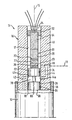
- FIGS Drawing whose only figure is a sectioned side view a partially illustrated injection device according to one embodiment of the invention.
- a pressure line 12 also referred to as "rail”, to which at least one, in multi-cylinder internal combustion engines more, injectors are connected, which are not shown in the figure.
- About the pressure line 12 is the below as a fluid or Druckfluid designated fuel, especially diesel fuel, or supplied to the injectors.
- At the pressure line 12 is at least one not shown pump connected to the in the pressure line 12th a fuel pressure sufficient to meet the respective requirements is.
- a tubular steel housing 16 is screwed, which has a circular free inner cross-sectional area.
- the housing 16 is at one end with an external thread 56th provided with a thread, not shown in an opening of the Wall of the pressure line 12 cooperates.
- a carrier 52 for screwed one explained in more detail below arrangement, wherein the Housing 16 is closed fluid-tight by the carrier 52.
- the one of the Housing 16 and the carrier 52 limited space thus provides an extension the pressure line 12, wherein the housing 16 with the pressure line 12 communicates via the housing opening 18, the on in the pressure line 12 protruding end of the housing 16 is formed.
- a rod-shaped thermal compensator 54 Securely connected to the carrier 52 is a rod-shaped thermal compensator 54, which is discussed in detail elsewhere and at of which the housing opening 18 and thus the pressure line 12 facing End of a piezoelectric element 22 is attached.
- the piezoelectric element 22 acts with a designed as a piston element pressure body 34 together, the one upper section 62 and a lower section 64.
- a piston element pressure body 34 About one Connecting portion 66 with respect to the two sections 62, 64th reduced diameter are the two cylindrical or plate-shaped Sections 62, 64 connected together and in a constant held axial distance from each other.
- the pressure body 34 consequently has a recess 38 in the form of a circumferential recess.
- the two sections 62, 64 of the pressure body 64 are each sealingly on the inner wall 36 of the housing 16, so that the of the recess 38 formed chamber opposite the pressure line 12 on the one hand and the region 17 of the housing 16 between the upper portion 62nd the pressure body 34 and the carrier 52 on the other hand is sealed.
- the pressure body 34 is suitable Means, e.g. by an inwardly projecting shoulder in the area of Housing opening 18 secured against falling out of the housing.
- the piezoelectric element 22 is made of a plurality of plate-shaped Single elements 23 constructed, stacked one above the other and with vertical to dashed longitudinal axis 15 of the housing 16 extending Flat sides are arranged. Some of the individual elements 23 are in the figure by perpendicular to the housing longitudinal axis 15 extending lines indicated by way of example.
- the individual elements 23 may in a practical embodiment of the piezoelectric Element 22 each having a thickness of 80 to 100 microns and e.g. be made of a piezoelectric ceramic material.
- the axial length of the superimposed individual elements 23 constructed piezoelectric element 22 is in a practical Execution for example about 50 mm.
- the piezoelectric element 22 is in a sensor area 26 and an actuator area 28, wherein the sensor area 26 has a smaller number of individual elements 23 than the actuator area 28 and closer to the housing opening 18 is located.
- the border 27 between the sensor area 26 and the actuator area 28 is in the figure indicated by a dashed line.
- the sensor area 26 and the actuator portion 28 could also be reversed in the axial direction be arranged so that the actuator portion 28 closer to the housing opening 18 would be.
- the functions of the sensor area 26 on the one hand and the actuator area 28 on the other hand assigned individual elements 23 differ in that the entirety of the sensor region 26 forming Single elements 23 as a passive part of the piezoelectric element 22nd for measuring and the entirety of the actuator area 28 forming Single elements 23 as an active part of the piezoelectric element 22nd is used to change the fluid pressure in the pressure line 12.
- the sensor region 26 with not shown electrical connection areas provided with which the voltage applied to the sensor area 26 exerted pressure from the sensor area 26 forming Single elements 23 is generated in total, can be tapped. This voltage is across two of the four leads shown in the figure 24 of a control / evaluation device, not shown fed.
- the individual elements 23 of the piezoelectric element 22 are such executed and are selected or driven so that the piezoelectric Effect in a direction perpendicular to the flat sides of the plate-shaped individual elements 23 and thus in the direction of the housing longitudinal axis 15 is exploited.
- the tapped at the sensor region 26 voltage is the sum of the individual elements 23 generated by the applied pressure individual voltages, while the total induced change in length of the actuator area 28, the sum of the individual thickness changes the individual elements 23 is.
- the size of each effect can thus by the assignment of the corresponding number of individual elements 23 targeted to the sensor area 26 and the actuator 28 are, i. at a given total length of the piezoelectric Element 22 can change its behavior by dividing the total existing individual elements 23 on the two areas 26, 28 determined become.
- the piezoelectric elements are single 23 made of a material in which an applied operating voltage from about 100 to 200 V, a dimensional or thickness change of at least the order of magnitude has about 1 per thousand result.
- piezoelectric elements can also be used according to the invention which differ from the embodiment described above Have structure.
- an inlet channel 42 is formed, the pressure line 12 with the between the upper portion 62nd and the lower portion 64 of the pressure hull 34 located chamber 38 connects.
- the inlet channel 42 thus represents a bypass line, with which the lower portion 64 of the pressure body 34 is bypassed.
- a drainage channel 44 is formed in the housing wall 48, the chamber 38 connects to a return line 13, which is in operation leads to a fuel tank of the vehicle, not shown, in which the injection device is used.
- the flow cross-section of the inlet channel 42 and the flow channel 44 is much smaller than that of the housing 16 and thus, the cooperating with the fluid in the pressure line 12 surface 58 of the pressure hull 34th
- the drainage channel 44 also forms part of a compensation channel 46, in the between the support 52 and the upper portion 62 of Pressure body 34 located portion 17 of the housing 16 opens and thus a bypass line for bypassing the upper portion 62 of the Represents pressure body 34.
- the axial movements of the pressure body 34, the fluid and the can be caused piezoelectric element 22 are in one Practical embodiment of the invention comparable to the diameter the opening 42a of the inlet channel 42. Notwithstanding the illustration in the figure, the pressure body 34 is preferably in operation during operation axial position, in which the openings 42a, 44a at each time from the upper portion 62 or the lower portion 64 of Pressure hull 34 are partially covered. The axial position of the pressure hull 34 can be adjusted by changing the screwing depth of the carrier 52 become.
- a piezoelectric element with a Valve element cooperate, e.g. by a coil spring biased in the direction of a valve seat.
- the valve element that with the piezoelectric element e.g. over a push rod or a plunger cooperates in an operating position through the piezoelectric element against the restoring force of the coil spring from Valve seat lifted.
- the valve element is thus characterized by pressure fluctuations in the pressure line or by changes in length of the piezoelectric Element in both directions axially movable, and indeed either with support by or against the spring force.
- the fluid pressure in the pressure line can be monitored and regulated in this way become.
- due to the lifted off the valve seat valve element a flow connection past the valve element, whereby a pressure relief possibility is given.
- a pressure change within the pressure line 12 is over the Pressure body 34 on the sensor portion 26 of the piezoelectric element 22 transmitted and in the form of a measure of the current pressure representing voltage across the leads 24 to the not shown Control / evaluation device transmitted.
- a pressure change in the pressure line 12, which is a predetermined amount can be counteracted by means of the tax / Evaluation device, at which the pressure change is determined, a corresponding Voltage is applied to the actuator region 28, the one Elongation or compression of the actuator 28 and a corresponding axial movement of the pressure body 34 results, by the an increase or decrease prevailing in the pressure line 12 Pressure is effected.
- the voltage applied to the actuator area 28 is increased or decreased until the control / evaluation from the sensor area 23 - with the same time in the pressure line 12 prevailing pressure is measured - a given Pressure corresponding voltage signal is received.
- Unwanted pressure fluctuations in the pressure line 12 can this way due to the rapidity with which the piezoelectric element 22 reacts to pressure and voltage changes within the shortest possible time Time to be corrected.
- the pressure in the pressure line 12 is determined by the ratio between the per unit time by means of the pump in the pressure line 12 funded fuel supply and the fuel drain via the injection nozzles (consumption) and via the pressure body 34 (Return).
- the fuel discharge via the pressure body 34 is dependent from the axial position of the inlet opening 42a of the inlet channel 42 more or less covering pressure body 34.
- About the actuator area 28 of the piezoelectric element 22 can consequently the fuel outflow and thus the pressure in the pressure line 12 can be adjusted.
- the compensator 54 is particularly in terms of its dimensions and material depending on the thermal expansion behavior of the housing 16 and the piezoelectric Element 22 executed such that axial dimensional changes of the housing 16 and the piezoelectric element 22 compensated become.
- the relative position between the pressure line 12 and the piezoelectric Element 22 - and thus the axial position of the pressure hull 34 - is thus independent of temperature fluctuations, so that Temperature-induced dimensional changes of the housing 16 not too Pressure changes in the pressure line 12 lead.
- the measuring / control device 14 can thus with the measuring / control device 14 more Functions are fulfilled.
- the pressure line 12 prevailing pressure can be determined.
- the pressure by regulating the amount of reflux very quickly to the desired Value to be set.
- the pressure body 34 is used together with the inlet channel 42 and the drainage channel 44 as an extraordinary fast pressure relief valve.
Landscapes
- Engineering & Computer Science (AREA)
- Chemical & Material Sciences (AREA)
- Combustion & Propulsion (AREA)
- Mechanical Engineering (AREA)
- General Engineering & Computer Science (AREA)
- Computer Hardware Design (AREA)
- Microelectronics & Electronic Packaging (AREA)
- Fuel-Injection Apparatus (AREA)
Claims (20)
- Dispositif destiné à la mesure et/ou à la régulation de la pression dans une conduite sous pression (12) avec un boítier (16) qui peut être raccordé à la conduite sous pression (12) et qui, à l'état raccordé, communique avec la conduite sous pression (12) par l'intermédiaire d'un orifice de boítier (18), et avec un élément piézoélectrique (22) disposé dans le boítier (16), qui est dirigé vers l'orifice de boítier (18) avec l'une de ses extrémités et qui s'appuie sur le boítier (16) avec son extrémité opposée,
caractérisé en ce que l'élément piézoélectrique (22) comporte une zone de détecteur (26) pour mesurer la pression régnant dans la conduite sous pression (12) et une zone d'actionneur (28) pour faire varier la pression dans la conduite sous pression (12). - Dispositif selon la revendication 1,
caractérisé en ce que l'élément piézoélectrique (22) est muni de raccords (24) par l'intermédiaire desquels les tensions électriques induites par la pression peuvent être prélevées pour la mesure de la pression et/ou les tensions électriques peuvent être appliquées pour générer des variations dimensionnelles. - Dispositif selon la revendication 1 ou 2,
caractérisé en ce que la zone de détecteur (26) et la zone d'actionneur (28) sont disposées l'un derrière l'autre dans la direction des variations dimensionnelles de l'élément piézoélectrique (22). - Dispositif selon au moins l'une quelconque des revendications précédentes, caractérisé en ce que la zone d'actionneur (28) présente une dilatation plus grande que la zone de détecteur (26) dans la direction des variations dimensionnelles de l'élément piézoélectrique (22).
- Dispositif selon au moins l'une quelconque des revendications précédentes, caractérisé en ce que l'élément piézoélectrique (22) est constitué d'une pluralité d'éléments individuels en forme de plaques (23), une zone de détecteur (26) et une zone d'actionneur (28) de l'élément piézoélectrique (22) comprenant, de préférence, chacune une pile d'éléments individuels (23).
- Dispositif selon au moins l'une quelconque des revendications précédentes, caractérisé en ce que l'élément piézoélectrique (22) coopère avec un corps sous pression séparé (34), à son extrémité dirigée vers la conduit sous pression (12).
- Dispositif selon la revendication 6, caractérisé en ce que le corps sous pression (34) est disposé dans le boítier (16) sans être soumis à l'action des forces.
- Dispositif selon la revendication 6 ou 7, caractérisé en ce que le corps sous pression (34) est configuré comme un élément de piston s'appuyant de manière étanche sur la paroi intérieure (36) du boítier (16).
- Dispositif selon au moins l'une quelconque des revendications 6 à 8, caractérisé en ce que le corps sous pression (34) comporte un évidement (38), en particulier sous forme d'un creux circonférentiel qui, au moins dans certaines positions du corps sous pression (34), communique avec la conduite sous pression (12) par l'intermédiaire d'un canal d'arrivée (42) et qui est raccordé à une conduite de retour (13) par l'intermédiaire d'un canal de décharge (44), moyennant quoi la section de passage du canal d'arrivée (42) et du canal de décharge (44) est, de préférence, respectivement plus petite, en particulier sensiblement plus petite, que celle de la surface active (58) du corps sous pression (34) dirigée vers la conduite sous pression (12).
- Dispositif selon au moins l'une quelconque des revendications 6 à 9, caractérisé en ce qu'un évidement (38) du corps sous pression (34) communique avec une zone (17) du boítier (16) par l'intermédiaire d'un canal de compensation (46), laquelle zone est placée du côté du corps sous pression (34) dirigé à l'opposé de la conduite sous pression (12).
- Dispositif selon la revendication 10, caractérisé en ce que le canal de compensation (46) communique avec une conduite de retour (13) et en ce qu'il est formé par un canal de décharge (44), de préférence au moins par segments.
- Dispositif selon au moins l'une quelconque des revendications 8 à 11, caractérisé en ce qu'un canal d'arrivée (42), un canal de décharge (44) et/ou un canal de compensation (46) sont formés dans la paroi du boítier (48).
- Dispositif selon au moins l'une quelconque des revendications 8 à 12, caractérisé en ce que le canal d'arrivée (42) et le canal de décharge (44) présentent au moins approximativement la même résistance à l'écoulement.
- Dispositif selon au moins l'une quelconque des revendications 8 à 13, caractérisé en ce que le canal d'arrivée (42) et le canal de décharge (44) débouchent au moins approximativement à la même hauteur dans l'évidement (38) du corps sous pression (34).
- Dispositif selon au moins l'une quelconque des revendications précédentes, caractérisé en ce que le boítier (16) a une forme tubulaire.
- Dispositif selon au moins l'une quelconque des revendications précédentes, caractérisé en ce que le boítier (16) est vissé dans la conduite sous pression (12).
- Dispositif selon au moins l'une quelconque des revendications précédentes, caractérisé en ce que l'élément piézoélectrique (22) est vissé dans le boítier (16), l'élément piézoélectrique (22) étant, de préférence, monté dans un support (52) séparé, raccordé au boítier (16) et, de préférence, obturant le boítier (16) de manière étanche aux fluides.
- Dispositif selon au moins l'une quelconque des revendications précédentes, caractérisé en ce que l'élément piézoélectrique (22) est couplé à un compensateur thermique (54) qui est configuré de telle manière que les pressions mesurées et/ou les variations de pression générées à l'aide de l'élément piézoélectrique (22) sont au moins sensiblement indépendantes de la température et, en particulier, indépendantes des variations dimensionnelles thermiques du boítier (16).
- Dispositif d'injection, en particulier pour l'injection Common Rail dans les moteurs Diesel, avec une conduite sous pression (12) et au moins un dispositif (14) selon au moins l'une quelconque des revendications 1 à 18.
- Procédé pour la régulation de pression dans une conduite sous pression (12) avec au moins un dispositif (14) selon au moins l'une quelconque des revendications 1 à 18, dans lequel la pression appliquée à l'élément piézoélectrique (22) est mesurée dans la conduite sous pression (12) et une tension est appliquée à l'élément piézoélectrique (22) pour faire varier les dimensions de l'élément piézoélectrique (22) en fonction de la pression mesurée.
Applications Claiming Priority (2)
| Application Number | Priority Date | Filing Date | Title |
|---|---|---|---|
| DE19963134 | 1999-12-24 | ||
| DE19963134A DE19963134A1 (de) | 1999-12-24 | 1999-12-24 | Einspritzvorrichtung |
Publications (3)
| Publication Number | Publication Date |
|---|---|
| EP1111232A2 EP1111232A2 (fr) | 2001-06-27 |
| EP1111232A3 EP1111232A3 (fr) | 2003-08-27 |
| EP1111232B1 true EP1111232B1 (fr) | 2005-03-09 |
Family
ID=7934592
Family Applications (1)
| Application Number | Title | Priority Date | Filing Date |
|---|---|---|---|
| EP00128437A Expired - Lifetime EP1111232B1 (fr) | 1999-12-24 | 2000-12-22 | Dispositif d'injection |
Country Status (2)
| Country | Link |
|---|---|
| EP (1) | EP1111232B1 (fr) |
| DE (2) | DE19963134A1 (fr) |
Families Citing this family (3)
| Publication number | Priority date | Publication date | Assignee | Title |
|---|---|---|---|---|
| DE102004022371A1 (de) | 2004-05-06 | 2005-12-01 | Bayerische Motoren Werke Ag | Verfahren zum Steuern eines Kraftstoffeinspritzventils |
| US8805607B2 (en) | 2007-09-20 | 2014-08-12 | Robert Bosch Gmbh | Vapour measurement |
| DE102016225400B4 (de) * | 2016-12-19 | 2022-12-29 | Robert Bosch Gmbh | Dämpfungssystem in einem Hochdruck-Kraftstoffeinspritzsystem |
Family Cites Families (5)
| Publication number | Priority date | Publication date | Assignee | Title |
|---|---|---|---|---|
| DE1808506U (de) * | 1960-01-30 | 1960-03-24 | Walther Beck | Elektronisches dieselpruefgeraet. |
| DE1808506A1 (de) * | 1968-11-13 | 1970-06-11 | Kabel Metallwerke Ghh | Wand- oder Deckenverkleidung |
| AT304102B (de) * | 1970-10-07 | 1972-12-27 | List Hans | Einrichtung zur Messung des Druckes in Einspritzleitungen |
| DE3037078C2 (de) * | 1980-10-01 | 1982-08-12 | Daimler-Benz Ag, 7000 Stuttgart | Elektrisch angesteuertes Stellglied |
| DE19753072C2 (de) * | 1997-11-29 | 1999-11-18 | Bosch Gmbh Robert | Kraftstoffversorgungssystem für eine Brennkraftmaschine insbesondere eines Kraftfahrzeugs |
-
1999
- 1999-12-24 DE DE19963134A patent/DE19963134A1/de not_active Withdrawn
-
2000
- 2000-12-22 EP EP00128437A patent/EP1111232B1/fr not_active Expired - Lifetime
- 2000-12-22 DE DE50009718T patent/DE50009718D1/de not_active Expired - Lifetime
Also Published As
| Publication number | Publication date |
|---|---|
| EP1111232A3 (fr) | 2003-08-27 |
| EP1111232A2 (fr) | 2001-06-27 |
| DE19963134A1 (de) | 2001-06-28 |
| DE50009718D1 (de) | 2005-04-14 |
Similar Documents
| Publication | Publication Date | Title |
|---|---|---|
| DE69911670T2 (de) | Kraftstoffeinspritzventil | |
| EP0323984A1 (fr) | Installation d'injection de carburant pour moteurs a combustion interne | |
| EP1567765B1 (fr) | Soupape d'injection | |
| EP1135594B1 (fr) | Soupape pour commander le passage de fluides | |
| DE10135735B4 (de) | Verfahren zum Betreiben einer Brennkraftmaschine, insbesondere mit Direkteinspritzung, sowie Computerprogramm und Steuer- und/oder Regelgerät | |
| EP1505295A1 (fr) | Methode de positionner d'un actionneur d'un injecteur de carburant et dispositif pour effecteur de la methode | |
| EP2387661B1 (fr) | Injecteur de carburant pour moteurs à combustion interne | |
| EP2206912A2 (fr) | Injecteur de carburant | |
| EP1117922B1 (fr) | Injecteur a rampe commune | |
| DE10019765A1 (de) | Ventil zum Steuern von Flüssigkeiten | |
| DE10139871B4 (de) | Ventil zum Steuern von Flüssigkeiten | |
| WO2008025597A1 (fr) | Dispositif d'injection de carburant pour un moteur à combustion interne à plusieurs cylindres | |
| DE4437927C2 (de) | Magnetventilgesteuerte Kraftstoffeinspritzvorrichtung mit einer Einspritzdüse zur Kraftstoffeinspritzung in den Brennraum einer Dieselbrennkraftmaschine | |
| WO2001081752A2 (fr) | Vanne de commande de liquides | |
| DE19946830A1 (de) | Ventil zum Steuern von Flüssigkeiten | |
| DE19936667A1 (de) | Common-Rail-Injektor | |
| WO2001081755A1 (fr) | Soupape de regulation de fluides | |
| WO2002092996A1 (fr) | Soupape de commande de liquides | |
| EP1111232A2 (fr) | Dispositif d'injection | |
| WO2008145330A1 (fr) | Injecteur haute pression pour moteurs à combustion interne à appui de tige de commande à charge de flambage croissante par l'intermédiaire de carburant haute pression | |
| WO2002061265A1 (fr) | Soupape de commande de liquides | |
| EP1048843B1 (fr) | Dispositif d'injection de combustible | |
| EP1664525B1 (fr) | Dispositif de dosage | |
| EP1307646A1 (fr) | Ensemble soupape, en particulier pour un systeme d'injection de carburant d'un moteur a combustion interne | |
| WO2008122521A1 (fr) | Soupape et système d'injection pour un moteur à combustion interne comprenant une soupape |
Legal Events
| Date | Code | Title | Description |
|---|---|---|---|
| PUAI | Public reference made under article 153(3) epc to a published international application that has entered the european phase |
Free format text: ORIGINAL CODE: 0009012 |
|
| AK | Designated contracting states |
Kind code of ref document: A2 Designated state(s): AT BE CH CY DE DK ES FI FR GB GR IE IT LI LU MC NL PT SE TR |
|
| AX | Request for extension of the european patent |
Free format text: AL;LT;LV;MK;RO;SI |
|
| PUAL | Search report despatched |
Free format text: ORIGINAL CODE: 0009013 |
|
| AK | Designated contracting states |
Designated state(s): AT BE CH CY DE DK ES FI FR GB GR IE IT LI LU MC NL PT SE TR |
|
| AX | Request for extension of the european patent |
Extension state: AL LT LV MK RO SI |
|
| RIC1 | Information provided on ipc code assigned before grant |
Ipc: 7F 02M 65/00 B Ipc: 7G 01L 23/10 B Ipc: 7F 02M 59/46 B Ipc: 7G 01L 9/00 B Ipc: 7F 02M 63/02 A |
|
| 17P | Request for examination filed |
Effective date: 20030926 |
|
| 17Q | First examination report despatched |
Effective date: 20031104 |
|
| AKX | Designation fees paid |
Designated state(s): DE ES FR GB IT |
|
| GRAP | Despatch of communication of intention to grant a patent |
Free format text: ORIGINAL CODE: EPIDOSNIGR1 |
|
| GRAS | Grant fee paid |
Free format text: ORIGINAL CODE: EPIDOSNIGR3 |
|
| GRAA | (expected) grant |
Free format text: ORIGINAL CODE: 0009210 |
|
| AK | Designated contracting states |
Kind code of ref document: B1 Designated state(s): DE ES FR GB IT |
|
| PG25 | Lapsed in a contracting state [announced via postgrant information from national office to epo] |
Ref country code: IT Free format text: LAPSE BECAUSE OF FAILURE TO SUBMIT A TRANSLATION OF THE DESCRIPTION OR TO PAY THE FEE WITHIN THE PRESCRIBED TIME-LIMIT;WARNING: LAPSES OF ITALIAN PATENTS WITH EFFECTIVE DATE BEFORE 2007 MAY HAVE OCCURRED AT ANY TIME BEFORE 2007. THE CORRECT EFFECTIVE DATE MAY BE DIFFERENT FROM THE ONE RECORDED. Effective date: 20050309 Ref country code: GB Free format text: LAPSE BECAUSE OF FAILURE TO SUBMIT A TRANSLATION OF THE DESCRIPTION OR TO PAY THE FEE WITHIN THE PRESCRIBED TIME-LIMIT Effective date: 20050309 |
|
| REG | Reference to a national code |
Ref country code: GB Ref legal event code: FG4D Free format text: NOT ENGLISH |
|
| REG | Reference to a national code |
Ref country code: IE Ref legal event code: FG4D Free format text: GERMAN |
|
| REF | Corresponds to: |
Ref document number: 50009718 Country of ref document: DE Date of ref document: 20050414 Kind code of ref document: P |
|
| PG25 | Lapsed in a contracting state [announced via postgrant information from national office to epo] |
Ref country code: ES Free format text: LAPSE BECAUSE OF FAILURE TO SUBMIT A TRANSLATION OF THE DESCRIPTION OR TO PAY THE FEE WITHIN THE PRESCRIBED TIME-LIMIT Effective date: 20050620 |
|
| GBV | Gb: ep patent (uk) treated as always having been void in accordance with gb section 77(7)/1977 [no translation filed] |
Effective date: 20050309 |
|
| PLBE | No opposition filed within time limit |
Free format text: ORIGINAL CODE: 0009261 |
|
| STAA | Information on the status of an ep patent application or granted ep patent |
Free format text: STATUS: NO OPPOSITION FILED WITHIN TIME LIMIT |
|
| ET | Fr: translation filed | ||
| 26N | No opposition filed |
Effective date: 20051212 |
|
| REG | Reference to a national code |
Ref country code: FR Ref legal event code: TP |
|
| PGFP | Annual fee paid to national office [announced via postgrant information from national office to epo] |
Ref country code: FR Payment date: 20130110 Year of fee payment: 13 |
|
| PGFP | Annual fee paid to national office [announced via postgrant information from national office to epo] |
Ref country code: DE Payment date: 20121231 Year of fee payment: 13 |
|
| REG | Reference to a national code |
Ref country code: DE Ref legal event code: R119 Ref document number: 50009718 Country of ref document: DE |
|
| REG | Reference to a national code |
Ref country code: DE Ref legal event code: R082 Ref document number: 50009718 Country of ref document: DE Representative=s name: MANITZ, FINSTERWALD & PARTNER GBR, DE |
|
| REG | Reference to a national code |
Ref country code: DE Ref legal event code: R082 Ref document number: 50009718 Country of ref document: DE Representative=s name: MANITZ, FINSTERWALD & PARTNER GBR, DE Effective date: 20140702 Ref country code: DE Ref legal event code: R081 Ref document number: 50009718 Country of ref document: DE Owner name: DELPHI INTERNATIONAL OPERATIONS LUXEMBOURG S.A, LU Free format text: FORMER OWNER: DELPHI TECHNOLOGIES HOLDING S.A.R.L., BASCHARAGE, LU Effective date: 20140702 |
|
| REG | Reference to a national code |
Ref country code: FR Ref legal event code: ST Effective date: 20140829 |
|
| REG | Reference to a national code |
Ref country code: DE Ref legal event code: R119 Ref document number: 50009718 Country of ref document: DE Effective date: 20140701 |
|
| PG25 | Lapsed in a contracting state [announced via postgrant information from national office to epo] |
Ref country code: DE Free format text: LAPSE BECAUSE OF NON-PAYMENT OF DUE FEES Effective date: 20140701 |
|
| PG25 | Lapsed in a contracting state [announced via postgrant information from national office to epo] |
Ref country code: FR Free format text: LAPSE BECAUSE OF NON-PAYMENT OF DUE FEES Effective date: 20131231 |