EP1664525B1 - Dispositif de dosage - Google Patents
Dispositif de dosage Download PDFInfo
- Publication number
- EP1664525B1 EP1664525B1 EP04787126A EP04787126A EP1664525B1 EP 1664525 B1 EP1664525 B1 EP 1664525B1 EP 04787126 A EP04787126 A EP 04787126A EP 04787126 A EP04787126 A EP 04787126A EP 1664525 B1 EP1664525 B1 EP 1664525B1
- Authority
- EP
- European Patent Office
- Prior art keywords
- end cap
- metering device
- housing
- actuator
- accordance
- Prior art date
- Legal status (The legal status is an assumption and is not a legal conclusion. Google has not performed a legal analysis and makes no representation as to the accuracy of the status listed.)
- Expired - Lifetime
Links
- 238000007789 sealing Methods 0.000 claims description 33
- 239000012530 fluid Substances 0.000 claims description 18
- 210000005069 ears Anatomy 0.000 claims description 12
- 239000012528 membrane Substances 0.000 claims description 12
- 230000008859 change Effects 0.000 claims description 10
- 238000004519 manufacturing process Methods 0.000 claims description 7
- 238000003860 storage Methods 0.000 claims description 7
- 238000000034 method Methods 0.000 claims description 6
- 239000000463 material Substances 0.000 description 7
- 230000000694 effects Effects 0.000 description 6
- 239000000446 fuel Substances 0.000 description 4
- 230000008901 benefit Effects 0.000 description 2
- 239000000919 ceramic Substances 0.000 description 2
- 230000007423 decrease Effects 0.000 description 2
- 238000009434 installation Methods 0.000 description 2
- 230000008569 process Effects 0.000 description 2
- 101100328887 Caenorhabditis elegans col-34 gene Proteins 0.000 description 1
- 206010067171 Regurgitation Diseases 0.000 description 1
- 230000004913 activation Effects 0.000 description 1
- 230000003679 aging effect Effects 0.000 description 1
- 230000002457 bidirectional effect Effects 0.000 description 1
- 230000005540 biological transmission Effects 0.000 description 1
- 238000010276 construction Methods 0.000 description 1
- 230000008602 contraction Effects 0.000 description 1
- 238000007796 conventional method Methods 0.000 description 1
- 238000001816 cooling Methods 0.000 description 1
- 238000006073 displacement reaction Methods 0.000 description 1
- 238000005516 engineering process Methods 0.000 description 1
- 230000006870 function Effects 0.000 description 1
- 230000010354 integration Effects 0.000 description 1
- 230000007257 malfunction Effects 0.000 description 1
- 239000002184 metal Substances 0.000 description 1
- 230000004048 modification Effects 0.000 description 1
- 238000012986 modification Methods 0.000 description 1
- 230000010287 polarization Effects 0.000 description 1
- 230000009467 reduction Effects 0.000 description 1
- 229920002545 silicone oil Polymers 0.000 description 1
- 239000007787 solid Substances 0.000 description 1
- 210000002023 somite Anatomy 0.000 description 1
- 125000006850 spacer group Chemical group 0.000 description 1
- 230000035882 stress Effects 0.000 description 1
- 230000003746 surface roughness Effects 0.000 description 1
- 230000002277 temperature effect Effects 0.000 description 1
- 230000001052 transient effect Effects 0.000 description 1
- 238000003466 welding Methods 0.000 description 1
Images


Classifications
-
- F—MECHANICAL ENGINEERING; LIGHTING; HEATING; WEAPONS; BLASTING
- F02—COMBUSTION ENGINES; HOT-GAS OR COMBUSTION-PRODUCT ENGINE PLANTS
- F02M—SUPPLYING COMBUSTION ENGINES IN GENERAL WITH COMBUSTIBLE MIXTURES OR CONSTITUENTS THEREOF
- F02M61/00—Fuel-injectors not provided for in groups F02M39/00 - F02M57/00 or F02M67/00
- F02M61/16—Details not provided for in, or of interest apart from, the apparatus of groups F02M61/02 - F02M61/14
- F02M61/167—Means for compensating clearance or thermal expansion
-
- F—MECHANICAL ENGINEERING; LIGHTING; HEATING; WEAPONS; BLASTING
- F02—COMBUSTION ENGINES; HOT-GAS OR COMBUSTION-PRODUCT ENGINE PLANTS
- F02M—SUPPLYING COMBUSTION ENGINES IN GENERAL WITH COMBUSTIBLE MIXTURES OR CONSTITUENTS THEREOF
- F02M51/00—Fuel-injection apparatus characterised by being operated electrically
- F02M51/06—Injectors peculiar thereto with means directly operating the valve needle
- F02M51/0603—Injectors peculiar thereto with means directly operating the valve needle using piezoelectric or magnetostrictive operating means
-
- F—MECHANICAL ENGINEERING; LIGHTING; HEATING; WEAPONS; BLASTING
- F02—COMBUSTION ENGINES; HOT-GAS OR COMBUSTION-PRODUCT ENGINE PLANTS
- F02M—SUPPLYING COMBUSTION ENGINES IN GENERAL WITH COMBUSTIBLE MIXTURES OR CONSTITUENTS THEREOF
- F02M61/00—Fuel-injectors not provided for in groups F02M39/00 - F02M57/00 or F02M67/00
- F02M61/16—Details not provided for in, or of interest apart from, the apparatus of groups F02M61/02 - F02M61/14
- F02M61/168—Assembling; Disassembling; Manufacturing; Adjusting
Definitions
- the invention relates to a metering device, in particular with an actuator unit as a drive for a valve in a common-rail diesel injector.
- piezoelectric actuator Mechanical tolerances, temperature-related and pressure-related changes in length, aging effects of a particular used in a fluid valve PMA ( P iezoelektrischer M ultilayer A ktor), hereinafter referred to as "piezoelectric actuator", have an immediate effect on the opening stroke of a connected to the piezoelectric fluid valve and thus on its Dosiermenge.
- PMA P iezoelektrischer M ultilayer A ktor
- the achievable by the inverse piezoelectric effect in high-performance ceramics elongation ratio of the piezoelectric actuator due to the application of a maximum permissible for continuous operation field strength of about 2KV / mm is only 1.2-1.4 parts per thousand (ie 1.2-1.4 microns elongation each 1 mm length of the piezo actuator).
- the inverse piezoelectric effect leads to an elongation of a maximum of 56 ⁇ m.
- the coefficient of thermal expansion strongly depends on the polarization state and the mechanical and electrical history of the piezoelectric actuator.
- the temperature dependence of the length of the piezoelectric actuator is non-linear.
- the coefficient of thermal expansion for the same piezo actuator can be in the range of -5 * 10 -6 1 / K to + 7 * 10 -6 1 / K, as disclosed in the lecture by DR. Lubitz at the 2002 Actuator Fair in Bremen.
- the generated by the electrical charging of the piezoelectric actuator positive change in length of the piezoelectric actuator is used in current common-rail diesel injectors for regurgitation of a sealing element.
- a "thermal gap”, ie a safety distance, is provided between the freely movable end of a piezoelectric actuator unit (PAU), which is designed as a plunger or to which a plunger is mechanically rigidly coupled and to the sealing element of typically 3-5 ⁇ m.
- the PAU consists of an upper end cap which is mechanically rigidly mounted and which contains at least one bore through which the electrical connections of the piezoelectric actuator can be led to the outside, a lower end cap which is designed as a plunger or to which a plunger is mechanically rigidly coupled, the piezoactuator and a tubular spring in which the piezoelectric actuator is welded under a compressive bias of about 600N-800N between the two end caps.
- a thermal coordination between the actuator housing and the PAU can not be ideal.
- the safety distance serves to open the sealing element in the event of a greater thermal expansion of the PAU relative to the actuator housing, resulting in permanent leakage through the servo valve.
- the stated fluctuations make the PMA temperature coefficient clear that even such a distance is not always sufficient.
- the units of the injector are at high temperature. Due to the associated thermal expansion of the piezoelectric actuator relative to the not perfectly tunable housing, the thermal distance can be overcome and open the sealing element despite missing Piezoan horrung, especially in the parking condition caused by the fluid pressure counterforce F 0 no longer acts on the sealing element. The sealing element is thus still open when the engine is switched off.
- the fluid pressure which presses on the sealing element from the other direction, but can then reach in the activated state of the injector up to 2000 bar and cause forces or opposing forces up to 600 N.
- these forces ensure a defined closing of the sealing element, despite an overstretching of the actuator.
- An internal high-pressure pump in the motor vehicle is in a renewed attempt to start the engine and thus the injector but no longer able, if the injector is still hot to build up the required pressure to close the sealing element, so that it leads to malfunction of the injector.
- JP 61008462 discloses a metering device having a housing, an actuator guided in the housing, a hydraulic compensation element and an end cap at one end of the actuator.
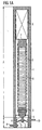
- An actuator unit A customary in the prior art is disclosed in US Pat FIG. 1 shown. It consists of a housing 1, a piezoelectric actuator 2 with a tube spring 8, a first and a second end cap 3.7, wherein the first end cap 3 is provided with a plunger 4.
- the piezoelectric actuator 2 is welded under a pressure bias of about 600 to 800 N in the tube spring 8 to avoid harmful tensile stresses during operation.
- the second end cap 7 is supported against the housing 1, while the first end cap 3 when driven together with the Plunger 4 presses against the sealing element 6 of the seat valve 12.
- the sealing element realized as a ball 6 (not shown) by means of a weak return spring held in the seat 12 with about 5N.
- the normal state no activation of the piezoelectric actuator
- thermal changes are not short-term processes in the range of less than 10 ms, but are rather in the second to minute range.
- a slow expansion of the actuator 2 can, however, by a hydraulic compensation element X, as in FIG. 1a shown to be intercepted.
- Such a hydraulic compensation element X is preferably located between the end cap 7 of the actuator 2 and the upper end of the housing 1 and is secured to the housing. Using such a hydraulic compensation element so the thermal expansion of the actuator now takes place in the direction of the end cap 7 and does not necessarily lead to a change in the distance between the sealing element 6 and the plunger 4 and thus not to permanent leaks.
- the hydraulic compensation element X has a stiffness comparable to a solid body compared to short-term application of force, wherein, despite this rigidity, the hydraulic compensation element or a component of the hydraulic compensation element which is indirectly or directly connected to the piezoactuator gives way to a negligible path.
- these negligible paths add up when the piezo actuator is actuated several times, so that the hydraulic compensation element or the component of the hydraulic compensation element is displaced upwards by the maximum deflection of the piezoactuator, thereby increasing the distance between the plunger 4 and the sealing element 6 such that the plunger no longer reaches the sealing element when the piezoactuator is actuated again. An opening of the sealing element 6 is no longer possible in this case.
- the invention has for its object to provide a device and / or a method by which / always a predeterminable distance between a sealing element and an actuator unit can be maintained.
- This metering device has the advantage that the smallest possible distance between the sealing element and the actuator is maintained even with fluctuating working temperatures. Thus, an opening of the sealing element is always ensured by the actuator, which by the hydraulic Compensation element achievable compensation of the thermal expansion of the actuator is maintained.
- the first end cap is guided past the stop and the end cap and the stop face each other in such a way that upon movement of the end cap in the direction of the hydraulic compensating element, the end cap hits the stop and this movement is blocked ,
- the method corresponds to a simple key-lock relationship between the end cap and the stop. It is particularly suitable and safe for easy production of the metering device.
- the key-lock ratio is preferably a bayonet lock.
- the actuator is preferably a piezoelectric actuator.
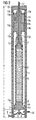
- FIG. 2 shows a metering device with the known features FIG. 1 , an already mentioned hydraulic compensation element 13, modified end caps 7 ', 3' and a stop 14.
- the installation of the hydraulic compensation element 13 in the metering device can be done in a simple manner between one end of the housing 1 and the piezoelectric actuator 2, which advantageously simplifies the integration in or the modification of existing injectors.
- the hydraulic compensation element is preferably fixedly attached to the inner wall of the housing 1.
- the hydraulic compensation element 13 is fundamentally rigid with respect to a brief application of force and at the same time yields with a thermally induced change in length of the actuator.
- the hydraulic compensation element 13 preferably has at least one hydraulic chamber 13c, a hollow-cylindrical housing 13a and a piston 13b, the piston 13b or the housing 13a being connected to the second end cap 7 'of the actuator 2.
- the hydraulic chamber 13c is located between respective axially pressure-effective surfaces of the piston and the housing and between at least two clearance fits 13g, which are formed between the piston and the housing.
- the axially effective surfaces are aligned substantially axially.
- the term "axial” is understood to mean the direction of the force actions and transmissions of the piezoactuator or of the hydraulic compensation element. However, “axial” is also understood to mean “essentially axial”.
- the game fits 13g basically have a strong fluid throttling effect.
- the hydraulic compensation element can be filled under pressure with a fluid, preferably silicone oil. It is preferred that the hydraulic compensation element has an axial through hole 13d through the leads 17 can be performed to the piezoelectric actuator 2. In particular, the piston 13b is provided with this through hole 13d.
- the piston 13b and the housing 13a are displaceable relative to each other at a slow thermally induced change in length of the actuator relative to each other, so that the hydraulic compensation element yields in this time.
- the piston In the case of a momentary application of force, however, the piston only shifts by a negligible distance relative to the housing, so that the hydraulic compensation element is considered to be rigid.
- the hydraulic compensation element for increased rigidity comprises a plurality, in particular two, hydraulic chambers.
- the housing 13a is extended by a part to form another, similar to the first hydraulic chamber 13c hydraulic chamber between the piston 13b and the housing 13a as mentioned above.
- the hydraulic compensation element would be bidirectional in this case.
- the hydraulic compensation element 13 is provided at its two end faces with membranes 13f, which are preferably fastened respectively to the piston 13b and to the housing 13a.
- Storage volumes 13e are formed between the housing, the diaphragms and the piston through the diaphragm.
- the membranes can also bulge at elevated temperature, so that they can compensate for a thermal change in volume of the fluid located in the hydraulic compensation element. They preferably each have temperature expansion coefficients which differ from those of the housing and / or the piston.
- the membranes are preferably designed as annular flat membranes.
- the hydraulic compensation element hydraulically via a bore in the housing 13 a hydraulic compensation element with a balance memory is connected to an increasing volume change of the fluid in the hydraulic compensation element at elevated temperature even better than only with the aforementioned membranes 13f and storage volumes 13e to be able to intercept.
- the balance memory preferably has a membrane, which can be realized as an elastic sleeve, and a storage volume enclosed underneath.
- the elastic sleeve of the compensating accumulator is preferably arranged on the lateral surface of the housing 13a. At elevated temperature of the fluid, the membrane expands so that the fluid in the hydraulic compensation element, a larger volume is available and thus no disturbing net force effect between the piston and the housing comes about.
- the housing 13 a of the hydraulic compensation element In order to provide sufficient space for the expansion of the elastic sleeve of the reservoir between the housing 13 a of the hydraulic compensation element and the inner wall of the housing 1 of the metering device, it is preferred that the housing 13 a of the hydraulic compensation element by means of a spacer with the inner wall of the housing 1 of the metering device mechanically connected.
- the balance memory can also be realized in the form of an external hydraulic accumulator.
- the piston 13b or housing 13a be provided with axial bores which connect the storage volumes 13e to the hydraulic chambers 13c to facilitate return of the fluid during the blanking interval of the piezoactuator into the hydraulic chambers and into the storage volumes.
- the openings of the bores are provided with check valves, so-called flapper valves, so that the openings of the bores close when the piezoelectric actuator is deflected for a short time and thus the hydraulic compensation element is still stiff in the case of short-term application of force.
- the check valves open due to a pressure reduction in the hydraulic chambers 13c.
- the housing 1 of the metering device is as needed after the original structure FIG. 1 extended to accommodate the hydraulic compensation element 13 can.
- the second end cap 7 ' is welded to the piston 13b of the hydraulic compensation element.
- the housing 1 is closed at the top by a closing element 15, preferably a fixed bearing.
- the piezoelectric actuator unit PAU referred to hereinafter as actuator unit A, mentioned in the introduction to the description, comprises the arrangement of features which are directly or indirectly mechanically connected directly to the piezoactuator 2, except for the latter FIG. 1 known features still a first, lower and modified end cap 3 ', which is equipped with a valve unit B directed to a ram 4.
- valve unit B at least one arrangement which comprises the valve seat 12 and the sealing element 6 is understood.
- the valve unit may also have feed and return 9, 10 for the fuel.
- the end cap 3 ' is preferably frusto-conical, whose lateral surface has steps.
- the end cap 3 'but at least two ears 3'a have their substantially axially, in the opposite direction to the sealing element 6 aligned surfaces upon retraction of the actuator on the likewise axially aligned surfaces 14a of the stopper 14 abut.
- a diaphragm 5 seals the piezoactuator 2 against a fuel in the metering device, which flows from the inlet 9 through the seat valve 12 to the return 10 when the sealing element 6 is opened.
- the membrane 5 preferably connects the housing 1 with the end cap 3 '.
- the piezoelectric actuator 2 is preferably also provided with a second, upper end cap 7 ', which is connected to the hydraulic compensation element. It is preferred that the end cap 7 'has an axial bore 16 for connecting wires 17, in order to simplify the contacting of the piezoelectric actuator 2 to a control electronics (not shown).
- An essential element of the metering device is the stop 14, which counteracts a change in the equilibrium position of the piston 13b of the hydraulic compensation element, and thus also the position of the end cap 3 ', acts.
- the stop 14 can be considered as a taper of the inner diameter of the housing 1.
- inner diameter or “diameter” is always understood to mean a transverse-axial diameter which runs at right angles to the longitudinal axis of the actuator.
- the stopper is preferably broken by two recesses. The stop allows the expansion of the actuator in the direction of the sealing element 6, but prevents retraction of the end cap 3 'over a predefined distance from the sealing element 6 addition.
- the stop 14 can be formed in a variety of variants.
- Essential in a concrete embodiment is its mounting below the piezoelectric actuator to allow the stretching of the actuator upwards or in the opposite direction to the sealing element.
- FIG. 3 shows the lower end cap 3 'as a truncated cone shape with a lateral surface which is provided with steps.
- the end cap has two ears 3'a, on the transverse axial plane of which there is an outer diameter of the end cap which is greater than the minimum inner diameter of the stop or the taper 14 of the housing 1.
- the ears 3'a of the end cap 3 ' are guided past the recesses 14a of the stop 14. Subsequently, the end cap is rotated so that the ears 3'a can no longer be pushed past the stop by pulling back the end cap.
- FIG. 4 shows how the end cap 3 'before the finished state of the metering device is the stopper 14 opposite.
- the cross-sectional view on the left shows how the outer diameter of the end cap 3 'at the level of the ears 3'a is greater than the minimum inner diameter of the stop.
- the recesses of the stop are shown at 14a.
- the recess 14a and stop are arranged in each case to each other. The position of the ears 3'a of the end cap in this view is such that the end cap 3 'can be guided past the stop without rotation by the ears 3'a being passable through the recesses 14a.
- the end cap 3 ' is thus basically the right counterpart to the stop 14, so that thereby forms a key lock arrangement.
- the stop and the end cap thus form a bayonet lock.
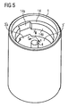
- FIG. 5 shows a further three-dimensional view of the lower portion of the metering device before its finished manufactured state. As in FIG. 4 shown, the ears are 3'a the recesses 14a opposite, so that the end cap 3 'can be moved past the stop 14.
- a stop 14 Another possibility for forming a stop 14 is the direct connection between the plunger 4 and the sealing element 6 of the seat valve 12, so that the plunger also takes over the role of the sealing element.
- the valve seat itself becomes a stop element, since the sealing element or the plunger has a diameter such that it or it can not be guided past the valve seat.
- the stop 14 can also be replaced by an additional spring between the piston 13b and the fixed bearing 15.
- the bias of the spring in the manufacture of the metering device ensures an effective downward force acting on the plunger 4 to the sealing element 6 of the valve unit B and counteracts a change in the equilibrium position of the piston.
- the piston thus always experiences a restoring force in order to prevent a displacement of the equilibrium position of the piston and to ensure a defined contact between the plunger and the sealing element.
- the elasticity of the membrane 5 is suitable as a restoring element for a desired equilibrium position. Welding the membrane 5 to the end cap 3 'and the housing 1 ensures protection against rotation of the end cap in a position in which the recesses 14a and the ears 3'a are opposite in the finished state of the metering device, and the End cap is accidentally pulled past the stop again.
- the metering device according to the invention is used in a common-rail diesel injector.
Landscapes
- Engineering & Computer Science (AREA)
- Chemical & Material Sciences (AREA)
- Combustion & Propulsion (AREA)
- Mechanical Engineering (AREA)
- General Engineering & Computer Science (AREA)
- Manufacturing & Machinery (AREA)
- Fuel-Injection Apparatus (AREA)
Claims (16)
- Dispositif de dosage présentent :- une unité actionneur (A) comprenant- un boîtier (1) avec un actionneur (2) introduit dans le boîtier- un élément de compensation (X) hydraulique pouvant être rempli sous pression avec un fluide, qui est relié à l'actionneur,- une première extrémité de l'actionneur (2) étant dotée d'un premier capuchon d'extrémité (3'), caractérisé en ce que- une butée (14) est disposée sous la forme d'un siège sur le boîtier (1), laquelle fait face au premier capuchon d'extrémité (3') et définit une position de butée pour le premier capuchon d'extrémité,- la butée (14) respectant une distance entre un élément d'étanchéité (6) d'une unité de soupape (B) et le capuchon d'extrémité (3'), la distance étant inférieure à la course de levage entraînée par l'actionneur (2), de sorte que la course de l'actionneur (2) par le capuchon d'extrémité (3') est suffisante pour l'ouverture de la soupape,- dans un déplacement du premier capuchon d'extrémité (3') en direction de l'élément de compensation (13) hydraulique, le premier capuchon d'extrémité (3') touchant la butée (14) et ce mouvement étant bloqué.
- Dispositif de dosage selon la revendication 1, dans lequel le premier capuchon d'extrémité (3') présente un coulisseau (4) axé sur l'unité de soupape (B).
- Dispositif de dosage selon l'une quelconque des revendications 1 ou 2, dans lequel le premier capuchon d'extrémité (3') est en forme de cône tronqué, avec une surface d'enveloppe qui est dotée de niveaux.
- Dispositif de dosage selon l'une quelconque des revendications précédentes, dans lequel la butée (14) est conçue comme un rétrécissement du diamètre intérieur du boîtier (1).
- Dispositif de dosage selon la revendication 4, dans lequel le premier capuchon d'extrémité (3') présente deux oreilles (3'a), sur le plan transversal axial desquelles le capuchon d'extrémité présente un diamètre extérieur qui est supérieur au diamètre intérieur minimal de la butée (14).
- Dispositif de dosage selon l'une quelconque des revendications précédentes, dans lequel l'actionneur est doté d'un second capuchon d'extrémité (7'), qui est relié à l'élément de compensation (13) hydraulique.
- Dispositif de dosage selon la revendication 6, dans lequel le second capuchon d'extrémité (7') présente un percement (16) pour des fils de raccordement.
- Dispositif de dosage selon l'une quelconque des revendications précédentes, dans lequel l'actionneur (2) est prétendu au moyen d'un ressort tubulaire (8).
- Dispositif de dosage selon l'une quelconque des revendications précédentes, dans lequel l'élément de compensation (X) hydraulique est rigide par rapport à des sollicitations de force de courte durée et se relâche dans le cas d'une variation en longueur induite thermiquement de l'actionneur.
- Dispositif de dosage selon l'une quelconque des revendications précédentes, dans lequel l'élément de compensation (13) hydraulique présente- au moins une chambre hydraulique (13c)- un boîtier (13a)- un piston (13b) introduit de façon coulissante dans le boîtier,- des volumes de stockage (13e) qui sont étanchéifiés vers l'extérieur au moyen de membranes (13f),le piston ou le boîtier étant relié au second capuchon d'extrémité (7') de l'actionneur.
- Dispositif de dosage selon la revendication 10, dans lequel l'élément de compensation (13) hydraulique présente plusieurs chambres hydrauliques (13c) pour la rigidité élevée.
- Dispositif de dosage selon l'une quelconque des revendications 10 ou 11, dans lequel les chambres hydrauliques (13c) sont réalisées entre des surfaces axialement efficaces au niveau de la pression du boîtier (13a) et du piston (13b).
- Dispositif de dosage selon l'une quelconque des revendications 10 à 12, dans lequel le piston (13b) ou le boîtier (13a) présente des percements axiaux qui relient les volumes de stockage (13e) aux chambres hydrauliques (13c), les ouvertures des percements étant dotées de vannes antiretour.
- Dispositif de dosage selon l'une quelconque des revendications 10 à 13, dans lequel, dans l'élément de compensation hydraulique, le piston (13b) et le boîtier (13a) présentent chacun différents coefficients de dilatation de température.
- Dispositif de dosage selon l'une quelconque des revendications précédentes, dans lequel l'élément de compensation (13) hydraulique est doté d'un réservoir de compensation, qui intercepte des variations de volume thermiques du fluide se trouvant dans l'élément de compensation hydraulique.
- Procédé pour la fabrication d'un dispositif de dosage selon l'une quelconque des revendications précédentes, dans lequel le premier capuchon d'extrémité (3') est guidé en passant devant la butée (14) et le capuchon d'extrémité et la butée se font face à l'aide d'une rotation consécutive de telle sorte que, lors d'un déplacement du capuchon d'extrémité en direction de l'élément de compensation (13) hydraulique, le capuchon d'extrémité touche la butée et ce mouvement est bloqué.
Applications Claiming Priority (2)
| Application Number | Priority Date | Filing Date | Title |
|---|---|---|---|
| DE10342308 | 2003-09-12 | ||
| PCT/EP2004/052130 WO2005026532A1 (fr) | 2003-09-12 | 2004-09-10 | Dispositif de dosage |
Publications (2)
| Publication Number | Publication Date |
|---|---|
| EP1664525A1 EP1664525A1 (fr) | 2006-06-07 |
| EP1664525B1 true EP1664525B1 (fr) | 2008-04-23 |
Family
ID=34305717
Family Applications (1)
| Application Number | Title | Priority Date | Filing Date |
|---|---|---|---|
| EP04787126A Expired - Lifetime EP1664525B1 (fr) | 2003-09-12 | 2004-09-10 | Dispositif de dosage |
Country Status (5)
| Country | Link |
|---|---|
| US (1) | US8038119B2 (fr) |
| EP (1) | EP1664525B1 (fr) |
| JP (1) | JP4264449B2 (fr) |
| DE (1) | DE502004006944D1 (fr) |
| WO (1) | WO2005026532A1 (fr) |
Families Citing this family (5)
| Publication number | Priority date | Publication date | Assignee | Title |
|---|---|---|---|---|
| DE102005024049A1 (de) * | 2005-05-25 | 2006-11-30 | Robert Bosch Gmbh | Kraftstoff-Einspritzvorrichtung, insbesondere für eine Brennkraftmaschine mit Kraftstoff-Direkteinspritzung |
| US20070007363A1 (en) * | 2005-07-04 | 2007-01-11 | Hitachi, Ltd. | Fuel injection valve |
| GB201512350D0 (en) * | 2015-07-15 | 2015-08-19 | Delphi Int Operations Lux Srl | Servo actuator for fuel injector |
| EP3139028A1 (fr) * | 2015-09-03 | 2017-03-08 | Delphi International Operations Luxembourg S.à r.l. | Coupleur à double extrémité pour servocommande |
| EP3546808B1 (fr) | 2018-03-29 | 2023-05-10 | Hamilton Sundstrand Corporation | Soupapes |
Family Cites Families (14)
| Publication number | Priority date | Publication date | Assignee | Title |
|---|---|---|---|---|
| US2922614A (en) * | 1956-06-18 | 1960-01-26 | Honeywell Regulator Co | Hum-free solenoid device |
| US3418980A (en) * | 1965-09-01 | 1968-12-31 | Physics Internat Company | Fuel injector-ignitor system for internal combustion engines |
| JPS618462A (ja) * | 1984-06-25 | 1986-01-16 | Nippon Soken Inc | 電歪式燃料噴射弁 |
| DE3533085A1 (de) * | 1985-09-17 | 1987-03-26 | Bosch Gmbh Robert | Zumessventil zur dosierung von fluessigkeiten oder gasen |
| JPH01187363A (ja) * | 1988-01-21 | 1989-07-26 | Toyota Motor Corp | 内燃機関用燃料噴射弁 |
| DE59811027D1 (de) * | 1997-04-04 | 2004-04-29 | Siemens Ag | Einspritzventil mit Mitteln zur Kompensation der thermischen Längenänderung eines Piezoaktors |
| DE19826341A1 (de) * | 1998-06-12 | 1999-12-16 | Bosch Gmbh Robert | Ventil zum Steuern von Flüssigkeiten |
| AT2962U3 (de) * | 1998-07-02 | 1999-11-25 | Avl List Gmbh | Einspritzeinrichtung für eine brennkraftmaschine |
| DE19950762A1 (de) * | 1999-10-21 | 2001-04-26 | Bosch Gmbh Robert | Brennstoffeinspritzventil |
| DE10019764B4 (de) | 2000-04-20 | 2004-09-23 | Robert Bosch Gmbh | Ventil zum Steuern von Flüssigkeiten |
| US6739528B2 (en) * | 2000-10-11 | 2004-05-25 | Siemens Automotive Corporation | Compensator assembly having a flexible diaphragm and an internal filling tube for a fuel injector and method |
| US6766965B2 (en) | 2001-08-31 | 2004-07-27 | Siemens Automotive Corporation | Twin tube hydraulic compensator for a fuel injector |
| DE10162250A1 (de) | 2001-12-18 | 2003-07-03 | Bosch Gmbh Robert | Brennstoffeinspritzventil |
| US6749127B2 (en) | 2002-02-11 | 2004-06-15 | Siemens Vdo Automotive Corporation | Method of filling fluid in a thermal compensator |
-
2004
- 2004-09-10 EP EP04787126A patent/EP1664525B1/fr not_active Expired - Lifetime
- 2004-09-10 DE DE502004006944T patent/DE502004006944D1/de not_active Expired - Lifetime
- 2004-09-10 WO PCT/EP2004/052130 patent/WO2005026532A1/fr not_active Ceased
- 2004-09-10 JP JP2006525831A patent/JP4264449B2/ja not_active Expired - Lifetime
- 2004-09-10 US US10/595,159 patent/US8038119B2/en active Active
Also Published As
| Publication number | Publication date |
|---|---|
| WO2005026532A1 (fr) | 2005-03-24 |
| JP2007505254A (ja) | 2007-03-08 |
| EP1664525A1 (fr) | 2006-06-07 |
| US8038119B2 (en) | 2011-10-18 |
| JP4264449B2 (ja) | 2009-05-20 |
| DE502004006944D1 (de) | 2008-06-05 |
| US20070131884A1 (en) | 2007-06-14 |
Similar Documents
| Publication | Publication Date | Title |
|---|---|---|
| EP1497553B1 (fr) | Dispositif de dosage pour fluides, notamment soupape d'injection d'automobile | |
| EP1772618B1 (fr) | Injecteur à rampe commune | |
| EP1147306B1 (fr) | Soupape d'injection de carburant et procede pour la faire fonctionner | |
| EP1307651B1 (fr) | Soupape de dosage comportant un element de transfert hydraulique | |
| EP2909467B1 (fr) | Injecteur piézo-électrique | |
| DE19946827C1 (de) | Ventil zum Steuern von Flüssigkeiten | |
| DE19940054C2 (de) | Dosierventil für ein unter Druck stehendes Fluid | |
| EP2414662B1 (fr) | Dispositif hydraulique de transmission ou amplification de course | |
| EP1092089B1 (fr) | Soupape d'injection de carburant et son procede d'actionnement | |
| EP2440769B1 (fr) | Soupape d'injection avec un ensemble de transmission | |
| DE102008032133A1 (de) | Kraftstoffeinspritzvorrichtung | |
| EP1714024B1 (fr) | Partie de systeme de carburant pourvue d'un passe-cable | |
| EP3074623B1 (fr) | Injecteur de darburant | |
| EP1664525B1 (fr) | Dispositif de dosage | |
| EP1378657B1 (fr) | Injecteur de carburant | |
| DE10353045A1 (de) | Kraftstoffeinspritzventil | |
| DE19946839A1 (de) | Verstelleinrichtung zum Ansteuern einer Regel- und/oder Absperrvorrichtung | |
| EP1519037B1 (fr) | Soupape d'injection de carburant | |
| EP1488096B1 (fr) | Soupape d'injection de carburant | |
| EP2813698B1 (fr) | Soupape d'injection de combustible | |
| EP1519034B1 (fr) | Soupape d'injection de carburant | |
| DE19950762A1 (de) | Brennstoffeinspritzventil | |
| DE102014206969A1 (de) | Kraftstoffinjektor | |
| WO2003054378A1 (fr) | Soupape d'injection de carburant | |
| DE10343488A1 (de) | Hydrauliksystem mit Ausgleichsspeicher |
Legal Events
| Date | Code | Title | Description |
|---|---|---|---|
| PUAI | Public reference made under article 153(3) epc to a published international application that has entered the european phase |
Free format text: ORIGINAL CODE: 0009012 |
|
| 17P | Request for examination filed |
Effective date: 20060308 |
|
| AK | Designated contracting states |
Kind code of ref document: A1 Designated state(s): DE FR GB IT |
|
| DAX | Request for extension of the european patent (deleted) | ||
| RBV | Designated contracting states (corrected) |
Designated state(s): DE FR GB IT |
|
| GRAP | Despatch of communication of intention to grant a patent |
Free format text: ORIGINAL CODE: EPIDOSNIGR1 |
|
| GRAS | Grant fee paid |
Free format text: ORIGINAL CODE: EPIDOSNIGR3 |
|
| GRAA | (expected) grant |
Free format text: ORIGINAL CODE: 0009210 |
|
| AK | Designated contracting states |
Kind code of ref document: B1 Designated state(s): DE FR GB IT |
|
| REG | Reference to a national code |
Ref country code: GB Ref legal event code: FG4D Free format text: NOT ENGLISH |
|
| REF | Corresponds to: |
Ref document number: 502004006944 Country of ref document: DE Date of ref document: 20080605 Kind code of ref document: P |
|
| ET | Fr: translation filed | ||
| PLBE | No opposition filed within time limit |
Free format text: ORIGINAL CODE: 0009261 |
|
| STAA | Information on the status of an ep patent application or granted ep patent |
Free format text: STATUS: NO OPPOSITION FILED WITHIN TIME LIMIT |
|
| 26N | No opposition filed |
Effective date: 20090126 |
|
| GBPC | Gb: european patent ceased through non-payment of renewal fee |
Effective date: 20080910 |
|
| PG25 | Lapsed in a contracting state [announced via postgrant information from national office to epo] |
Ref country code: IT Free format text: LAPSE BECAUSE OF FAILURE TO SUBMIT A TRANSLATION OF THE DESCRIPTION OR TO PAY THE FEE WITHIN THE PRESCRIBED TIME-LIMIT Effective date: 20080423 |
|
| PG25 | Lapsed in a contracting state [announced via postgrant information from national office to epo] |
Ref country code: GB Free format text: LAPSE BECAUSE OF NON-PAYMENT OF DUE FEES Effective date: 20080910 |
|
| REG | Reference to a national code |
Ref country code: FR Ref legal event code: PLFP Year of fee payment: 12 |
|
| REG | Reference to a national code |
Ref country code: DE Ref legal event code: R081 Ref document number: 502004006944 Country of ref document: DE Owner name: VITESCO TECHNOLOGIES GMBH, DE Free format text: FORMER OWNER: SIEMENS AKTIENGESELLSCHAFT, 80333 MUENCHEN, DE Ref country code: DE Ref legal event code: R081 Ref document number: 502004006944 Country of ref document: DE Owner name: CONTINENTAL AUTOMOTIVE GMBH, DE Free format text: FORMER OWNER: SIEMENS AKTIENGESELLSCHAFT, 80333 MUENCHEN, DE |
|
| REG | Reference to a national code |
Ref country code: FR Ref legal event code: PLFP Year of fee payment: 13 |
|
| REG | Reference to a national code |
Ref country code: FR Ref legal event code: TP Owner name: CONTINENTAL AUTOMOTIVE GMBH, DE Effective date: 20160909 |
|
| REG | Reference to a national code |
Ref country code: FR Ref legal event code: PLFP Year of fee payment: 14 |
|
| REG | Reference to a national code |
Ref country code: FR Ref legal event code: PLFP Year of fee payment: 15 |
|
| REG | Reference to a national code |
Ref country code: DE Ref legal event code: R084 Ref document number: 502004006944 Country of ref document: DE |
|
| REG | Reference to a national code |
Ref country code: DE Ref legal event code: R081 Ref document number: 502004006944 Country of ref document: DE Owner name: VITESCO TECHNOLOGIES GMBH, DE Free format text: FORMER OWNER: CONTINENTAL AUTOMOTIVE GMBH, 30165 HANNOVER, DE |
|
| PGFP | Annual fee paid to national office [announced via postgrant information from national office to epo] |
Ref country code: FR Payment date: 20200914 Year of fee payment: 17 |
|
| PGFP | Annual fee paid to national office [announced via postgrant information from national office to epo] |
Ref country code: DE Payment date: 20200930 Year of fee payment: 17 |
|
| REG | Reference to a national code |
Ref country code: DE Ref legal event code: R081 Ref document number: 502004006944 Country of ref document: DE Owner name: VITESCO TECHNOLOGIES GMBH, DE Free format text: FORMER OWNER: VITESCO TECHNOLOGIES GMBH, 30165 HANNOVER, DE |
|
| REG | Reference to a national code |
Ref country code: DE Ref legal event code: R119 Ref document number: 502004006944 Country of ref document: DE |
|
| PG25 | Lapsed in a contracting state [announced via postgrant information from national office to epo] |
Ref country code: FR Free format text: LAPSE BECAUSE OF NON-PAYMENT OF DUE FEES Effective date: 20210930 Ref country code: DE Free format text: LAPSE BECAUSE OF NON-PAYMENT OF DUE FEES Effective date: 20220401 |