EP1111359B1 - Procédé et dispositif pour déterminer la force de traction d'un système entraíné et guidé sur une voie - Google Patents
Procédé et dispositif pour déterminer la force de traction d'un système entraíné et guidé sur une voie Download PDFInfo
- Publication number
- EP1111359B1 EP1111359B1 EP00124871A EP00124871A EP1111359B1 EP 1111359 B1 EP1111359 B1 EP 1111359B1 EP 00124871 A EP00124871 A EP 00124871A EP 00124871 A EP00124871 A EP 00124871A EP 1111359 B1 EP1111359 B1 EP 1111359B1
- Authority
- EP
- European Patent Office
- Prior art keywords
- resistance
- tractive
- instantaneous
- resistances
- determined
- Prior art date
- Legal status (The legal status is an assumption and is not a legal conclusion. Google has not performed a legal analysis and makes no representation as to the accuracy of the status listed.)
- Expired - Lifetime
Links
- 238000000034 method Methods 0.000 title claims abstract description 39
- 230000001133 acceleration Effects 0.000 claims abstract description 44
- 238000011156 evaluation Methods 0.000 claims description 20
- 238000005339 levitation Methods 0.000 claims description 4
- 238000005452 bending Methods 0.000 abstract description 2
- 238000001514 detection method Methods 0.000 description 15
- 238000005259 measurement Methods 0.000 description 10
- 230000001419 dependent effect Effects 0.000 description 8
- 238000012360 testing method Methods 0.000 description 4
- 230000000694 effects Effects 0.000 description 3
- 230000033001 locomotion Effects 0.000 description 3
- 230000003137 locomotive effect Effects 0.000 description 3
- 238000005096 rolling process Methods 0.000 description 3
- 230000005540 biological transmission Effects 0.000 description 2
- 238000013016 damping Methods 0.000 description 2
- 238000010586 diagram Methods 0.000 description 2
- 238000012876 topography Methods 0.000 description 2
- 230000008901 benefit Effects 0.000 description 1
- 230000008859 change Effects 0.000 description 1
- 238000005352 clarification Methods 0.000 description 1
- 238000010276 construction Methods 0.000 description 1
- 230000008878 coupling Effects 0.000 description 1
- 238000010168 coupling process Methods 0.000 description 1
- 238000005859 coupling reaction Methods 0.000 description 1
- 238000009795 derivation Methods 0.000 description 1
- 230000004069 differentiation Effects 0.000 description 1
- 230000005489 elastic deformation Effects 0.000 description 1
- 230000002401 inhibitory effect Effects 0.000 description 1
- 230000010354 integration Effects 0.000 description 1
- 238000011835 investigation Methods 0.000 description 1
- 238000005461 lubrication Methods 0.000 description 1
- 230000008569 process Effects 0.000 description 1
- 230000001141 propulsive effect Effects 0.000 description 1
- 238000010079 rubber tapping Methods 0.000 description 1
- 230000003068 static effect Effects 0.000 description 1
- 238000013519 translation Methods 0.000 description 1
- 238000012795 verification Methods 0.000 description 1
Images


Classifications
-
- G—PHYSICS
- G01—MEASURING; TESTING
- G01L—MEASURING FORCE, STRESS, TORQUE, WORK, MECHANICAL POWER, MECHANICAL EFFICIENCY, OR FLUID PRESSURE
- G01L5/00—Apparatus for, or methods of, measuring force, work, mechanical power, or torque, specially adapted for specific purposes
- G01L5/13—Apparatus for, or methods of, measuring force, work, mechanical power, or torque, specially adapted for specific purposes for measuring the tractive or propulsive power of vehicles
-
- B—PERFORMING OPERATIONS; TRANSPORTING
- B60—VEHICLES IN GENERAL
- B60L—PROPULSION OF ELECTRICALLY-PROPELLED VEHICLES; SUPPLYING ELECTRIC POWER FOR AUXILIARY EQUIPMENT OF ELECTRICALLY-PROPELLED VEHICLES; ELECTRODYNAMIC BRAKE SYSTEMS FOR VEHICLES IN GENERAL; MAGNETIC SUSPENSION OR LEVITATION FOR VEHICLES; MONITORING OPERATING VARIABLES OF ELECTRICALLY-PROPELLED VEHICLES; ELECTRIC SAFETY DEVICES FOR ELECTRICALLY-PROPELLED VEHICLES
- B60L2200/00—Type of vehicles
- B60L2200/26—Rail vehicles
Definitions
- the invention relates to a method for determining a tensile force of a track-bound, driven system comprising at least one vehicle and a device to carry out the method, with the in the preamble of claim 8 mentioned features.
- tensile force used traction vehicles have a tensile force characteristic that the traction above the speed.
- a to determine instantaneous tractive force during a drive of the driven system is a so-called Meßradsatz method, a hollow shaft method and a towing hook measuring method.
- In the Meßradsatz method can be longitudinal, lateral and contact forces between the wheel and rail at the Traction transmission involved wheel sets capture.
- the measured tensile forces result from elastic deformations of wheelsets and wheels, by means of Detected strain gauges and acting with the help of a computer in the wheel Longitudinal and shear forces are converted.
- In the hollow shaft method are at Traction vehicles with unilateral cardan hollow shaft drives the tensile forces in both Radaufstandsus a wheelset on measurements of a hollow shaft torque and the known radius of the wheels. This is the arrangement required by strain gauges on the hollow shaft.
- In the known Towing hook measuring method is the traction vehicle with a trailer load (other vehicles, Carriage of a train) connected via a Switzerlandkraftmeßkupplung. These Switzerlandmeßkupplung includes bending and temperature compensated strain gauges, by means of which acting on the coupling tensile forces can be detected.
- This method is exclusively related to road vehicles, with the Mass of this car. is determined.
- the mass is only for the determination of the acceleration force significant.
- the mass of a vehicle is not relevant.
- the invention is based on the object, a method and a device for determining indicate a traction of a track-bound, powered system, by means of which a metrological effort while maintaining a high accuracy is reduced and the use of all track-bound, driven systems is possible.
- this object is achieved by a method with the mentioned in claim 1 Characteristics solved. Due to the fact that the instantaneous overall travel resistance of the track-bound, driven system is detected and determines the tensile force is, is advantageously possible, the traction indirectly over the total driving resistance too determine, so that to dispense with complex direct force measuring arrangements can. Since the applied tensile force when driving the driven system with certain Speed exactly corresponds to the total travel resistance to be overcome, can be so easily by determining the total driving resistance close to the actual momentary pull. Overall, therefore, a measuring method provided that with a reduced Meßaufwand a tensile force with high Determine accuracy in real time.
- the instantaneous Securitywiderstand determined from a sum of instantaneous individual driving resistances is, in particular as a single running resistances a running resistance, an arc resistance, a pitch resistance and an acceleration resistance determined become.
- a determination of the total driving resistance can be in easy way the driving resistance of the entire track-bound, driven Detecting systems, that is, all the individual vehicles of the system. This leaves determine with high accuracy of the total driving resistance, since all this Driving resistance influencing components of the entire system, so all individual Vehicles of the system, are taken into account in the investigation.
- the inventive method is possible in total, in knowledge of one instantaneous speed, which can be determined by measuring methods known per se is to determine the instantaneous traction at any time.
- derivation of the current Traction from the current total driving resistance is a direct force measurement not mandatory. This is a significant simplification of the entire measurement process possible. Especially with distributed drives so can the current Traction of the entire driven system can be determined.
- the object is further by a device with the in the claim 8 mentioned features solved.
- a device with the in the claim 8 mentioned features solved.
- at least one system fixedly arranged inertial measuring system for determining the instantaneous acceleration of the system in the three spatial directions and the instantaneous rotation rates around the three spatial axes and a measuring device for determining the instantaneous speed of the system and a detection and evaluation unit for determining a current total driving resistance can be easily for the determination tapping the measured variables required by the instantaneous total travel resistance so that via the detection and evaluation unit without direct force measurement the instantaneous Traction of the system is mediate.
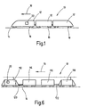
- FIG. 1 schematically shows a track-bound, driven system 10 (hereafter also called train 10), which comprises a total of three vehicles 12.
- train 10 which comprises a total of three vehicles 12.
- at least one of the vehicles 12 is a traction vehicle, that is, via this is a drive energy for moving the system 10 along a route 14 in the direction of travel 16 can be applied.
- the necessary, not shown drive system comprises at least one drive, if necessary also several drives that act on one or more of the wheelsets 18. hereby takes place in a known manner, a transmission of the drive energy of the Wheelsets 18 on the route 14.
- distributed drives are available, that is, the drive power is via wheelsets 18 of several vehicles 12 of a system 10 applied simultaneously.
- the route 14 is known from a arranged on a corresponding substructure track with two rails.
- the route 14 is according to topographic conditions laid, that is, the route 14 may inclines and slopes and arches show different radii.
- the system 10 is a track bound system, independent What kind of drive energy is applied.
- These can be for example rail-bound Systems (high-speed trains, freight trains, trains or the like) or Magnetschwebenmer, where no direct physical contact between the system 10 and the route 14 consists.
- the system 10 includes a device, generally designated 20, for determining a momentary tensile force of the system 10. Under current tensile force, the tensile force understood at any time t, in which the system 10 with any Speed v moves in the direction of travel 16 along the route 14, is required.
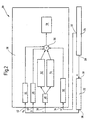
- FIG. 2 shows a block diagram of the device 20.
- the device 20 comprises an inertial Measuring system 22, a speed measuring device 24 and a detection and Evaluation unit 26.
- a first signal output 28 of the speed measuring device 24 is connected to an input 30 of the inertial measuring system 22.
- One second signal output 32 of the speed measuring device 24 is connected to a first Input 34 of the detection and evaluation unit 26 connected.
- a signal output 36 of the inertial measuring system 22 is connected to inputs 38, 40 and 42 of the detection and Evaluation unit 26 connected.
- the detection and evaluation unit 26 comprises circuit components 44, 46, 48, 50, 52, 54, 56 and 58, whose importance and function are discussed in more detail below becomes.
- the device 20 in connection with the system 10 has the following function:
- the instantaneous tensile force of the system 10 is to be determined. This is based on the initial consideration that in order to move the system 10 in the direction of travel 16, this requires a traction that overcomes all of the system 10 acting driving resistances.
- the tractive force is transmitted via the driven wheel sets 18, optionally a plurality of wheel sets 18, which may be distributed over the individual vehicles 12, to the travel path 14 (rails) in the direction of travel 16.
- the number of driven wheelsets 18 act Generalzug devis, the sum of the total tensile force of the system 10.
- the running resistance F wl and the arc resistance F wb are always positive, while the inclination resistance F wn (at Gradient) and the acceleration resistance F wa (during deceleration) can assume positive as well as negative values.
- These individual driving resistances of the system 10 can be determined either for the entire system 10 by means of a device 20. According to a further embodiment, it can be provided that the individual driving resistances for each vehicle 12 of the system 10 are determined separately. For this purpose, a corresponding number of detection and evaluation units 26, each associated with a vehicle 12, would then be required. When determining the individual driving resistances, only one inertial measuring system 22 and one speed measuring device 24 at a certain point of the system 10 are required. At this point, the inputs of the circuit components 44, 46, 48, 52, 54 and 50 are measured and latched. To determine the individual driving resistances, the knowledge of the distances s i of the individual vehicles 12 (or their bogies) is necessary.
- the output variables of the inertial measuring system 22 are then assigned to the circuit components of the individual vehicles, and thus the individual driving resistances are determined.
- the Einzeifahrwiderand for driven and non-powered vehicles can be determined separately.
- the tensile force of a system 10 is determined by when the tensile force for at least one driven vehicle via the determination of the total driving resistance and the required traction for non-powered vehicles by a direct Switzerlandstation, for example, after the known tow hook -Meßhabilit, is determined. Can be detected on the tensile force F to - as already explained - by summation of the so ascertainable individual driving resistance, the total road load of the system 10 over the results then.
- the individual driving resistances are dependent on a number of boundary conditions, which are known in a particular system 10, however.
- the running resistance F wl the arc resistance F wb and the inclination resistance F wn is approximately proportional to the weight G, while the acceleration resistance F wa is linearly connected to the mass m of the system 10.
- the running resistance F wl depends on the aerodynamic shape of the system 10, which can be expressed by the product of air resistance C w and cross-sectional area A in the direction of travel 16.
- the acceleration resistance is determined.
- F wa m ⁇ a x ( ⁇ + 1), where a x is the heading of the system 10 in the direction of travel 16, m is the mass of the system 10 and ⁇ is a weighting factor for a rotational mass fraction of the system 10.
- the mass m and the weighting factor p are known as the constant of the system 10.
- the acceleration a x is provided at the input 42 from the inertial measuring system 22, as will be explained in more detail later.
- the acceleration resistance F wa is proportional to the force that must be applied for a change in speed. In steady state of the system 10, the acceleration resistance F wa is not present. During acceleration of the system 10, an inertial force must be overcome, which can be considered as a damping resistance F wa . In this case, in addition to the translation acceleration of the total mass m, an angular acceleration of the rotating masses of the system 10 must also be taken into account. The rotational energy of the rotating masses can each be replaced by the translational energy of an additional mass.
- the acceleration resistance F wa of the system 10 can thus be determined with knowledge of the mass m of the weighting factor p and the acceleration a x in the direction of travel 16.
- the factor p is, for example, 0.02 to 0.12 for passenger coaches and freight cars, 0.08 to 0.18 for electric railcars, 0.15 to 0.30 for electric locomotives and 0.06 to 0.30 for the average of a locomotive train 0.10.
- the size of the weighting factor p for the rotary mass fraction is weighted according to a total mass m of the system. For empty or loaded (passengers, goods to be transported) systems 10 results in a different weighting factor p of the rotational mass fraction, since the total mass m changes with the load of the system 10.
- the inclination resistance F wn of the system 10 is determined.
- the angle of inclination ⁇ is provided by the inertial measuring system 22 at the input 40 of the detection and evaluation unit 26, as will be explained below.
- the mass m and the gravitational acceleration g are known as constants.
- the sheet resistance F wb of the system 10 is determined.
- the sheet resistance F wb is formed in addition to the running resistance Fwl by the running of the system 10 in track curves.
- the centrifugal forces increase quadratically at increasing speed v and are compensated, for example, in part by civil engineering measures, for example an elevation of the curve-outside rail of the travel path 14.
- the bow resistance F wb is an additional frictional resistance that arises when driving on track curves.
- the cause lies in the unequal way the rigidly connected wheels (inner wheel and outer wheel at Bogenfahrt) of the wheelsets 18.
- the given by the rigid connection of the wheels tracking the wheelsets leads to an inclination of the wheelsets at bow travel, which lead to an increase in the frictional resistance.
- the flange of the outer wheel is pressed at arc travel by the centrifugal force against the rail, so that a further frictional resistance is given.
- the arc resistance F wb is thus dependent on the geometric conditions of the route 14, in particular the radius of curvature r, the gauge of the route 14, the elevation of the outer rail and a track extension in the bow. Further, the arc resistance F wb of the vehicles 12 of the system 10, such as a wheelbase, a Radialein suitkeit the wheelsets 18 dependent. Further, the arc resistance F wb is dependent on a condition of the wheel-rail contact, for example due to wheel flange and / or rail wear, the effect of wheel flange lubrication, wet or dry rails.
- the circuit component becomes 52 and at arc radii r ⁇ 300 m is the circuit component 54 ( Figure 2) of the detection and evaluation 26 activated.
- a signal corresponding to the radius of curvature r lies at the entrance 38 which, as will be explained later, is available from the inertial measuring system 22 is provided.
- the circuit component 50 (FIG. 2) of the detection and evaluation unit 26 is used to determine 45 the running resistance F wl .
- the running resistance F wl is composed of the rolling resistance of the wheels on the guideway 14, the frictional resistance of the bearings and rotating drive components and the air resistance of the system 10.
- the running resistance F wl is always positive.
- the coefficient c 0 indicates the velocity-independent component. This primarily takes into account the rolling friction between the wheel and the rail, the bearing and the spring friction, the friction of the rotating drive parts and the influence of rail joints or the like.
- the coefficient C 1 of the linear member (C 1 ⁇ v) takes into account the movement-inhibiting influence of air currents.
- the coefficient C2 takes into account the air resistance (arerodynamic resistance) of the system 10, which is proportional to the square of the velocity v.
- the numerical values of the coefficients C 0 , C 1 and C 2 are known for known systems 10 and are obtained, for example, during test runs. These coefficients C 0 , C 1 and C 2 can be stored in a table and retrieved depending on the type of vehicles 12 used in the system 10 in consideration of the driving resistance F v .
- an average may be used for simplicity are formed from the coefficients of the individual vehicles 12.
- the running resistance F wl of individual vehicles 12 or of a system 10 can be determined, for example, by a so-called run-out test, in which the system 10 or a vehicle 12 is driven without drive over a defined driving route. In accordance with the effects of friction, the air currents and the aerodynamic resistance, this results in a deceleration of the rolling system 10 or of the vehicles 12, ie a negative acceleration, via which the running resistance F wl can be determined.
- the speed v needed to determine the running resistance F wl is present as a signal at the input 34 and is provided by the speed measuring device 24 , as will be explained below.
- the individual driving resistances F wa , F wn , F wb and F wl are determined and supplied to the formed as a summing circuit component 56. This forms the sum and thus the total driving resistance F w of the system 10.
- tensile force F to equal to the negative driving resistance F w can now be determined via the circuit component 58, the instantaneous tensile force F to the system 10.
- the instantaneous tensile force F can be, for example, in their time characteristic store and / or display, for example on a display screen.
- the acceleration a x in the direction of travel 16 the inclination angle ⁇ , the radius of curvature r and the instantaneous speed v are required. These measured quantities must be provided in real time - to determine the instantaneous total driving resistance F w and thus the instantaneous tractive force F zu .
- the inertial measuring system 22 and the speed measuring device 24 is provided.
- the running resistance F wl is speed-dependent, so that at the input 34, the instantaneous speed signal v must be provided. This is determined by the speed measuring device 24, for example, by detecting the ground speed.
- the driving speed v can be detected, for example, with an incremental encoder on a passive wheel set 18, that is, on a non-drivable and non-brakable wheelset 18. In this case, 18 pulses are generated with each revolution of the wheelset, so that it is possible to determine the speed v in a simple manner with a known extent and measured frequency of the pulses of the incremental encoder.
- the actual speed can also be determined by means of other known methods, for example satellite-based methods (GPS) or radar measuring methods.
- GPS satellite-based methods
- the acceleration a x of the system 10 in the direction of travel 16 can be determined from the speed signal v by differentiation.
- the detection of the distance traveled over the speed v is possible, which is necessary for the separate detection of the driving resistance of the individual vehicles.
- the inertial measuring system 22 has a known per se Gyro arrangement with which the accelerations in all three spatial directions, as well the rotation rates around all spatial axes can be measured.
- the radius of curvature r can look like this the velocity v and the yaw rate about the system vertical axis are determined.
- a determination of the slope and cant of arcs is from the rates of rotation possible around the system longitudinal axis and the system transverse axis.
- centrifugal-based inertial measuring systems 22 Function and construction of such centrifugal-based inertial measuring systems 22 are known, so that in the context of the present description thereto should not be discussed in detail. It is crucial that with such inertial Measuring Systems 22 Accelerations, rotation rates and the positional angles of a moving Body, here the moving system 10, can be determined.
- the inertial measuring system 22 is arranged at a defined location of the system 10. This ensures that this system is fixed, so that the inertial Measuring system 22 is subjected to the same dynamic influences as the System 10.
- FIG. 6 schematically shows a train 10 which can be moved along the route 14 by a traction vehicle 112 designed as an electric locomotive.
- the tensile force F is to be detected to the traction unit 112, which exerts this on the train 10.
- the train 10 comprises in addition to the traction vehicle 112 a measuring carriage 114, a support vehicle 116 and a brake drive vehicle 118.
- the traction unit 112 is coupled to the measuring carriage 114 via a known Buchkraftmeßkupplung 120. This Buchkraftmeßkupplung 120 serves only to verify the instantaneous values supplied by the device 20 to the tension F. During an actual test drive can be dispensed with the arrangement of Switzerlandkraftmeßkupplung 120.
- the brake truck 118 is connected to the backing carriage 116 via a brake power hook 122.
- the brake truck 118 is for simulating the load of a train of a plurality of vehicles 12 (FIG. 1). If the brake drive vehicle 118 is pulled along by the traction vehicle 112, a braking torque acts. The resulting additional braking force is detected by the Bremszugkrafthaken 122 and taken into account in the determination of the acceleration resistance F wa by addition.
- the acceleration resistance F wa the inclination resistance F wn , the arc resistance F wb and the running resistance F wl . determined.
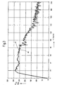
- FIG 3 two traction characteristics are shown, wherein the tensile force F is registered to over the speed v.
- a first tensile force characteristic curve 60 shows the course of the traction force F determined by means of the device 20th
- a second curve 62 shows the course of the tensile force F which has been determined only for verification purposes using the Glaskraftmeßkupplung 120th
- the substantially congruent course of the characteristic curves 60 and 62 it is clear that can be provided by the device 20 and performed by the apparatus 20 method for determining the tensile force F to be very exact values. These are provided without, as in the Switzerlandkraftmeßkupplung 120, a direct tensile force measurement.
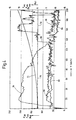
- FIG. 4 shows the course of the individual driving resistances over the speed v for clarification.
- the braking force F br and the damping resistance F wa and on the right the inclination resistance F wn the arc resistance F wb and the running resistance F wl are scaled.
- a characteristic curve 64 illustrates the course of the braking force F br , which takes into account the load simulated via the brake drive vehicle 118.
- a characteristic curve 66 shows the course of the acceleration resistance F wa , which takes into account the force component required for mass acceleration of the train 10.
- a curve 68 represents the course of the inclination resistance F wn taking into account gradients and slopes of the route 14.
- a characteristic curve 70 represents the course of the sheet resistance F wb . The test travel documented here is a route 14 without arcs, so that the characteristic curve 70 essentially runs on the zero line.
- characteristic 72 is entered, which identifies the course of the running resistance F wl . It is clear that with increasing speed v, the running resistance F wl increases exponentially.
- FIG. 5 shows the inclination resistance F wn over the distance s of the travel path 14.
- a first characteristic curve 74 represents the course of the inclination resistances F wn measured by the device 20, while a second characteristic curve 76 represents for comparison the inclination of the travel path 14 taken from a known route file .
- the measured inclination resistance F wn substantially coincides with the actual slope course of the route 14. This results in a further advantage that a route file of routes 14, which are only very expensive to build, for the determination of the inclination resistance F wn per se is not needed.
- a more accurate measurement is possible by means of the instantaneous measurement of the inclination resistance F wn , since here the actual momentary track conditions are taken into account, which may deviate from calculated expected track ratios stored in a track file .
Landscapes
- Chemical & Material Sciences (AREA)
- Engineering & Computer Science (AREA)
- Combustion & Propulsion (AREA)
- Physics & Mathematics (AREA)
- General Physics & Mathematics (AREA)
- Electric Propulsion And Braking For Vehicles (AREA)
- Force Measurement Appropriate To Specific Purposes (AREA)
Claims (16)
- Dispositif de détermination d'une force de traction d'un système entraíné sur voie qui comporte au moins un véhicule, caractérisé en ce que l'effort résistant global (Fw) du système (10) est déterminé à partir d'une somme de différents efforts résistants momentanés, étant pris en compte comme différents efforts résistants une résistance propre (Fwl) , une résistance due aux courbes (Fwb) , une résistance due à l'inclinaison (Fwn) et une résistance due à l'accélération (Fwa) et la force de traction étant déterminée à partir de là suivant la formulec0 - coefficient pour la composante indépendante de la vitessec1 coefficient de l'élément linéairec2 - coefficient pour la résistance due à l'air du systèmev - vitesse momentanée du systèmem - masse du systèmeg - accélération terrestreK - coefficient de largeur de voier - rayon de courbeβ - angle d'inclinaison de la ligneax - accélération du système dans le sens de déplacementρ - facteur de pondération pour la composante de masse rotatoire
- Procédé selon la revendication 1, caractérisé en ce que les différents efforts résistants (Fwl, Fwb, Fwn, Fwa) sont déterminés en tant qu'ensemble pour le système global (10).
- Procédé selon la revendication 1, caractérisé en ce que les différents efforts résistants (Fwl, Fwb, Fwn, Fwa) sont déterminés pour chaque véhicule (12) du système (10) et qu'on détermine à partir de là la somme des différents efforts résistants du système (10).
- Procédé selon l'une quelconque des revendications précédentes, caractérisé en ce que les différents efforts résistants (Fwl, Fwb, Fwn, Fwa) sont déterminés séparément pour les véhicules entraínés (12) et les véhicules non entraínés (12) du système et qu'on détermine à partir de là la somme des différents efforts résistants du système (10).
- Procédé selon l'une quelconque des revendications 1 à 4, caractérisé en ce que les efforts résistants des véhicules non entraínés sont enregistrés par une méthode de mesure connue qui constitue l'état de la technique, par exemple des crochets d'attelage de mesure, et que la force de traction du véhicule moteur est déterminée par le biais de son effort résistant global.
- Dispositif de détermination d'une force de traction d'un système entraíné sur voie qui comporte au moins un véhicule, caractérisé par au moins un système de mesure inertiel (22) disposé fixement dans le système pour la détermination de l'accélération momentanée du système (10) dans les trois directions spatiales et les trois vitesses de rotation momentanées du système (10) autour des trois axes spatiaux, un dispositif de mesure (24) pour la détermination de la vitesse momentanée (v) du système (10) et une unité d'enregistrement et d'exploitation (26) pour la détermination d'un effort résistant global momentané (Fw) du système (10) à partir d'une somme de différents efforts résistants momentanés, sachant qu'il faut tenir compte comme différents efforts résistants d'une résistance propre (Fw), d'une résistance due aux courbes (Fwb), d'une résistance due à l'inclinaison (Fwn) et d'une résistance due à l'accélération (Fwa) et que la force de traction Fzu doit être déterminée suivant la formulec0 - coefficient pour la composante indépendante de la vitesseC1 - coefficient de l'élément linéairec2 - coefficient pour la résistance due à l'air du systèmev - vitesse momentanée du systèmem - masse du systèmeg - accélération terrestreK - coefficient de largeur de voier - rayon de courbeβ - angle d'inclinaison de la ligneax - accélération du système dans le sens de déplacementρ - facteur de pondération pour la partie de masse rotatoire
- Dispositif selon la revendication 6, caractérisé en ce que l'unité d'enregistrement et d'exploitation (26) comprend une composante de circuit (44) pour l'enregistrement d'une résistance momentanée due à l'accélération (Fwa).
- Dispositif selon l'une quelconque des revendications précédentes, caractérisé en ce que l'unité d'enregistrement et d'exploitation (26) comprend une composante de circuit (46) pour l'enregistrement d'une résistance momentanée due à l'inclinaison (Fwn).
- Dispositif selon l'une quelconque des revendications précédentes, caractérisé en ce que l'unité d'enregistrement et d'exploitation (26) comprend des composantes de circuit (48, 52, 54) pour l'enregistrement d'une résistance momentanée due aux courbes (Fwb).
- Dispositif selon l'une quelconque des revendications précédentes, caractérisé en ce que l'unité d'enregistrement et d'exploitation (26) comprend une composante de circuit (50) pour l'enregistrement d'une résistance propre momentanée (Fwl).
- Dispositif selon l'une quelconque des revendications précédentes, caractérisé en ce que l'unité d'enregistrement et d'exploitation (26) comprend une composante de circuit (56) qui permet de totaliser les résistances dues à l'accélération (Fwa), les résistances dues à l'inclinaison (Fwn) , les résistances dues aux courbes (Fwb) et les résistances propres (Fwl) momentanées pour obtenir l'effort résistant global (Fw) momentané.
- Dispositif selon l'une quelconque des revendications précédentes, caractérisé en ce qu'on peut déterminer, au moyen du système de mesure inertiel (22), un angle d'inclinaison (β), un rayon de courbe (r) d'une ligne (14) du système (10) et une accélération (ax) du système dans le sens de déplacement (16).
- Dispositif selon l'une quelconque des revendications précédentes, caractérisé en ce que l'unité d'enregistrement et d'exploitation (26) comprend une composante de circuit (58) pour la détermination de la force de traction (Fzu) à partir de l'effort résistant global (Fw).
- Dispositif selon l'une quelconque des revendications précédentes, caractérisé en ce que le système (10) est un train sur rail comprenant au moins un véhicule moteur.
- Dispositif selon l'une quelconque des revendications 6 à 14, caractérisé en ce que le système (10) est un train à suspension magnétique.
- Dispositif selon l'une quelconque des revendications précédentes, caractérisé en ce que le système (10) possède une propulsion partagée.
Applications Claiming Priority (2)
| Application Number | Priority Date | Filing Date | Title |
|---|---|---|---|
| DE19955010A DE19955010C2 (de) | 1999-11-16 | 1999-11-16 | Verfahren und Vorrichtung zur Ermittlung einer Zugkraft eines spurgebundenen, angetriebenen Systems |
| DE19955010 | 1999-11-16 |
Publications (2)
| Publication Number | Publication Date |
|---|---|
| EP1111359A1 EP1111359A1 (fr) | 2001-06-27 |
| EP1111359B1 true EP1111359B1 (fr) | 2005-02-02 |
Family
ID=7929165
Family Applications (1)
| Application Number | Title | Priority Date | Filing Date |
|---|---|---|---|
| EP00124871A Expired - Lifetime EP1111359B1 (fr) | 1999-11-16 | 2000-11-15 | Procédé et dispositif pour déterminer la force de traction d'un système entraíné et guidé sur une voie |
Country Status (3)
| Country | Link |
|---|---|
| EP (1) | EP1111359B1 (fr) |
| AT (1) | ATE288582T1 (fr) |
| DE (2) | DE19955010C2 (fr) |
Cited By (1)
| Publication number | Priority date | Publication date | Assignee | Title |
|---|---|---|---|---|
| US8185263B2 (en) | 2008-11-24 | 2012-05-22 | General Electric Company | Apparatus and method for estimating resistance parameters and weight of a train |
Families Citing this family (8)
| Publication number | Priority date | Publication date | Assignee | Title |
|---|---|---|---|---|
| DE10146757B4 (de) * | 2001-09-22 | 2004-03-04 | Bayerische Motoren Werke Ag | Verfahren zur Simulation einer Hangabtriebskraft an einem in der Ebene bewegten Kraftfahrzeug |
| DE10159957B4 (de) * | 2001-12-06 | 2006-11-02 | Db Fernverkehr Ag | Onboard-Bestimmung fahrdynamischer Daten |
| DE102006005206B3 (de) * | 2006-02-02 | 2007-09-13 | Deutsches Zentrum für Luft- und Raumfahrt e.V. | Einrichtung zur Überwachung der Zugvollständigkeit |
| DE102006005207B4 (de) * | 2006-02-02 | 2007-10-18 | Deutsches Zentrum für Luft- und Raumfahrt e.V. | Vorrichtung zur fahrzeugseitigen Überwachung der Zugvollständigkeit |
| DE102007061168A1 (de) * | 2007-12-17 | 2009-06-25 | Rwe Power Ag | Verfahren zur Bestimmung der Zugmasse eines Zugverbandes |
| BRPI0916090A2 (pt) * | 2008-11-24 | 2015-11-10 | Gen Electric | "método de controle para controlar um veículo usado fora de rodovias e método de controle para controlar uma composição de veículo |
| CN107843370B (zh) * | 2017-09-01 | 2020-07-17 | 中车青岛四方机车车辆股份有限公司 | 一种轨道列车运行阻力的测试装置及方法 |
| CN113741404B (zh) * | 2021-09-26 | 2022-11-11 | 广州文远知行科技有限公司 | 模拟车辆负载的控制方法、装置、系统及存储介质 |
Family Cites Families (3)
| Publication number | Priority date | Publication date | Assignee | Title |
|---|---|---|---|---|
| DE3427907A1 (de) * | 1984-07-28 | 1986-01-30 | Robert Bosch Gmbh, 7000 Stuttgart | Vorrichtung zum mechanischen messen und zum regeln der zugkraft einer zugmaschine |
| DE4218929C1 (fr) * | 1992-06-10 | 1993-09-09 | Deutsche Bundesbahn, Vertreten Durch Das Bundesbahn-Zentralamt Minden (Westf.), 4950 Minden, De | |
| DE4228413A1 (de) * | 1992-08-26 | 1994-03-03 | Bosch Gmbh Robert | Verfahren und Vorrichtung zur Bestimmung von Fahrzeugmasse und Fahrwiderstand |
-
1999
- 1999-11-16 DE DE19955010A patent/DE19955010C2/de not_active Expired - Fee Related
-
2000
- 2000-11-15 AT AT00124871T patent/ATE288582T1/de active
- 2000-11-15 EP EP00124871A patent/EP1111359B1/fr not_active Expired - Lifetime
- 2000-11-15 DE DE50009412T patent/DE50009412D1/de not_active Expired - Lifetime
Cited By (1)
| Publication number | Priority date | Publication date | Assignee | Title |
|---|---|---|---|---|
| US8185263B2 (en) | 2008-11-24 | 2012-05-22 | General Electric Company | Apparatus and method for estimating resistance parameters and weight of a train |
Also Published As
| Publication number | Publication date |
|---|---|
| DE19955010C2 (de) | 2002-05-16 |
| ATE288582T1 (de) | 2005-02-15 |
| DE50009412D1 (de) | 2005-03-10 |
| EP1111359A1 (fr) | 2001-06-27 |
| DE19955010A1 (de) | 2001-06-07 |
Similar Documents
| Publication | Publication Date | Title |
|---|---|---|
| EP1430276B1 (fr) | Procede de determination de la masse d'un vehicule avec prise en compte de differentes situations de conduite | |
| DE102011113086B4 (de) | Bremskrafterfassung für dynamische Bremsen eines Schienenfahrzeugs | |
| DE69529474T2 (de) | Spurdatenspeicherung in einem positionsgeregelten neigbaren system | |
| DE69510871T2 (de) | Steuerverfahren zur Lenkung von Laufwerken mit einstellbaren Rädern einer auf Schienen fahrenden Einheit und dieses Verfahren nutzende Einheit | |
| DE102017213970A1 (de) | Verfahren und Vorrichtung zum Bestimmen von Veränderungen im längsdynamischen Verhalten eines Schienenfahrzeugs | |
| EP3676138B1 (fr) | Procédé et dispositif de détermination de valeurs réelles réeles liées au freinage d'un véhicule ferroviaire pour effectuer un freinage à décélération régulée avec capteurs centralisés | |
| EP1111359B1 (fr) | Procédé et dispositif pour déterminer la force de traction d'un système entraíné et guidé sur une voie | |
| CH674180A5 (fr) | ||
| WO2016058727A1 (fr) | Diagnostic de l'état des roues d'un véhicule ferroviaire | |
| DE19801311A1 (de) | Schienengebundene Instandhaltungsmaschine | |
| EP2872368B1 (fr) | Procédé pour le freinage d'un véhicule | |
| DE102019211939A1 (de) | Verfahren zur Bestimmung einer Wagengeschwindigkeit eines Wagens | |
| EP3676139A1 (fr) | Procédé et dispositif de détermination de valeurs réelles d'un véhicule ferroviaire concernant le freinage pour la mise en oeuvre d'un freinage à décélération controlée à capteurs repartis | |
| DE10159957B4 (de) | Onboard-Bestimmung fahrdynamischer Daten | |
| EP2378263B1 (fr) | Système et procédé de détermination du centre de gravité de la masse dans des véhicules sur rails | |
| EP0647553B1 (fr) | Système de guidage et méthode pour la commande de la pente latérale d'un véhicule ferroviaire | |
| WO2018215538A1 (fr) | Procédé pour repérer un déraillement d'un véhicule ferroviaire | |
| DE102006006365A1 (de) | Verfahren und Vorrichtung zur Längsbewegungssteuerung eines Fahrzeugs | |
| EP0826548A1 (fr) | Méthode de régulation d'entraínement électrique pour véhicules ferroviaires | |
| EP1279581A1 (fr) | Dispositif de mesure externe de la longueur d'un train | |
| DE102023209096B4 (de) | Verfahren, Schienenfahrzeug und System für eine Spurkranzschmierung | |
| DE102006005206B3 (de) | Einrichtung zur Überwachung der Zugvollständigkeit | |
| DE102023200761A1 (de) | Verfahren und Einrichtung zum Erzeugen eines einen Zustand eines Fahrzeugs anzeigenden Zustandssignals | |
| DE1906184A1 (de) | Verfahren und Anordnung zur Korrektur des Zugkraftsollwertes von Triebfahrzeugen in Abhaengigkeit von der Wagenbelastung | |
| DE102023201208A1 (de) | Verfahren und Einrichtung zum Erzeugen eines einen Zustand eines Fahrzeugs anzeigenden Zustandssignals |
Legal Events
| Date | Code | Title | Description |
|---|---|---|---|
| PUAI | Public reference made under article 153(3) epc to a published international application that has entered the european phase |
Free format text: ORIGINAL CODE: 0009012 |
|
| AK | Designated contracting states |
Kind code of ref document: A1 Designated state(s): AT CH DE FR LI SE |
|
| AX | Request for extension of the european patent |
Free format text: AL;LT;LV;MK;RO;SI |
|
| 17P | Request for examination filed |
Effective date: 20011207 |
|
| AKX | Designation fees paid |
Free format text: AT CH DE FR LI SE |
|
| RAP1 | Party data changed (applicant data changed or rights of an application transferred) |
Owner name: DB REISE & TOURISTIK AG Owner name: DB REGIO AG |
|
| 17Q | First examination report despatched |
Effective date: 20030916 |
|
| RAP1 | Party data changed (applicant data changed or rights of an application transferred) |
Owner name: DB REISE & TOURISTIK AG |
|
| GRAP | Despatch of communication of intention to grant a patent |
Free format text: ORIGINAL CODE: EPIDOSNIGR1 |
|
| GRAS | Grant fee paid |
Free format text: ORIGINAL CODE: EPIDOSNIGR3 |
|
| GRAA | (expected) grant |
Free format text: ORIGINAL CODE: 0009210 |
|
| AK | Designated contracting states |
Kind code of ref document: B1 Designated state(s): AT CH DE FR LI SE |
|
| REG | Reference to a national code |
Ref country code: CH Ref legal event code: EP Ref country code: CH Ref legal event code: NV Representative=s name: RIEDERER HASLER & PARTNER PATENTANWAELTE AG |
|
| REF | Corresponds to: |
Ref document number: 50009412 Country of ref document: DE Date of ref document: 20050310 Kind code of ref document: P |
|
| REG | Reference to a national code |
Ref country code: SE Ref legal event code: TRGR |
|
| ET | Fr: translation filed | ||
| PLBE | No opposition filed within time limit |
Free format text: ORIGINAL CODE: 0009261 |
|
| STAA | Information on the status of an ep patent application or granted ep patent |
Free format text: STATUS: NO OPPOSITION FILED WITHIN TIME LIMIT |
|
| 26N | No opposition filed |
Effective date: 20051103 |
|
| PGFP | Annual fee paid to national office [announced via postgrant information from national office to epo] |
Ref country code: AT Payment date: 20101119 Year of fee payment: 11 |
|
| REG | Reference to a national code |
Ref country code: DE Ref legal event code: R081 Ref document number: 50009412 Country of ref document: DE Owner name: DEUTSCHE BAHN AG, DE Free format text: FORMER OWNER: DB FERNVERKEHR AG, 60326 FRANKFURT, DE Effective date: 20110221 |
|
| PGFP | Annual fee paid to national office [announced via postgrant information from national office to epo] |
Ref country code: FR Payment date: 20111125 Year of fee payment: 12 Ref country code: SE Payment date: 20111122 Year of fee payment: 12 Ref country code: CH Payment date: 20111124 Year of fee payment: 12 |
|
| PGFP | Annual fee paid to national office [announced via postgrant information from national office to epo] |
Ref country code: DE Payment date: 20120125 Year of fee payment: 12 |
|
| REG | Reference to a national code |
Ref country code: CH Ref legal event code: PL |
|
| REG | Reference to a national code |
Ref country code: AT Ref legal event code: MM01 Ref document number: 288582 Country of ref document: AT Kind code of ref document: T Effective date: 20121115 |
|
| PG25 | Lapsed in a contracting state [announced via postgrant information from national office to epo] |
Ref country code: SE Free format text: LAPSE BECAUSE OF NON-PAYMENT OF DUE FEES Effective date: 20121116 Ref country code: LI Free format text: LAPSE BECAUSE OF NON-PAYMENT OF DUE FEES Effective date: 20121130 Ref country code: AT Free format text: LAPSE BECAUSE OF NON-PAYMENT OF DUE FEES Effective date: 20121115 Ref country code: CH Free format text: LAPSE BECAUSE OF NON-PAYMENT OF DUE FEES Effective date: 20121130 |
|
| REG | Reference to a national code |
Ref country code: FR Ref legal event code: ST Effective date: 20130731 |
|
| REG | Reference to a national code |
Ref country code: DE Ref legal event code: R119 Ref document number: 50009412 Country of ref document: DE Effective date: 20130601 |
|
| PG25 | Lapsed in a contracting state [announced via postgrant information from national office to epo] |
Ref country code: DE Free format text: LAPSE BECAUSE OF NON-PAYMENT OF DUE FEES Effective date: 20130601 |
|
| PG25 | Lapsed in a contracting state [announced via postgrant information from national office to epo] |
Ref country code: FR Free format text: LAPSE BECAUSE OF NON-PAYMENT OF DUE FEES Effective date: 20121130 |