EP1111421A2 - Montage d'un module optique à puce retournée et alignement utilisant des rainures et des fibres optiques - Google Patents
Montage d'un module optique à puce retournée et alignement utilisant des rainures et des fibres optiques Download PDFInfo
- Publication number
- EP1111421A2 EP1111421A2 EP00311594A EP00311594A EP1111421A2 EP 1111421 A2 EP1111421 A2 EP 1111421A2 EP 00311594 A EP00311594 A EP 00311594A EP 00311594 A EP00311594 A EP 00311594A EP 1111421 A2 EP1111421 A2 EP 1111421A2
- Authority
- EP
- European Patent Office
- Prior art keywords
- package
- optical
- optical element
- groove portion
- positioning groove
- Prior art date
- Legal status (The legal status is an assumption and is not a legal conclusion. Google has not performed a legal analysis and makes no representation as to the accuracy of the status listed.)
- Granted
Links
- 230000003287 optical effect Effects 0.000 title claims abstract description 216
- 239000013307 optical fiber Substances 0.000 title claims abstract description 101
- 239000000758 substrate Substances 0.000 claims abstract description 126
- 238000003780 insertion Methods 0.000 claims description 22
- 230000037431 insertion Effects 0.000 claims description 22
- 239000011347 resin Substances 0.000 claims description 14
- 229920005989 resin Polymers 0.000 claims description 14
- 238000000465 moulding Methods 0.000 description 10
- 238000006073 displacement reaction Methods 0.000 description 8
- 239000000835 fiber Substances 0.000 description 8
- 239000000853 adhesive Substances 0.000 description 7
- 230000001070 adhesive effect Effects 0.000 description 7
- 239000004065 semiconductor Substances 0.000 description 5
- 230000015572 biosynthetic process Effects 0.000 description 4
- 230000008878 coupling Effects 0.000 description 4
- 238000010168 coupling process Methods 0.000 description 4
- 238000005859 coupling reaction Methods 0.000 description 4
- 238000000034 method Methods 0.000 description 4
- 238000004891 communication Methods 0.000 description 3
- 230000007613 environmental effect Effects 0.000 description 2
- 239000000919 ceramic Substances 0.000 description 1
- 238000013461 design Methods 0.000 description 1
- 230000000694 effects Effects 0.000 description 1
- PCHJSUWPFVWCPO-UHFFFAOYSA-N gold Chemical compound [Au] PCHJSUWPFVWCPO-UHFFFAOYSA-N 0.000 description 1
- 239000010931 gold Substances 0.000 description 1
- 229910052737 gold Inorganic materials 0.000 description 1
- 238000001746 injection moulding Methods 0.000 description 1
- 238000004519 manufacturing process Methods 0.000 description 1
- 239000002184 metal Substances 0.000 description 1
- 229910052751 metal Inorganic materials 0.000 description 1
- 238000012544 monitoring process Methods 0.000 description 1
- 238000012545 processing Methods 0.000 description 1
- 239000010453 quartz Substances 0.000 description 1
- VYPSYNLAJGMNEJ-UHFFFAOYSA-N silicon dioxide Inorganic materials O=[Si]=O VYPSYNLAJGMNEJ-UHFFFAOYSA-N 0.000 description 1
- 238000012546 transfer Methods 0.000 description 1
- 238000001721 transfer moulding Methods 0.000 description 1
Images


Classifications
-
- G—PHYSICS
- G02—OPTICS
- G02B—OPTICAL ELEMENTS, SYSTEMS OR APPARATUS
- G02B6/00—Light guides; Structural details of arrangements comprising light guides and other optical elements, e.g. couplings
- G02B6/24—Coupling light guides
- G02B6/42—Coupling light guides with opto-electronic elements
- G02B6/4201—Packages, e.g. shape, construction, internal or external details
- G02B6/4219—Mechanical fixtures for holding or positioning the elements relative to each other in the couplings; Alignment methods for the elements, e.g. measuring or observing methods especially used therefor
- G02B6/4228—Passive alignment, i.e. without a detection of the degree of coupling or the position of the elements
- G02B6/423—Passive alignment, i.e. without a detection of the degree of coupling or the position of the elements using guiding surfaces for the alignment
- G02B6/4231—Passive alignment, i.e. without a detection of the degree of coupling or the position of the elements using guiding surfaces for the alignment with intermediate elements, e.g. rods and balls, between the elements
-
- G—PHYSICS
- G02—OPTICS
- G02B—OPTICAL ELEMENTS, SYSTEMS OR APPARATUS
- G02B6/00—Light guides; Structural details of arrangements comprising light guides and other optical elements, e.g. couplings
- G02B6/24—Coupling light guides
- G02B6/42—Coupling light guides with opto-electronic elements
- G02B6/4201—Packages, e.g. shape, construction, internal or external details
- G02B6/4219—Mechanical fixtures for holding or positioning the elements relative to each other in the couplings; Alignment methods for the elements, e.g. measuring or observing methods especially used therefor
- G02B6/4236—Fixing or mounting methods of the aligned elements
- G02B6/424—Mounting of the optical light guide
- G02B6/4243—Mounting of the optical light guide into a groove
-
- G—PHYSICS
- G02—OPTICS
- G02B—OPTICAL ELEMENTS, SYSTEMS OR APPARATUS
- G02B6/00—Light guides; Structural details of arrangements comprising light guides and other optical elements, e.g. couplings
- G02B6/24—Coupling light guides
- G02B6/42—Coupling light guides with opto-electronic elements
- G02B6/4201—Packages, e.g. shape, construction, internal or external details
- G02B6/4219—Mechanical fixtures for holding or positioning the elements relative to each other in the couplings; Alignment methods for the elements, e.g. measuring or observing methods especially used therefor
- G02B6/4228—Passive alignment, i.e. without a detection of the degree of coupling or the position of the elements
- G02B6/423—Passive alignment, i.e. without a detection of the degree of coupling or the position of the elements using guiding surfaces for the alignment
-
- G—PHYSICS
- G02—OPTICS
- G02B—OPTICAL ELEMENTS, SYSTEMS OR APPARATUS
- G02B6/00—Light guides; Structural details of arrangements comprising light guides and other optical elements, e.g. couplings
- G02B6/24—Coupling light guides
- G02B6/42—Coupling light guides with opto-electronic elements
- G02B6/4201—Packages, e.g. shape, construction, internal or external details
- G02B6/4249—Packages, e.g. shape, construction, internal or external details comprising arrays of active devices and fibres
-
- G—PHYSICS
- G02—OPTICS
- G02B—OPTICAL ELEMENTS, SYSTEMS OR APPARATUS
- G02B6/00—Light guides; Structural details of arrangements comprising light guides and other optical elements, e.g. couplings
- G02B6/24—Coupling light guides
- G02B6/42—Coupling light guides with opto-electronic elements
- G02B6/4292—Coupling light guides with opto-electronic elements the light guide being disconnectable from the opto-electronic element, e.g. mutually self aligning arrangements
Definitions
- the present invention relates to an optical module used in optical communications or data communications.
- An optical module in which an optical element mounting substrate for mounting optical elements are arranged in a package has been used in optical communications or the like. Recently, in order to meet a requirement to save cost for the optical module, an optical module whose package is made of resin has heretofore been developed.
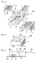
- Fig. 7A is an exploded view of an optical module proposed in Japanese Patent Application No. Hei 9-007021 as an example of this type optical module.
- Fig. 7B is a perspective view of an example of an outer appearance of the optical module.
- an array type optical element 1 in which, for example, light emitting portions or light receiving portions are arranged in an array is mounted on and fixed to an optical element mounting substrate 2.
- a pattern of electric signal wirings 10 is formed on a mounting surface (substrate surface) 28 of this optical element 1.
- V-shaped grooves 9 (having a V-shape in cross section) as at least one pair of groove portions for positioning on the substrate side are formed on both sides with respect to the electric signal wirings 10.
- the optical elements there are various kinds of the optical elements 1. For example, there is a module in which a semiconductor laser chip having four channels for emitting an optical signal is arranged on a substrate, a module in which a photodiode chip for receiving an optical signal is arranged instead of the semiconductor laser chip, a module in which the semiconductor laser chip is arranged in the same manner and a photodiode chip for monitoring a light emission condition of the semiconductor laser chip is provided behind the semiconductor laser chip and the like.
- the optical element that meets the specification is selected and mounted on and fixed to the optical element mounting substrate 2.
- a package 4 is made of resin to have a base portion 31 and a side wall 32 having a substantially L-shape (an L-shape in cross section) that is in an upright position at an end face of the base portion 31. At least one (four in case of Fig. 7A) input/output optical fiber insertion hole 6 is formed in the side wall 32 of this package 4.
- Input/output optical fibers 7 are inserted into the input/output optical fiber insertion holes 6, respectively.
- Each of the input/output optical fibers 7 is a short optical fiber for at least one of the optical input to the optical element 1 and the optical output of a beam outputted from the optical element 1 to the outside.
- a positioning projection 18 is formed in a position corresponding to each of the V-shaped grooves 9 of the optical element mounting substrate 2 in the package 4.
- the substrate surface 28 of the optical element mounting substrate 2 is caused to face the surface on which the projections 18 are formed in the package 4, with the substrate surface 28 of the optical element mounting substrate 2 being directed downwardly (in Fig. 7A), the optical element mounting substrate 2 is caused to overlap on the base portion 31 of the package 4, and the projections 18 are inserted and fitted into the V-shaped grooves 9.
- Fig. 8 is a cross-sectional view showing an fitted condition of the projections 18 into the V-shaped grooves 9.
- the cross section of the projections 18 is formed into an arcuate shape at their ends, and the ends contact the groove surfaces of the V-shaped grooves 9. Then, thus, the projections 18 are inserted and fitted into the V-shaped grooves 9 so that the package 4 and the optical element mounting substrate 2 are positioned with each other and the array type optical element 1 and the input/output optical fibers 7 are centered and optically coupled to each other.
- the region (indicated by reference character A in Fig. 7A) between an inner wall surface 32a of the side wall 32 of the package 4 and the optical element 1 is sealed with resin.
- the input/output optical fibers 7 are bonded and fixed to the package 4, at the same time, the optical element 1 of the optical element mounting substrate 2 as a whole is covered by the resin to be sealed. Furthermore, the optical element mounting substrate 2 is fixed to the package 4.
- the package 4 in which the optical element mounting substrate 2 is provided is mounted on a lead frame package 11 with the optical element mounting substrate 2 being directed downwardly as indicated by the arrow C in Fig. 7A, and fixed by adhesives 30.
- the optical module 100 shown in Figs. 7A and 7B is constructed as described above. This optical module 100 is constructed so as to be electrically connectable to a circuit of a mounting substrate (not shown) through a plurality of lead terminals 17 formed in the lead frame package 11.
- reference numeral 20 in Figs. 7A and 7B indicates an opening portion, which is a hole for wire bonding (lines made of gold are arranged from the optical element mounting substrate 2 to the lead frame package 11) and injecting the adhesives 30.
- the optical module 100 only the projections 18 of the package 4 are inserted and fitted in the V-shaped grooves 9 of the optical element mounting substrate 2 so that the array type optical element 1 and the input/output optical fibers 7 are centered and optically coupled to each other.
- the optical module may optically and directly coupling the array type optical element 1 and the input/output optical fibers 7 with each other without any lens without using an expensive device.
- the resin made package 4 is molded by transfer molding, injection molding of the resin or the like, there is a problem in that it is technically difficult to form the projections 18 into a desired shape, for example, an arcuate shape having a diameter of about 125 ⁇ m.
- the resin forming the package 4 is caused to flow into a mold 33 having a groove 33a for forming the projection 18 and cured.
- the groove 33a of the mold 33 it is necessary to transfer the groove 33a of the mold 33 exactly with the precision of ⁇ 1 ⁇ m.
- a high processing technique is required. Also, in view of the fact that it is difficult to exactly evaluate the dimension of the machined mold, it is difficult to enhance the dimensional precision of the mold 33 by feeding back the information of the dimensional error of the molded product.
- the present invention has been made in view of the above, and an object of the present invention is therefore to provide an optical module in which an optical element mounting substrate and a package may be arranged exactly with each other.
- an optical module having an optical element mounting substrate on which an optical element is mounted, and a package made of resin, on which the optical element mounting substrate is arranged, characterized in that a substrate side positioning groove portion is formed in a substrate surface of the optical element mounting substrate, a package side positioning groove portion is formed in the package, the package side positioning groove portion facing the substrate side positioning groove portion by arranging the optical element mounting substrate to face the package, and a positioning member is inserted between the package side positioning groove portion and the substrate positioning groove portion which face each other.
- an optical module provided with the structure according to the first aspect of the invention, and characterized in that at least one of the substrate side positioning groove portion and the package side positioning groove portion is a groove having a substantially V-shaped groove in cross section.
- an optical module provided with the structure according to the first aspect of the invention, and characterized in that at least one of the substrate side positioning groove portion and the package side positioning groove portion is a groove having an arcuate groove in cross section.
- an optical module provided with the structure according to the first aspect of the invention according to the first aspect of the invention, and characterized in that at least one of the substrate side positioning groove portion and the package side positioning groove portion has such a shape that the groove portion may engage with the positioning member with almost no gap.
- an optical module provided with the structure according to any one of the first to fourth aspects of the invention, and characterized in that the positioning member is a columnar member.
- an optical module provided with the structure according to any one of the first to fifth aspects of the invention, and characterized in that a linear expansion coefficient of the positioning member is 1x10 -6 /K or less.
- an optical module provided with the structure according to any one of the first to sixth aspects of the invention, and characterized in that the positioning member is an optical fiber.
- an optical module provided with the structure according to any one of the first to seventh aspects of the invention, and characterized in that the substrate side positioning groove portions are formed on both sides of the optical element.
- an optical module provided with the structure according to any one of the first to eighth aspects of the invention, and characterized in that a length of a part of the positioning member clamped between the optical element mounting substrate and the package is one third or more of the substrate side positioning groove portion.
- an optical module provided with the structure according to any one of the first to ninth aspects of the invention, and characterized in that the package has a base portion in which the package side positioning groove is formed, and a side wall which is formed in an upright condition at an end face of the base portion, and a hole for insertion of the positioning member is formed so as to be continuous with the package side positioning groove portion.
- an optical module provided with the structure according to any one of the first to tenth aspects of the invention, and characterized in that an optical fiber to be optically coupled to the optical element is mounted on the package, and the optical fiber and the positioning member are arranged such that they are substantially in parallel with each other along their longitudinal direction and the centers thereof are substantially in the same flat plane.
- an optical module provided with the structure according to any one of the first to eleventh aspects of the invention, and characterized in that the optical module further comprises an optical fiber to be optically coupled to the optical element, wherein the optical fiber is optically coupled directly to the optical element.
- a substrate side positioning groove portion is provided in a substrate surface of the optical element mounting substrate, a package side position groove portion is formed in the package, the optical element mounting substrate and the package are arranged with the substrate side positioning groove portion and the package side positioning groove portion facing each other, and a positioning member is inserted between the package side positioning groove portion and substrate positioning groove portion which face each other.
- the package positioning portion is in the form of a groove as described above.
- the substantially V-shaped groove or the arcuate groove may readily be formed with high precision. It is therefore possible to enhance the positioning precision of the optical element mounting substrate and the package.
- the grooves are intimately fitted with the positioning member so that the positional displacement of the positioning member to the positioning groove portions may be avoided. It is thus possible to considerably enhance the positioning precision of the optical element mounting substrate and the package.
- the positioning member is the columnar member
- the columnar positioning member may be arranged in the substantially V-shaped groove without any displacement.
- the thermal expansion or the thermal shrinkage of the positioning member due to the temperature change is very small whereby it is possible to substantially suppress the positional displacement of the package and the optical element mounting substrate caused by the temperature change.
- the positioning member is the optical fiber
- the optical fiber is in the form of a columnar shape with its linear expansion coefficient of 1x10 -6 /K or less.
- the optical fiber as the positioning member is inserted and fitted between the substrate side positioning groove portion and the package side positioning groove portion, and the package may be positioned to the optical element mounting substrate as designed.
- the substrate side positioning portions are formed on both sides of the optical element, it is possible to arrange the optical element to the package in the position as designed. It is thus possible to considerably enhance the optical coupling rate of, for example, the optical element and the optical fiber that is the object to be optically coupled to and mounted on the package.
- the length of the part of the positioning member clamped between the optical element mounting substrate and the package is one third or more of the full length of the substrate side positioning groove portion, there is no fear that the positioning member is too short and tilted to the package. It is thus possible to align the package and the optical element mounting substrate to each other without fail.
- the positioning member is inserted and arranged into the package side positioning groove portion through the hole of the side wall of the package, so that the positioning member may be positioned in a set position with ease.
- optical fiber to be optically coupled to the optical element is fixed to the package, and the optical fiber and the positioning member are arranged such that they are substantially in parallel with each other along their longitudinal direction and the centers thereof are substantially in the same flat plane, it is possible to position the optical element and the fiber to each other with the optimum positioning precision and to perform the very good optical coupling of the optical element and the fiber.
- the present invention it is possible to position the optical element and the optical fiber to each other with very high precision. It is thus possible to optically couple the optical element and the optical fiber directly to each other without any lens and without using an expensive device to thereby reduce the size of the optical module.
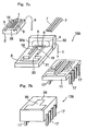
- Fig. 1A is an exploded view of an optical module according to an embodiment of the present invention.
- Fig. 1B is a perspective view of an example of an outer appearance of the optical module 200 shown in Fig. 1A.
- Fig. 1C is a side elevational view of an example of a state in which another optical component 400 is connected to the optical module 200 shown in Fig. 1A.
- Fig. 2A is a cross-sectional view taken along an extension line of a straight line D shown in Fig. 1A, showing a state in which an optical element mounting substrate 2 is arranged on and fixed to a package 4 of the optical module 200.
- Fig. 2B is a cross-sectional view taken along the line A-A' of Fig. 2A
- Fig. 2C is a cross-sectional view taken along the line B-B' of Fig. 2A, showing this state, respectively.
- the optical module 200 shown in these drawings is composed of the optical element mounting substrate 2, the package 4 and a lead frame package 11.
- the structure of each of the optical element mounting substrate 2 and the lead frame package 11 is the same as that of the conventional case.
- This embodiment is different from the conventional case in that, as shown in Figs. 1A and 2C, positioning grooves are provided in the optical element mounting substrate 2 and the package 4, respectively, and positioning members 3 for positional alignment are provided between positioning groove portions 5 of the package 4 and positioning groove portions 9 of the optical element mounting substrate 2.
- each of the grooves 5 having an arcuate cross-section as shown in Fig. 3 is formed as the package side positioning groove portion at a position corresponding to a V-shaped groove 9 of the optical element mounting substrate 2 in the package 4.
- a mounting surface (substrate surface) 28 of the optical element 1 is caused to face the surface of the package 4 where the arcuate groove 5 is formed with the substrate surface 28 being directed downwardly in Fig. 1A, and the optical element 1 is overlapped on the package 4.
- the V-shaped groove 9 of the optical element mounting substrate 2 and the arcuate groove 5 of the package 4 are arranged to face each other.
- the positioning optical fiber 3 optical fiber that is the common positioning member is inserted between the V-shaped groove 9 and arcuate groove 5 which face each other.
- Fig. 3 shows, in cross section, an engagement state of the V-shaped groove 9 and arcuate groove 5 with the positioning optical fiber 3.
- the arcuate groove 5 is formed to have substantially the same diameter as the outer diameter of the positioning optical fiber 3.
- the positioning optical fiber 3 is contacted at two positions with the groove surface of the V-shaped groove 9 and engaged with the arcuate groove 5 with almost no gap.
- the package 4 and the optical element mounting substrate 2 are aligned with each other by the positioning optical fiber 3 and the arcuate groove 5 and V-shaped groove 9.
- the array type optical element 1 and the input/output optical fibers 7 are optically coupled with each other in a centered condition.
- a single mode fiber or the like that is generally used is used as the positioning optical fiber 3.
- This single mode fiber is very thin to have a diameter of, for example, about 125 ⁇ m. For this reason, this single mode fiber is used as the positioning optical fiber 3 to thereby make it possible to miniaturize the optical module 200.
- the single mode fiber has a high molding precision although it is thin as described above, it is possible to considerably enhance the positioning precision.
- the single mode fiber is generally made of quartz, the linear expansion coefficient is very small at 4x10 -7 /K or less. It is thus possible to prevent the positional displacement of the package 4 and the optical element mounting substrate 2 due to the temperature change.
- the positioning optical fiber 3 is formed into a columnar shape, it is easy to perform the positioning by the V-shaped grooves 9.
- the arcuate groove 5 may be formed as follows because the positioning optical fiber 3 has such a shape that it may engage with the groove with almost no gap as described above. For instance, as shown in Fig. 4, a V-shaped groove 19 is formed in a mold 13 for molding the package 4, and a core pin 14 is arranged in this V-shaped groove 19. Then, upon the molding of the package 4, under this condition, resin is caused to flow into the mold 13 and cured. Thus, it is possible to form the arcuate groove 5 along the surface shape of the core pin 14. Since both the V-shaped groove 19 of the mold 13 and the core pin 14 have a very high dimensional precision, it is possible to mold the arcuate groove 5 with very high precision as well.
- the arcuate groove 5 may be molded with very high dimensional precision, and as shown in Fig. 3, the positioning optical fiber 3 may be engaged with the arcuate groove 5 with almost no gap. Thus, it is possible to position the positioning optical fiber 3 with high precision. Further, although adhesives 30 are introduced in the gap between the optical element mounting substrate 2 and the package 4, the positioning optical fiber 3 is substantially in contact with the arcuate groove 5 as described above to thereby make it possible to reduce the amount of the adhesives 30 to be introduced between the two components.
- the positioning optical fiber 3 based upon the thermal expansion and the thermal shrinkage of the adhesives due to the environmental temperature change, i.e., the positional displacement between the optical element 1 and the input/output optical fibers 7.
- the positioning groove portion of the optical element mounting substrate 2 is formed into the V-shaped groove 9 so that the adhesives are introduced into the gap between the bottom of the V-shaped groove 9 and the positioning optical fiber 3, the adhesion strength of the positioning optical fiber 3 to the optical element mounting substrate 2 is sufficient.
- a plurality (two in this case) of combinations between the V-shaped grooves 9 and the arcuate grooves 5 are provided on both sides of the optical element 1. It is therefore possible to prevent the positional displacement between the optical element 1 and the input/output optical fibers 7 due to the thermal expansion and the thermal shrinkage of the respective components caused by the environmental temperature change.
- positioning optical fiber insertion holes 8 through which the positioning optical fibers 3 pass are formed on both sides of the arrangement of input/output optical fiber insertion holes 6 in the side wall 32 of the package 4.
- the formation direction of these positioning optical fiber element insertion holes 8 is substantially in parallel with the formation direction of the input/output optical fiber insertion holes 6.
- the centers of these positioning optical fiber insertion holes 8 are arranged substantially in the same level with the centers of the input/output optical fiber insertion holes 6.
- the positioning optical fiber insertion holes 8 are formed to be continuous with the arcuate grooves 5.
- the longitudinal directions of the positioning optical fibers 3 to be inserted into the positioning optical fiber insertion holes 8 and the input/output optical fibers 7 to be inserted into the input/output optical fiber insertion holes 6 are substantially in parallel with each other, and the centers thereof are substantially in the same level. In other words, the arrangement is attained such that the positioning precision of the input/output optical fibers 7 is at optimum by the positioning optical fibers 3.
- a length of the part of the positioning optical fibers 3 clamped by the optical element mounting substrate 2 and the package 4 be one third or more of the full length of the V-shaped grooves 9 of the optical element mounting substrate 2.
- the positioning optical fibers 3 are somewhat longer than the full length of the arcuate grooves 5 of the package 4.
- pin fitting recess portions 12 opened on the insertion side 25 of the input/output optical fiber as shown in Fig. 1C are formed in positions outside the positioning optical fiber insertion holes 8.
- Positioning pins 402 are inserted in the pin fitting recess portions 12 as shown in Fig. 1C.
- the optical module 200 is constructed as described above. An example of the manufacturing process of this optical module 200 will briefly be described. First of all, as shown in Figs. 1A, the pattern of electric signal wirings 10 is formed on the substrate surface 28 of the optical element mounting substrate 2, and at the same time, the V-shaped grooves 9 are formed on both sides of the pattern of the electric signal wirings 10. The optical element 1 is loaded on the substrate surface 28 of the optical element mounting substrate 2.
- the package 4 is molded of resin.
- the arcuate grooves 5, the input/output optical fiber insertion holes 6, the positioning optical fiber insertion holes 8, the pin fitting recess portions 12 and the opening portion 20 are formed in this package 4.
- the input/output optical fibers 7 are inserted into the above-described input/output optical fiber insertion holes 6 and bonded and fixed thereto.
- the substrate surface 28 of the thus manufactured optical element mounting substrate 2 is caused to face the arcuate groove 5 formation surface of the package 4, and the optical element mounting substrate 2 is overlapped on the package 4 with the V-shaped grooves 9 being aligned with the arcuate grooves 5.
- the positioning optical fibers 3 are inserted through the positioning optical fiber insertion holes 8 between the V-shaped grooves 9 and the arcuate grooves 5.
- the optical element mounting substrate 2 and the package 4 are positioned in place. Therefore, the array type optical element 1 and the input/output optical fibers 7 are centered and optically coupled directly with each other without using any lens.
- the positioning optical fiber insertion holes 8 are thus provided.
- the positioning optical fibers 3 are arranged on the arcuate groove portions 5 through the positioning optical fiber insertion holes 8 as described above so that the arrangement of the positioning optical fibers 3 to the arcuate grooves 5 may readily be performed.
- the region (indicated by A in Fig. 1A) between the input/output optical fibers 7 fixture portion of the side wall 32 of the package 4 and the optical element 1 is sealed with resin.
- the fixture of the input/output optical fibers 7 to the package 4 is performed and at the same time, the optical element 1 of the optical element mounting substrate 2 as a whole is covered with the resin to be sealed. Furthermore, the fixture of the optical element mounting substrate 2 to the package 4 is performed.
- the package 4 is loaded on the lead frame package 11 that has been produced separately with the optical element mounting substrate 2 side being directed downwardly as indicated in the arrow C in Fig. 1A.
- the wire bonding is effected to the respective lead patterns on the optical element mounting substrate 2 and the lead frame package 11.
- the adhesives 30 are caused to flow from the opening portion 20 of the package 4 and to be cured.
- the package 4 and the lead frame package 11 are fixed to each other to complete the optical module 200.
- such an optical module 200 is mounted on a mounting substrate 300 and may be electrically connected to the circuit of the mounting substrate 300 through a plurality of lead terminals 17 formed on the lead frame package 11.
- the arcuate grooves 5 for positioning are formed in the package 4.
- the V-shaped grooves 19 are formed in the mold 13 for molding the package, and the resin is caused to flow into the mold 13 under the condition that the core pins 14 are engaged with the V-shaped grooves 19 and is cured.
- the arcuate grooves 5 are thus formed. It is possible to form the V-shaped grooves 19 to the mold 13 with very high precision and it is also possible to form the core pins 14 with high precision, as a result of which the package 4 having the arcuate grooves 5 with high dimensional precision may be formed.
- the arcuate grooves 5 thus formed and the V-shaped grooves 9 on the side of the optical element mounting substrate 2 are caused to face each other, and the positioning optical fibers 3 are fitted between the grooves 5 and 9 which face each other.
- the optical element mounting substrate 2 and the package 4 are positioned to each other. Since the positioning fibers 3 have been formed with high precision in size and shape conventionally, the positioning operation of the optical element mounting substrate 2 and the package 4 by using the positioning optical fibers 3 may readily be performed with high precision. For this reason, it is possible to perform the optical coupling between the optical element 1 provided on the optical element mounting substrate 2 and the optical fibers 7 to be inserted into the package 4 with high precision and in a stable manner.
- the present invention is not limited to the above-described embodiment and may take various forms.
- the positioning groove portions on the side of the package are the arcuate grooves 5 in the foregoing embodiment
- the shape of the grooves is not limited thereto.
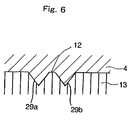
- the package side positioning groove portions may be formed into an inverted W-shape 12.
- This inverted W-shaped groove 12 having an inverted W-shape in cross section is formed by the groove defined between two projections 35a and 35b.
- the inverted W-shaped groove 12 and the V-groove 9 on the side of the optical element mounting substrate 2 are caused to face each other.
- the common positioning optical fiber 3 is inserted between the inverted W-shaped groove 12 and V-shaped groove 9 which face each other.
- the package 4 and the optical element mounting substrate 2 are positioned to each other.
- V-shaped grooves 29a and 29b for forming the inverted W-shaped groove 12 are formed closely in the mold 13 for molding the package. It is possible to readily form the V-shaped grooves 29a and 29b in the mold 13 with high precision as described above. For this reason, it is possible to form the inverted W-shaped groove 12 in the package 4 with high precision.
- the optical module 200 is constructed by using the package 4 in which the package side positioning groove portions are formed into the inverted W-shaped groove 12 as described above, it is possible to provide the same effect as in the above-described embodiment.
- the positioning optical fiber 3 is used as this positioning member.
- a molding pin made of ceramics or metal having a linear expansion coefficient of, for example, 1x10 -6 /K or less.
- the V-shaped grooves 9 are formed as the substrate side positioning groove portions in the optical element mounting substrate 2.
- the shape of the grooves is not limited thereto and may be selected as desired.
- arcuate grooves 5 are formed as the package side positioning groove portions in the package 4 in this embodiment, and the V-shaped grooves 9 are formed as the substrate side positioning groove portions in the optical element mounting substrate 2, each shape, size, number and position of formation of the package side positioning groove portions and the substrate side positioning groove portions are not limited to those of the above-described embodiment and may be selected suitably to position and fix the positioning members.
Landscapes
- Physics & Mathematics (AREA)
- General Physics & Mathematics (AREA)
- Optics & Photonics (AREA)
- Optical Couplings Of Light Guides (AREA)
- Led Device Packages (AREA)
Applications Claiming Priority (2)
| Application Number | Priority Date | Filing Date | Title |
|---|---|---|---|
| JP36666899 | 1999-12-24 | ||
| JP36666899 | 1999-12-24 |
Publications (3)
| Publication Number | Publication Date |
|---|---|
| EP1111421A2 true EP1111421A2 (fr) | 2001-06-27 |
| EP1111421A3 EP1111421A3 (fr) | 2004-05-06 |
| EP1111421B1 EP1111421B1 (fr) | 2006-05-31 |
Family
ID=18487356
Family Applications (1)
| Application Number | Title | Priority Date | Filing Date |
|---|---|---|---|
| EP00311594A Expired - Lifetime EP1111421B1 (fr) | 1999-12-24 | 2000-12-21 | Montage d'un module optique à puce retournée et alignement utilisant des rainures et des fibres optiques |
Country Status (3)
| Country | Link |
|---|---|
| US (2) | US20010033721A1 (fr) |
| EP (1) | EP1111421B1 (fr) |
| DE (1) | DE60028330T2 (fr) |
Families Citing this family (4)
| Publication number | Priority date | Publication date | Assignee | Title |
|---|---|---|---|---|
| US6883977B2 (en) * | 2000-12-14 | 2005-04-26 | Shipley Company, L.L.C. | Optical device package for flip-chip mounting |
| JP3584467B2 (ja) * | 2001-11-06 | 2004-11-04 | 船井電機株式会社 | 光ピックアップのハーフミラー固定装置 |
| CN111323878B (zh) * | 2020-04-01 | 2021-10-15 | 联合微电子中心有限责任公司 | 一种激光器芯片与硅基光电子芯片的耦合对准装置及方法 |
| JP2024023002A (ja) * | 2022-08-08 | 2024-02-21 | 住友電気工業株式会社 | 光モジュール及び光モジュールの製造方法 |
Family Cites Families (10)
| Publication number | Priority date | Publication date | Assignee | Title |
|---|---|---|---|---|
| US5412748A (en) * | 1992-12-04 | 1995-05-02 | Kabushiki Kaisha Toshiba | Optical semiconductor module |
| JPH07249798A (ja) * | 1994-03-09 | 1995-09-26 | Fujitsu Ltd | 光部品固定装置及びその製造方法 |
| JPH08248269A (ja) | 1995-03-08 | 1996-09-27 | Furukawa Electric Co Ltd:The | 光導波路部品 |
| JP3592406B2 (ja) * | 1995-07-10 | 2004-11-24 | 富士通株式会社 | 光モジュール及び光モジュールの製造方法 |
| JPH0980273A (ja) * | 1995-09-14 | 1997-03-28 | Fujitsu Ltd | 光学装置 |
| JPH09236729A (ja) * | 1996-02-29 | 1997-09-09 | Ricoh Co Ltd | 光モジュール |
| JP3274972B2 (ja) * | 1996-07-31 | 2002-04-15 | 京セラ株式会社 | 光学素子保持部材の製造方法 |
| JP3403306B2 (ja) * | 1997-01-17 | 2003-05-06 | 古河電気工業株式会社 | 光モジュール |
| JPH11344637A (ja) * | 1998-03-31 | 1999-12-14 | Ngk Insulators Ltd | 光ファイバ―アレイ |
| JP3684305B2 (ja) * | 1998-09-17 | 2005-08-17 | 日本オプネクスト株式会社 | 半導体レーザ結合装置および半導体受光装置 |
-
2000
- 2000-12-21 DE DE60028330T patent/DE60028330T2/de not_active Expired - Lifetime
- 2000-12-21 EP EP00311594A patent/EP1111421B1/fr not_active Expired - Lifetime
- 2000-12-22 US US09/746,733 patent/US20010033721A1/en not_active Abandoned
-
2003
- 2003-02-03 US US10/358,446 patent/US6715935B2/en not_active Expired - Fee Related
Also Published As
| Publication number | Publication date |
|---|---|
| US20010033721A1 (en) | 2001-10-25 |
| EP1111421A3 (fr) | 2004-05-06 |
| US20030142930A1 (en) | 2003-07-31 |
| DE60028330T2 (de) | 2007-05-10 |
| EP1111421B1 (fr) | 2006-05-31 |
| US6715935B2 (en) | 2004-04-06 |
| DE60028330D1 (de) | 2006-07-06 |
Similar Documents
| Publication | Publication Date | Title |
|---|---|---|
| EP0704732B1 (fr) | Couplage opto-électronique intégré et connecteur | |
| KR100195850B1 (ko) | 광모듈과 그 제조 공정 | |
| US8079125B2 (en) | Manufacturing method of multi-channel optical module | |
| US5790733A (en) | Optoelectronic device receptacle and method of making same | |
| US6459843B1 (en) | Optical connector assembly using partial large diameter alignment features | |
| US5940562A (en) | Stubless optoelectronic device receptacle | |
| US6270263B1 (en) | Optical module | |
| US7050678B1 (en) | Optical module, optical element attachment method, and receptacle-fitted optical module | |
| US20010019648A1 (en) | Ferrule assembly and optical module | |
| US5963693A (en) | Optical data link and method of manufacturing the same | |
| US6805493B2 (en) | Optical connector assembly using partial large diameter alignment features | |
| JP2001100062A (ja) | 光通信装置 | |
| EP1111421B1 (fr) | Montage d'un module optique à puce retournée et alignement utilisant des rainures et des fibres optiques | |
| EP0496331B1 (fr) | Moule pour la fabrication d'une module optique et procédé de fabrication utilisant ce moule | |
| US5275765A (en) | Method of manufacturing an optical module using a mold die | |
| JP2973542B2 (ja) | 光モジュール及びその製造装置及びその製造方法 | |
| JP2001242347A (ja) | 光モジュール | |
| JP4161899B2 (ja) | 光導波路モジュール | |
| JPH09222538A (ja) | 光部品 | |
| JP2864460B2 (ja) | 多心式光モジュール及びその製造方法 | |
| JP2973532B2 (ja) | 多心式光モジュール | |
| JP2000171669A (ja) | 光素子アレイモジュールおよびその製造方法ならびに多芯光コネクタと光素子搭載基板 | |
| KR20020021143A (ko) | 광 모듈 |
Legal Events
| Date | Code | Title | Description |
|---|---|---|---|
| PUAI | Public reference made under article 153(3) epc to a published international application that has entered the european phase |
Free format text: ORIGINAL CODE: 0009012 |
|
| 17P | Request for examination filed |
Effective date: 20010111 |
|
| AK | Designated contracting states |
Kind code of ref document: A2 Designated state(s): AT BE CH CY DE DK ES FI FR GB GR IE IT LI LU MC NL PT SE TR |
|
| AX | Request for extension of the european patent |
Free format text: AL;LT;LV;MK;RO;SI |
|
| PUAL | Search report despatched |
Free format text: ORIGINAL CODE: 0009013 |
|
| AK | Designated contracting states |
Kind code of ref document: A3 Designated state(s): AT BE CH CY DE DK ES FI FR GB GR IE IT LI LU MC NL PT SE TR |
|
| AX | Request for extension of the european patent |
Extension state: AL LT LV MK RO SI |
|
| 17Q | First examination report despatched |
Effective date: 20041206 |
|
| AKX | Designation fees paid |
Designated state(s): DE FR SE |
|
| GRAP | Despatch of communication of intention to grant a patent |
Free format text: ORIGINAL CODE: EPIDOSNIGR1 |
|
| GRAS | Grant fee paid |
Free format text: ORIGINAL CODE: EPIDOSNIGR3 |
|
| GRAA | (expected) grant |
Free format text: ORIGINAL CODE: 0009210 |
|
| RAP1 | Party data changed (applicant data changed or rights of an application transferred) |
Owner name: THE FURUKAWA ELECTRIC CO., LTD. |
|
| AK | Designated contracting states |
Kind code of ref document: B1 Designated state(s): DE FR SE |
|
| REF | Corresponds to: |
Ref document number: 60028330 Country of ref document: DE Date of ref document: 20060706 Kind code of ref document: P |
|
| PG25 | Lapsed in a contracting state [announced via postgrant information from national office to epo] |
Ref country code: SE Free format text: LAPSE BECAUSE OF FAILURE TO SUBMIT A TRANSLATION OF THE DESCRIPTION OR TO PAY THE FEE WITHIN THE PRESCRIBED TIME-LIMIT Effective date: 20060831 |
|
| ET | Fr: translation filed | ||
| PLBE | No opposition filed within time limit |
Free format text: ORIGINAL CODE: 0009261 |
|
| STAA | Information on the status of an ep patent application or granted ep patent |
Free format text: STATUS: NO OPPOSITION FILED WITHIN TIME LIMIT |
|
| 26N | No opposition filed |
Effective date: 20070301 |
|
| PGFP | Annual fee paid to national office [announced via postgrant information from national office to epo] |
Ref country code: DE Payment date: 20141216 Year of fee payment: 15 |
|
| PGFP | Annual fee paid to national office [announced via postgrant information from national office to epo] |
Ref country code: FR Payment date: 20141208 Year of fee payment: 15 |
|
| REG | Reference to a national code |
Ref country code: DE Ref legal event code: R119 Ref document number: 60028330 Country of ref document: DE |
|
| REG | Reference to a national code |
Ref country code: FR Ref legal event code: ST Effective date: 20160831 |
|
| PG25 | Lapsed in a contracting state [announced via postgrant information from national office to epo] |
Ref country code: DE Free format text: LAPSE BECAUSE OF NON-PAYMENT OF DUE FEES Effective date: 20160701 |
|
| PG25 | Lapsed in a contracting state [announced via postgrant information from national office to epo] |
Ref country code: FR Free format text: LAPSE BECAUSE OF NON-PAYMENT OF DUE FEES Effective date: 20151231 |