EP1111822A2 - Qualität-Anzeiger für drahtlosen Kanal - Google Patents
Qualität-Anzeiger für drahtlosen Kanal Download PDFInfo
- Publication number
- EP1111822A2 EP1111822A2 EP00311055A EP00311055A EP1111822A2 EP 1111822 A2 EP1111822 A2 EP 1111822A2 EP 00311055 A EP00311055 A EP 00311055A EP 00311055 A EP00311055 A EP 00311055A EP 1111822 A2 EP1111822 A2 EP 1111822A2
- Authority
- EP
- European Patent Office
- Prior art keywords
- signal
- incoming
- outgoing
- warning
- measure
- Prior art date
- Legal status (The legal status is an assumption and is not a legal conclusion. Google has not performed a legal analysis and makes no representation as to the accuracy of the status listed.)
- Withdrawn
Links
Images




Classifications
-
- H—ELECTRICITY
- H04—ELECTRIC COMMUNICATION TECHNIQUE
- H04B—TRANSMISSION
- H04B7/00—Radio transmission systems, i.e. using radiation field
- H04B7/02—Diversity systems; Multi-antenna system, i.e. transmission or reception using multiple antennas
- H04B7/12—Frequency diversity
-
- H—ELECTRICITY
- H04—ELECTRIC COMMUNICATION TECHNIQUE
- H04B—TRANSMISSION
- H04B7/00—Radio transmission systems, i.e. using radiation field
- H04B7/24—Radio transmission systems, i.e. using radiation field for communication between two or more posts
- H04B7/26—Radio transmission systems, i.e. using radiation field for communication between two or more posts at least one of which is mobile
-
- H—ELECTRICITY
- H04—ELECTRIC COMMUNICATION TECHNIQUE
- H04B—TRANSMISSION
- H04B17/00—Monitoring; Testing
- H04B17/30—Monitoring; Testing of propagation channels
- H04B17/309—Measuring or estimating channel quality parameters
- H04B17/318—Received signal strength
-
- H—ELECTRICITY
- H04—ELECTRIC COMMUNICATION TECHNIQUE
- H04M—TELEPHONIC COMMUNICATION
- H04M1/00—Substation equipment, e.g. for use by subscribers
- H04M1/72—Mobile telephones; Cordless telephones, i.e. devices for establishing wireless links to base stations without route selection
- H04M1/724—User interfaces specially adapted for cordless or mobile telephones
-
- H—ELECTRICITY
- H04—ELECTRIC COMMUNICATION TECHNIQUE
- H04B—TRANSMISSION
- H04B7/00—Radio transmission systems, i.e. using radiation field
- H04B7/02—Diversity systems; Multi-antenna system, i.e. transmission or reception using multiple antennas
- H04B7/04—Diversity systems; Multi-antenna system, i.e. transmission or reception using multiple antennas using two or more spaced independent antennas
- H04B7/06—Diversity systems; Multi-antenna system, i.e. transmission or reception using multiple antennas using two or more spaced independent antennas at the transmitting station
-
- H—ELECTRICITY
- H04—ELECTRIC COMMUNICATION TECHNIQUE
- H04B—TRANSMISSION
- H04B7/00—Radio transmission systems, i.e. using radiation field
- H04B7/02—Diversity systems; Multi-antenna system, i.e. transmission or reception using multiple antennas
- H04B7/04—Diversity systems; Multi-antenna system, i.e. transmission or reception using multiple antennas using two or more spaced independent antennas
- H04B7/08—Diversity systems; Multi-antenna system, i.e. transmission or reception using multiple antennas using two or more spaced independent antennas at the receiving station
- H04B7/0837—Diversity systems; Multi-antenna system, i.e. transmission or reception using multiple antennas using two or more spaced independent antennas at the receiving station using pre-detection combining
-
- H—ELECTRICITY
- H04—ELECTRIC COMMUNICATION TECHNIQUE
- H04B—TRANSMISSION
- H04B7/00—Radio transmission systems, i.e. using radiation field
- H04B7/02—Diversity systems; Multi-antenna system, i.e. transmission or reception using multiple antennas
- H04B7/10—Polarisation diversity; Directional diversity
Definitions
- the present invention relates to wireless telecommunications in general and, in particular, to a method and apparatus that provide an indication of the quality of a wireless channel.
- Fig. 1 depicts a schematic diagram of a portion of a wireless telecommunications system, designated generally as 100 , that services a number of wireless terminals that are situated within a geographic region.
- Wireless telecommunications system 100 typically comprises wireless switching center 101 and base stations 111 to 113 .
- Wireless switching center 101 is responsible for, among other things, routing calls between wireless terminals or, alternatively, between a wireless terminal and a wireline terminal that is accessible to wireless telecommunications system 100 via public switched telephone network 103 .
- the geographic region serviced by wireless switching center 101 is typically partitioned into a number of spatially distinct regions called "cells.” As depicted in Fig. 1, each cell is schematically represented by a hexagon; in practice, however, each cell invariably has an irregular shape that depends on the topography of the terrain and other factors.
- each cell contains a base station that is responsible for providing network access for the wireless terminals within that cell.
- Each base station typically includes the antennas and radios for communicating with the wireless terminals within the cell, and also includes the transmission equipment needed for communicating with wireless switching center 101 .
- a base station typically establishes a duplex communication channel with a wireless terminal for the transmission of user information (e.g ., voice, data, video, multimedia).
- the base station and wireless terminal can also establish one or more simplex or duplex communications channels for exchanging signaling information.
- a duplex channel carries user or signaling information, it can be conceptualized as two separate and distinct simplex channels that operate in opposite directions.
- a simplex channel transmitted by a base station and received by a wireless terminal is known as a "downlink" or, alternatively, as a "forward channel.”
- An example downlink channel is designated as 105 in Fig, 1.
- a simplex channel transmitted by a wireless terminal and received by a base station is known as an "uplink” or, alternatively, as a "reverse channel.”
- An example uplink channel is designated as 106 in Fig. 1.
- both an uplink signal as received by a base station and a downlink signal as received by a wireless terminals are “incoming signals.”
- both a downlink signal transmitted by a base station and an uplink signal as transmitted by a wireless terminal are "outgoing signals.”
- one embodiment comprises a method of processing an outgoing signal by receiving an incoming signal, generating a measure of signal strength of the incoming signal, and adding an outgoing warning signal to said outgoing signal when, based on at least said measure of signal strength, said incoming signal is of unsatisfactory quality.
- FIG. 1 is a schematic diagram of a wireless telecommunications system.
- FIG. 2 is a block diagram of a base station according to one embodiment of the present invention.
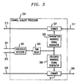
- FIG. 3 is a block diagram of an illustrative channel quality processor as shown in Fig. 2.
- FIG. 4 is a block diagram of a wireless terminal according to one embodiment of the present invention.
- FIG. 5 is a block diagram of a base station according to a second embodiment of the present invention.
- a base station typically comprises more sophisticated radio equipment than a wireless terminal comprises and is, therefore, typically capable of transmitting with greater power and receiving with greater clarity than a wireless terminal. This disparity can cause the incoming signal received by a wireless terminal to have a different quality than the incoming signal received by a base station.
- the lack of a good quality received signal will alert the recipient of the uplink signal to the fact that he cannot hear the user of the wireless terminal (i.e., the uplink is not functioning).
- the recipient of the uplink signal will, however, be incapable of discerning whether he can still be heard (i.e., whether the downlink is functioning).
- the semantic discontinuities may alert the respective parties to the fact that there is a problem. This condition is generally less common.
- the automated system may respond in a manner that is unexpected, which might lead the user to incorrectly conclude that it is the automated system that is inoperable, and not the telecommunications link.
- Some embodiments of the present invention are advantageously capable of determining that either the uplink or the downlink signal is not received with sufficient quality, and of notifying one or both parties of that fact.
- Fig. 2 depicts a block diagram of one embodiment of the present invention, base station 113a, which receives an outgoing signal from wireless switching center 101 and transmits it as downlink signal 105 to wireless terminal 150 , and which also receives uplink signal 106 , which is the incoming signal, from wireless terminal 150 and transmits it to wireless switching center 101 .
- Base station 113a advantageously comprises: receive antenna 220 , front-end 200 , demodulator 202 , decoder 204 , channel quality processor 224 , translator 208 , encoder 214 , modulator 216 , transmitter 218 and transmit antenna 222 , interconnected as shown.
- the incoming signal is received by receive antenna 220 and processed by front-end 200 , which prepares the incoming signal for demodulation by demodulator 202 , in well-known fashion.
- Front-end 200 advantageously also measures the signal strength of the incoming signal, in well-known fashion, and sends the resulting measure to channel quality processor 224 , via lead 201 .
- Front-end 200 can measure the signal strength of the incoming signal according to any of one or more criteria (e.g., signal-to-noise ratio, absolute power in dBm, etc.). It will be clear to those skilled in the art how to make and use front-end 200 and demodulator 204 .
- the incoming signal from front-end 200 is provided to demodulator 202 , which demodulates the incoming signal according to the appropriate demodulation scheme, in well-known fashion.
- the incoming signal from demodulator 202 is provided to decoder 204 , which decodes the incoming signal and advantageously determines a measure of the error rate in the incoming signal, in well-known fashion. For example, when base station 113a is Interim Standard 95 ("IS-95”) compliant, the error rate could be based on the frame error rate (“FER”) of the signal.
- Decoder 204 advantageously provides both the decoded incoming signal and the measure of error rate to channel quality processor 224 .
- Channel quality processor 224 advantageously receives the measure of signal strength from front end 200 , the measure of error rate from decoder 204 , the incoming signal from decoder 204 and the outgoing signal from wireless switching center 101 , and outputs, an occasionally modified, outgoing signal to encoder 214 and outputs an, occasionally modified, incoming signal to wireless switching center 101 .
- the details of channel quality processor 224 will be described below with respect to Fig. 3.
- the outgoing signal passes from channel quality processor 224 through encoder 214 , modulator 216 and transmitter 218 , in well-known fashion, on its way to wireless terminal 150 .
- Channel quality processor 224 advantageously receives both the measure of the signal strength and the measure of the error rate in the incoming signal and uses one or both criteria to determine when the quality of the incoming signal is above or below some acceptable threshold. For example, channel quality processor 224 could determine that the incoming signal quality is unsatisfactory when either: (1) the signal strength is below a predetermined threshold, or (2) the error rate is above another threshold. Alternatively, channel quality processor 224 could determine that the incoming signal quality is unsatisfactory when, and only when, both: (1) the signal strength is below a predetermined threshold, and (2) the error rate is above another threshold.
- channel quality processor 224 determines that the incoming signal quality is unsatisfactory, it adds an "outgoing warning signal" to the outgoing signal and, advantageously, also adds an "incoming warning signal” to the incoming signal.
- the outgoing warning signal is an in-band signal ( i . e ., it is within the same logical communications channel as the outgoing signal) and in other embodiments of the present invention, the outgoing warning signal is an out-of-band signal ( i.e., it is not within the same logical communications channel as the outgoing signal).
- the incoming warning signal is an in-band signal ( i.e ., it is within the same logical communications channel as the incoming signal) and in other embodiments of the present invention, the incoming warning signal is an out-of-band signal ( i.e., it is not within the same logical communications channel as the incoming signal).
- either or both of the incoming signal and outgoing signal represent audio signals
- either or both of the outgoing warning signal and the incoming warning signal could represent, for example, an audible tone that will be heard by the respective party.
- either or both of the outgoing warning signal and the incoming warning signal could be encoded messages that directs the respective party's terminal to create a visible, audible or tactile indication that the incoming signal is not being received. It is preferred that the outgoing warning signal and the incoming warning signal be different so that each respective user can discern the exact nature of the problem.
- both base station 113 and wireless terminal 150 could have the functionality provided by channel quality processor 224 .
- both parties could always be apprised of both the existence of a problem and of the nature of the problem.
- channel quality processor 224 may include a time delay (e.g. a hysteresis circuit) that would delay the addition of either or both of the incoming warning signal or the outgoing warning signal unless the incoming signal's quality was consistently unsatisfactory for a predetermined length of time (e.g ., at least 200 ms.), but would immediately cease adding either or both of the incoming warning signal or the outgoing warning signal when said incoming signal becomes satisfactory again.
- a time delay e.g. a hysteresis circuit
- Channel quality processor 224 advantageously comprises: threshold detector 301 , time delay 303, outgoing warning signal generator 305, summer 307 incoming warning signal 309 and summer 311.
- Threshold detector 301 advantageously receives both the measure of signal strength on lead 201 and the measure of error rate on lead 203 and determines the quality of the incoming signal and outputs a binary signal to time delay 303 , which binary signal indicates when the quality of the incoming signal is unsatisfactory.
- threshold detector 301 indicates to time delay 303 that the quality of the incoming signal is unsatisfactory
- time delay 303 waits, for the reasons discussed above, to assert its output until its input has been consistently asserted for a predetermined period of time.
- time delay 303 When the input to time delay 303 has been consistently asserted for a predetermined period of time, time delay 303 asserts its output, which directs outgoing warning signal generator 305 and incoming warning signal generator 309 to generate their respective signals.
- the output of outgoing warning signal generator 305 is fed into summer 307 where it is summed, in well-known fashion, with the unencoded outgoing signal on lead 211
- the output of incoming warning signal generator 309 is fed into summer 311 where it is summed, also in well-known fashion, with the decoded incoming signal on lead 205 .
- Fig. 4 depicts a block diagram of an embodiment of the present invention, which comprises a wireless terminal.
- This embodiment operates analogously to the embodiment presented above, which comprised a base station, but in this embodiment uplink signal 106 is the outgoing signal and downlink signal 105 is the incoming signal.
- the illustrative wireless terminal can comprise indicator 403, which can output a visible, audible and/or tactile indication to the user of the wireless terminal that the incoming and/or outgoing signal is not being received with sufficient quality.
- Fig. 5 depicts a block diagram of another embodiment of the present invention, base station 113b , which has multiple reception paths for diversity reception.
- Base station 113b advantageously comprises: receive antennas 511 and 521 , front ends 513 and 523 , demodulators 515 and 525 , decoders 517 and 527 , diversity processor 519 , channel quality processor 509 , encoder 507 , modulator 505 and transmitter 503 , interconnected as shown.
- Uplink signal 106 the incoming signal, is received by receive antennas 511 and 521 and processed by front ends 513 and 523 , respectively, in preparation for demodulation by demodulators 515 and 525 , respectively.
- Both front ends 513 and 523 advantageously measure the signal strength of their respectively received incoming signal and send the resulting measure to channel quality processor 509. It should be understood that although both front end 513 and front end 523 are seeking to receive the same signal, because of the diversity of antennas 511 and 521 , the quality of the signal actually received by front end 513 is usually different from the quality of the signal received by front end 523 .
- Front end 513 sends its measure of signal strength to channel quality processor 509 on lead 514 and front end 523 sends its measure on lead 524 .
- the signal from front end 513 is provided to demodulator 515 , which demodulates the signal according to the appropriate demodulation scheme, in well-known fashion.
- the demodulated signal from demodulator 515 is provided to decoder 517 , which decodes the signal and advantageously determines a measure of the error rate in the incoming signal, in well-known fashion.
- Decoder 515 advantageously provides the decoded incoming signal to diversity processor 519 and the measure of error rate to channel quality processor 509 .
- the operation of demodulator 525 and decoder 527 is analogous to that of demodulator 515 and decoder 517 .
- Diversity processor 519 combines the signals from decoder 517 and decoder 527 , in well-known fashion, to minimize the effects of fading and produces an output signal that is, probabilistically, more robust than either signal alone.
- the output of diversity processor 519 is provided to channel quality processor 509 .
- Channel quality processor 509 advantageously receives the measures of signal strength from front end 513 and front end 523 , the measures of error rate from decoder 517 and decoder 527 , the decoded incoming signal from diversity processor 519 and the unencoded outgoing signal from wireless switching center 101 , and outputs a potentially modified outgoing signal to encoder 507 and a potentially modified incoming signal to wireless switching center 101 .
- the outgoing signal passes from channel quality processor 509 through encoder 507 , modulator 505 and transmitter 503 , in well-known fashion, on its way to wireless terminal 150 .
- Channel quality processor 509 advantageously receives both measures of the signal strength and both measures of the error rate and advantageously uses all four measures to determine when the quality of the incoming signal is above or below some acceptable threshold. Otherwise, the design and operation of channel quality processor 509 is analogous to channel quality processor 224 , except that it has four measures of signal quality on which to make its. determination. From the above description, it will be clear to those skilled in the art how to make and use channel quality processor 509.
- the base station e.g., the channel quality processor
- the channel quality processor may be moved from being located in the base station into one or more servers that are remote from the base station.
- embodiments of the present invention can be embodied in peer-to-peer telecommunications equipment, such as walkie-talkies, CB radios and the like.
Landscapes
- Engineering & Computer Science (AREA)
- Computer Networks & Wireless Communication (AREA)
- Signal Processing (AREA)
- Quality & Reliability (AREA)
- Physics & Mathematics (AREA)
- Electromagnetism (AREA)
- Human Computer Interaction (AREA)
- Mobile Radio Communication Systems (AREA)
- Monitoring And Testing Of Transmission In General (AREA)
Applications Claiming Priority (2)
| Application Number | Priority Date | Filing Date | Title |
|---|---|---|---|
| US47129299A | 1999-12-24 | 1999-12-24 | |
| US471292 | 1999-12-24 |
Publications (2)
| Publication Number | Publication Date |
|---|---|
| EP1111822A2 true EP1111822A2 (de) | 2001-06-27 |
| EP1111822A3 EP1111822A3 (de) | 2003-10-22 |
Family
ID=23871038
Family Applications (1)
| Application Number | Title | Priority Date | Filing Date |
|---|---|---|---|
| EP00311055A Withdrawn EP1111822A3 (de) | 1999-12-24 | 2000-12-12 | Qualität-Anzeiger für drahtlosen Kanal |
Country Status (3)
| Country | Link |
|---|---|
| EP (1) | EP1111822A3 (de) |
| JP (1) | JP2001218248A (de) |
| KR (1) | KR20010062635A (de) |
Cited By (7)
| Publication number | Priority date | Publication date | Assignee | Title |
|---|---|---|---|---|
| EP1686779A1 (de) * | 2005-01-26 | 2006-08-02 | Brother Kogyo Kabushiki Kaisha | Schurlos-Telefone-Gerätesatz |
| EP1956790A1 (de) * | 2007-02-06 | 2008-08-13 | Research In Motion Limited | Tragbare elektronische Vorrichtung mit Voice-over-IP-Qualitätsanzeige und dazugehöriges Verfahren |
| US7668088B2 (en) | 2007-02-06 | 2010-02-23 | Research In Motion Limited | Handheld electronic device including voice over IP quality indicator, and associated method |
| GB2463303A (en) * | 2008-09-09 | 2010-03-10 | Avaya Inc | Local indication of far-end received signal quality |
| CN1778082B (zh) * | 2003-02-19 | 2010-04-28 | 高通股份有限公司 | 在多用户通信系统中的受控叠加编码 |
| CN101801078A (zh) * | 2003-02-19 | 2010-08-11 | 高通股份有限公司 | 在多用户通信系统中的受控叠加编码 |
| US9680905B2 (en) | 2013-12-23 | 2017-06-13 | David Arthur Yost | System for intelligible audio conversation over unreliable digital transmission media |
Family Cites Families (8)
| Publication number | Priority date | Publication date | Assignee | Title |
|---|---|---|---|---|
| US4675656A (en) * | 1984-03-16 | 1987-06-23 | Narcisse Bernadine O | Out-of-range personnel monitor and alarm |
| US5471650A (en) * | 1993-01-07 | 1995-11-28 | Northern Telecom Limited | Radio link parameter control in wireless personal communications system |
| US5469471A (en) * | 1994-02-01 | 1995-11-21 | Qualcomm Incorporated | Method and apparatus for providing a communication link quality indication |
| US5809414A (en) * | 1995-11-22 | 1998-09-15 | Northern Telecom Limited | User out-of-range indication for digital wireless systems |
| JP3631601B2 (ja) * | 1996-11-27 | 2005-03-23 | 株式会社日立製作所 | 移動通信システム送信電力制御方法及びその実施装置 |
| KR100290668B1 (ko) * | 1997-10-13 | 2001-07-12 | 윤종용 | 부호분할다중접속통신시스템의순방향링크의전력제어방법 |
| JPH11262066A (ja) * | 1998-03-12 | 1999-09-24 | Sony Corp | 携帯通信端末 |
| KR100367079B1 (ko) * | 2000-11-15 | 2003-01-09 | 주식회사 트라넷 | 이동통신용 중계기의 오류 검출 시스템 및 그 방법 |
-
2000
- 2000-12-12 EP EP00311055A patent/EP1111822A3/de not_active Withdrawn
- 2000-12-22 JP JP2000389860A patent/JP2001218248A/ja active Pending
- 2000-12-22 KR KR1020000080384A patent/KR20010062635A/ko not_active Ceased
Cited By (12)
| Publication number | Priority date | Publication date | Assignee | Title |
|---|---|---|---|---|
| CN1778082B (zh) * | 2003-02-19 | 2010-04-28 | 高通股份有限公司 | 在多用户通信系统中的受控叠加编码 |
| CN101801078A (zh) * | 2003-02-19 | 2010-08-11 | 高通股份有限公司 | 在多用户通信系统中的受控叠加编码 |
| CN101801078B (zh) * | 2003-02-19 | 2013-10-09 | 高通股份有限公司 | 在多用户通信系统中的受控叠加编码 |
| EP1686779A1 (de) * | 2005-01-26 | 2006-08-02 | Brother Kogyo Kabushiki Kaisha | Schurlos-Telefone-Gerätesatz |
| EP1956790A1 (de) * | 2007-02-06 | 2008-08-13 | Research In Motion Limited | Tragbare elektronische Vorrichtung mit Voice-over-IP-Qualitätsanzeige und dazugehöriges Verfahren |
| US7668088B2 (en) | 2007-02-06 | 2010-02-23 | Research In Motion Limited | Handheld electronic device including voice over IP quality indicator, and associated method |
| US8537668B2 (en) | 2007-02-06 | 2013-09-17 | Blackberry Limited | Handheld electronic device including voice over IP quality indicator, and associated method |
| GB2463303A (en) * | 2008-09-09 | 2010-03-10 | Avaya Inc | Local indication of far-end received signal quality |
| GB2463303B (en) * | 2008-09-09 | 2013-06-12 | Avaya Inc | Sharing of electromagnetic-signal measurements for providing feedback and transmit-path signal quality |
| US8483679B2 (en) | 2008-09-09 | 2013-07-09 | Avaya Inc. | Sharing of electromagnetic-signal measurements for providing feedback about transmit-path signal quality |
| US9326160B2 (en) | 2008-09-09 | 2016-04-26 | Avaya Inc. | Sharing electromagnetic-signal measurements for providing feedback about transmit-path signal quality |
| US9680905B2 (en) | 2013-12-23 | 2017-06-13 | David Arthur Yost | System for intelligible audio conversation over unreliable digital transmission media |
Also Published As
| Publication number | Publication date |
|---|---|
| EP1111822A3 (de) | 2003-10-22 |
| KR20010062635A (ko) | 2001-07-07 |
| JP2001218248A (ja) | 2001-08-10 |
Similar Documents
| Publication | Publication Date | Title |
|---|---|---|
| JP2583489B2 (ja) | 無線伝送方式 | |
| US6381472B1 (en) | TDD/TTY-digital access | |
| BG62346B1 (bg) | Метод и система за сигнализиране на селективно повикване скомбинирано персонално повикване с широк обхват на действие ивисокоскоростно предаване на данни чрез радиотелефонниприемопредавателни станции | |
| US20070274514A1 (en) | Method and apparatus for acoustic echo cancellation in a communication system providing TTY/TDD service | |
| JP2001500693A (ja) | 無線通信チャンネル用会議発呼システム及び方法 | |
| KR100827944B1 (ko) | 제어 채널 상에서의 간섭의 영향을 감소시키기 위한 방법 및 장치 | |
| EP1111822A2 (de) | Qualität-Anzeiger für drahtlosen Kanal | |
| US20010011216A1 (en) | Digital cordless phone system for improving distance of speech communication using error concealment and method thereof | |
| US6631274B1 (en) | Mechanism for better utilization of traffic channel capacity in GSM system | |
| US5710772A (en) | TDMA radio communication system | |
| CN111314867A (zh) | Dmr系统的语音传输、接收方法及装置、存储介质、终端 | |
| US6999798B2 (en) | System and method for making notification of reception limitation status of mobile telephone | |
| US20140362760A1 (en) | Method and apparatus for providing multi-rate broadcast services | |
| JPH0661903A (ja) | 通話装置 | |
| US20020042286A1 (en) | Portable cellular phone system with automatic answering telephone function | |
| JPS6243230A (ja) | コ−ドレス電話器 | |
| JPH08130501A (ja) | 移動通信システム | |
| JPS6052132A (ja) | 移動局におけるダイバ−シチ受信方式 | |
| US20040192367A1 (en) | Dispatch call "cut-in" alert | |
| EP1086569A1 (de) | Sprachnachrichtensystem | |
| US20110256892A1 (en) | Method, apparatus and system for transmitting signal | |
| JP5955755B2 (ja) | デジタル無線通信システムおよび無線装置 | |
| US20090209226A1 (en) | Communication device, communication control method, and recording medium | |
| JPH09331580A (ja) | メッセージ伝送サービス機能を備えた無線通信システム | |
| JPH11298420A (ja) | Wllシステムにおける信号伝送方式 |
Legal Events
| Date | Code | Title | Description |
|---|---|---|---|
| PUAI | Public reference made under article 153(3) epc to a published international application that has entered the european phase |
Free format text: ORIGINAL CODE: 0009012 |
|
| AK | Designated contracting states |
Kind code of ref document: A2 Designated state(s): AT BE CH CY DE DK ES FI FR GB GR IE IT LI LU MC NL PT SE TR |
|
| AX | Request for extension of the european patent |
Free format text: AL;LT;LV;MK;RO;SI |
|
| PUAL | Search report despatched |
Free format text: ORIGINAL CODE: 0009013 |
|
| AK | Designated contracting states |
Kind code of ref document: A3 Designated state(s): AT BE CH CY DE DK ES FI FR GB GR IE IT LI LU MC NL PT SE TR |
|
| AX | Request for extension of the european patent |
Extension state: AL LT LV MK RO SI |
|
| RIC1 | Information provided on ipc code assigned before grant |
Ipc: 7H 04Q 7/22 B Ipc: 7H 04M 1/725 B Ipc: 7H 04Q 7/38 B Ipc: 7H 04B 7/12 B Ipc: 7H 04B 17/00 A |
|
| 17P | Request for examination filed |
Effective date: 20040413 |
|
| AKX | Designation fees paid |
Designated state(s): DE FR GB |
|
| STAA | Information on the status of an ep patent application or granted ep patent |
Free format text: STATUS: THE APPLICATION HAS BEEN WITHDRAWN |
|
| 18W | Application withdrawn |
Effective date: 20051107 |