EP1112603B1 - Abstimmbarer hohlraumresonator - Google Patents
Abstimmbarer hohlraumresonator Download PDFInfo
- Publication number
- EP1112603B1 EP1112603B1 EP99944392A EP99944392A EP1112603B1 EP 1112603 B1 EP1112603 B1 EP 1112603B1 EP 99944392 A EP99944392 A EP 99944392A EP 99944392 A EP99944392 A EP 99944392A EP 1112603 B1 EP1112603 B1 EP 1112603B1
- Authority
- EP
- European Patent Office
- Prior art keywords
- cavity resonator
- adjustment device
- resonator
- tunable
- spring
- Prior art date
- Legal status (The legal status is an assumption and is not a legal conclusion. Google has not performed a legal analysis and makes no representation as to the accuracy of the status listed.)
- Expired - Lifetime
Links
Images

Classifications
-
- H—ELECTRICITY
- H01—ELECTRIC ELEMENTS
- H01P—WAVEGUIDES; RESONATORS, LINES, OR OTHER DEVICES OF THE WAVEGUIDE TYPE
- H01P7/00—Resonators of the waveguide type
- H01P7/06—Cavity resonators
Definitions
- the invention relates to a tunable cavity resonator according to the preamble of claim 1. Further relates the invention a tunable microwave oscillator, who uses such a cavity resonator.
- Tunable cavity resonators come i.a. in microwave oscillators used for generating carrier signals used in microwave communication become.
- Such oscillators essentially exist from a microwave amplifier operated in feedback is, and a cavity resonator of high quality, the is in the feedback branch of the oscillator and filter the phase noise generated in the amplifier.
- a microwave oscillator uses a mechanical or electrical phase shifter for adjusting the phase condition in the feedback branch and a high frequency coupler for coupling out the Useful signal (carrier signal).
- the setting of the oscillator frequency takes place in two stages: For coarse adjustment, first the resonance frequency the tunable cavity resonator in suitable Way changed. This is done by means of the adjusting device, by which the position of the Abstimmulation opposite the Resonator emotions is adjusted. For fine adjustment of Oscillator frequency is then using the phase shifter by adjusting the phase in the feedback branch of the Oscillator the oscillator frequency within the resonance width of the tuned cavity resonant targeted postponed.
- a difficulty in such a two-stage tuning of an oscillator results from the fact that the achievable by the phase adjustment maximum frequency deviation is relatively small and at Resonatorgüten above 10 4 (ie, Q> 10 4 ), for example, only about 100 kHz.
- complete tunability of the microwave oscillator can only be achieved if the minimum frequency change ⁇ R (min) achievable in the resonant frequency tuning (ie the tuning of the cavity resonator) is less than the maximum frequency swing mentioned with variation of the phase in the feedback branch of the oscillator.
- cavity resonators are required with an extremely high tuning accuracy.
- the invention is based on the object, a cavity resonator to create a high setting accuracy with respect to its resonant frequency.
- a cavity resonator is to be provided which has a high quality and yet when used in a Microwave oscillator full tunability the same allows.
- the invention aims at it from, a fully tunable microwave oscillator to provide a cavity resonator high quality.
- the first spring element is formed from at least one plate spring and the second spring element of a circumferentially fixed, from the plate spring centrally acted diaphragm is realized.
- Such a spring mechanism leaves to be rigid enough to withstand external shocks or vibration insensitive. Furthermore, suitable plate and plate springs with the required high spring constant easily manufactured become.
- the adjusting device preferably consists of a particular manually operable mechanical actuator and a mechanical actuator downstream of the first electromechanical actuator, in particular first piezoelectric element.
- the first electromechanical actuator allows an electrical control of the adjusting device, which is particularly advantageous if the adjusting device is operated in a control loop operation for adjusting the resonance frequency ⁇ R.
- the electromechanical actuator can also be used, for example, to compensate for temperature-induced drifts and, moreover, make operation of the mechanical actuator superfluous in a limited stroke range.
- the tuning disk is made of a dielectric material, in particular sapphire.
- a tuning plate has very low dielectric losses especially at low temperatures, resulting in a high Q ⁇ 10 7 of the cavity resonator (defined as the product of the resonance frequency ⁇ R of the quotient of the data stored in the resonator field energy and in the resonator can be achieved power dissipation).
- variable position Shims also around a wall element (For example, ceiling wall) of the cavity resonator act.
- a wall element for example, ceiling wall
- the dielectric body is arranged in the resonator body.
- a dielectric body is provided, and that the tuning disk within the resonator body at a small distance d to a flat surface the dielectric body is arranged.
- a Construction is a major part of the field energy in the stored dielectric body, wherein by means of a Position change of the tuning disc a sensitive change reach the resonant frequency of the cavity resonator is.
- the dielectric body When using a dielectric body is a Another structurally advantageous realization variant in it, the dielectric body on one by means of a second electromechanical actuator, in particular second piezoelectric element in its height variable lifting floor to install. This way can be done without big Effort a desired Nominal- or output distance between the tuning plate and the flat surface of the dictate the dielectric body, which then through the Control device according to the invention with downstream Translation mechanism in a suitable manner fine-adjusted becomes.
- Fig. 1 shows a cavity resonator 1 in Zylinderbäuweise with a resonant frequency ⁇ R in the GHz range.
- the cavity resonator 1 has a circular disk-shaped bottom plate 2, a cylindrical peripheral wall 3 and a top wall 4.
- the resonator wall elements 2, 3 and 4 are made of a metal of good electrical conductivity such as Cu or a HTSC material and define a cavity 5 in its interior.
- the bottom plate 2 has distributed over its circumference Through holes 6, which of threaded screws. 7 are passed, by means of which the bottom plate 2 at a bottom-side flange 8 of the peripheral wall 3 fixed is. Between the bottom plate 2 and the flange 8 is an annular disk-shaped spacer 9 predetermined Strength and above a circular disc-shaped lifting bottom 10 arranged.
- the multi-layer piezoelectric element 11 has a maximum stroke of a few microns, which transmitted to the lifting floor 10 can be and a central bulge of the same causes.
- the dielectric cylinder 30 consists of a dielectric material with a high Dielectric constant ⁇ (for example, sapphire) and is coaxial with the peripheral wall 3 of the cavity resonator 1 arranged.
- the input and output antennas 13a, 13b are each formed as a coaxial cable with end Coaxial grinding executed.
- the top wall 4 of the cavity 1 is by means of a annular disc-shaped spacer 14 preset Strength of a ceiling-side flange 15 of the peripheral wall 3 spaced and in a similar manner as the bottom wall 2 through through holes 16 passing through threaded screws 17 fixed to the ceiling-side flange 15.
- a formed in the form of a thin, metallic disc Plate spring 18 is at the edge between the annular disk-shaped spacer element 14 and the ceiling wall 4 fixed.
- the plate spring 18 limited in her central area an existing in the ceiling wall 4, cylindrical spring receiving space 19.
- the spring receiving space 19 contains three in the example shown here superimposed disc springs 20 which surround a central Guide element 21 stored around and bottom side are supported on the plate spring 18.
- a micrometer screw 22 which consists of a fixed to the ceiling wall 4 Screw 21 and one in one Fine thread guided rotary member 24 consists.
- the rotary member 24 loaded with a bottom-side projecting adjusting pin 24a the upper end of one in a central hole of the screw 23 guided punch 25, the lower End of acting on the upper plate spring 20 first Multilayer piezoelectric element 26 acted upon.
- the movement path is transmitted to the first multi-layer piezoelectric element 26 and can additionally be changed, ie shortened or extended, by the latter.
- the output side of the first multi-layer piezoelectric element 26 occurring linear stroke .DELTA.x 1 acts on the uppermost plate spring 20 and compresses them.
- the plate springs 20 press on the plate spring 18 and deflect it in its central region by a deflection .DELTA.x 2 . Due to the opposing force exerted by the plate spring 18, the output-side deflection path ⁇ x 2 is smaller than the input-side linear displacement ⁇ x 1 .
- the reduction of the deflection path .DELTA.x 2 with respect to .DELTA.x 1 is determined by the spring constant k 1 of the disc spring stack and the spring constant k 2 of the plate spring 18.
- a tuning plate 28 is attached via a stem 27.
- the Abstimmsay 28 extends parallel and at a small distance d to a flat surface 29 of the dielectric cylinder 30.
- the tuning plate 28 also displaced by .DELTA.x 2 , so that a previously set Distance d between the tuning disk 28 and the cylindrical body 30 is shortened to d- ⁇ x 2 .
- Fig. 2 shows in the form of a block diagram of the principal Structure of a microwave oscillator, the in Fig. 1 shown cavity resonator 1 used.
- Amplifier signal 41 of an amplifier 40 becomes a high frequency coupler 42 supplied.
- the high frequency coupler 42 coupled from the amplifier signal 41, on the one hand, a useful signal 43 and passes the amplifier signal 41 on the other hand to the cavity resonator 1 on.
- the coupling of the amplifier signal 41 in the cavity 1 takes place via the input antenna 13a.
- an output signal 44th decoupled from the cavity 1 and an electrical or mechanically actuated phase shifter 45 is supplied, which for adjusting the phase condition in the feedback branch 41, 42, 1, 44, 45 is provided.
- the phase-shifted generated by the phase shifter 45 Feedback signal 46 is fed to the amplifier 40.
- the microwave oscillator can only be continuously tuned when the cavity resonator 1 reaches a required setting accuracy of the resonance frequency ⁇ R of about 100 kHz or less. It is unfavorable that the tuning slope ⁇ R / ⁇ x 2 of a cavity resonator increases proportionally with its quality Q. In the case of resonators 1 with comparatively low quality (Q ⁇ 10 4 ), a typical tuning slope of 10 kHz / ⁇ m is observed. This means that the setting accuracy of the tuning mechanism with respect to the achievable positional accuracy of the tuning plate 28 must be only about 10 microns in order to achieve the required tuning accuracy ⁇ R of the resonant frequency of 100 kHz.
- the tuning slope is at a quality of Q ⁇ 10 7 already 10 3 kHz / micron.
- a quality of Q ⁇ 10 7 can be achieved with the cavity resonator 1 according to the invention by cooling it to approximately 77K, because in this way the so-called whispering gallery modes can significantly reduce the dielectric losses occurring in the dielectric cylinder 30.
- the tuning mechanism of the cavity 1 In order to achieve continuous tunability of a microwave oscillator with the cooled cavity 1, the tuning mechanism of the cavity 1 must then have a setting accuracy of 0.1 ⁇ m.
- the translation mechanism 18, 20 shown in FIG. 1 allows (when using a micrometer screw 22 a setting accuracy of 50 microns per revolution) such a setting accuracy and thus allows the realization of a fully tunable microwave oscillator with a cavity resonator 1 Q ⁇ 10 7 .
- the high setting accuracy of the tuning mechanism 22, 20, 18 is based in addition to the reduction of the invention Movement path through the translation mechanism 18, 20 also because of the construction of the translation mechanism 18, 20 of successively connected spring elements in this virtually no movement occurs. Thereby also a high reproducibility of the Setting position allows.
- the first and second multilayer piezoelectric elements 26, 11 can also be used for electrical adjustment of the resonant frequency ⁇ R.
- the first multilayer piezoelectric element 26 causes a movement of the tuning disk 28 relative to the stationary dielectric cylinder 30, while an operation of the second multilayer piezoelectric element 11 results in a movement of the dielectric cylinder 30 relative to the stationary tuning disk 28.
- the first multi-layer piezoelectric element 26 connected upstream of the transmission mechanism 18, 20 makes possible a very precise electrical fine adjustment of the resonance frequency ⁇ R and is therefore particularly suitable as an actuator for controlling the resonance frequency ⁇ R in a closed loop operation.
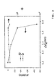
- Fig. 3 is a diagram illustrating the tuning behavior of the oscillator shown in Fig. 2 under the following exemplary conditions:
- the tuning disk 28 is made of sapphire and has a thickness of 0.5 mm. The tuning takes place at a frequency of 23 GHz.
- the y-axis shown in the left-hand image area of FIG. 3 shows the change in the oscillator frequency ⁇ f as a function of the linear stroke ⁇ x 2 of the tuning disk 28 plotted on the x-axis.
- a variation of the linear stroke ⁇ x 2 of 0.75 mm corresponds to a frequency change of 45 MHz.
- the quality Q of the cavity resonator 1, which is plotted on the y axis shown in the right-hand image area of FIG. 3, is largely constant over the entire tuning range of the microwave oscillator and in the example shown here is Q> 2 ⁇ 10 6 . In this case, virtually no degradation of the quality of the cavity resonator 1 occurs during a setting process.
Landscapes
- Control Of Motors That Do Not Use Commutators (AREA)
- Inductance-Capacitance Distribution Constants And Capacitance-Resistance Oscillators (AREA)
- Semiconductor Lasers (AREA)
- Surface Acoustic Wave Elements And Circuit Networks Thereof (AREA)
Description
- Fig. 1:
- eine schematische Schnittdarstellung eines erfindungsgemäßen Hohlraumresonators;
- Fig. 2:
- ein Blockschaltbild eines den in Fig. 1 gezeigten Hohlraumresonator verwendenden Mikrowellenoszillators; und
- Fig. 3
- ein Schaubild, in dem die Änderung der Oszillatorfrequenz Δf als Funktion der Lageänderung Δx2 der Abstimmscheibe dargestellt ist.
Claims (12)
- Abstimmbarer Hohlraumresonator, dergekennzeichnet durch eine Übersetzungsmechanik (18, 20), die die Stelleinrichtung (22, 26) bewegungsmäßig mit der Abstimmscheibe (28) koppelt und einen von der Stelleinrichtung (22, 26) erzeugten Linearhub Δx1 unter vorgegebenem Verhältnis U in einen auf die Abstimmscheibe (28) wirkenden, reduzierten Linearhub Δx2 übersetzt, wobei die Übersetzungsmechanik (18, 20) ein erstes Federelement (20), dessen stelleinrichtungsseitiges Ende mit dem von der Stelleinrichtung (22, 26) erzeugten Linearhub Δx1 auslenkbar ist, und ein zweites Federelement (18), das das stelleinrichtungsferne Ende des ersten Federelements (20) mit einer Gegenkraft beaufschlagt, umfaßt.einen einen Hohlraum (5) definierenden Resonatorkörper (2, 3, 4),eine in ihrer Lage gegenüber dem Resonatorkörper (2, 3, 4) veränderliche und dabei die Resonanzfrequenz ωR des Hohlraumresonators (1) beeinflussende Abstimmscheibe (28) undeine Stelleinrichtung (22, 26) zur mechanischen Lageveränderung der Abstimmscheibe (28) umfaßt,
- Abstimmbarer Hohlraumresonator nach Anspruch 1, dadurch gekennzeichnet, daß das erste Federelement aus wenigstens einer Tellerfeder (20) gebildet ist, und daß das zweite Federelement von einer umfangsseitig fixierten, von der Tellerfeder (20) zentral beaufschlagten Plattenfeder (18) realisiert ist.
- Abstimmbarer Hohlraumresonator nach Anspruch 2, dadurch gekennzeichnet,daß der Resonatorkörper aus einer zylindrischen Umfangswand (3), einer Deckenwand (4) und einer Bodenwand (2) besteht,daß in der Deckenwand (4) und/oder der Bodenwand (2) ein zur Umfangswandachse koaxialer, einen Tellerfederstapel (20) enthaltender zylindrischer Federaufnahmeraum (19) ausgebildet ist, und daß die Plattenfeder (18) in ihrem radial äußeren Bereich zwischen einem Flansch (15) der Umfangswand (3) und der Decken- oder Bodenwand (4; 2) fixiert ist.
- Abstimmbarer Hohlraumresonator nach einem der vorhergehenden Ansprüche, dadurch gekennzeichnet, daß die Stelleinrichtung (22, 26) ein insbesondere manuell betätigbares mechanisches Stellglied, insbesondere Drehstellglied (22) und ein dem mechanischen Stellglied (22) nachgeschaltetes erstes elektromechanisches Stellglied, insbesondere erstes Piezbelement (26) umfaßt.
- Abstimmbarer Hohlraumresonator nach Anspruch 3, dadurch gekennzeichnet, daß zwischen dem Flansch (15) der Umfangswand (3) und der Boden- und/oder Deckenwand (2; 4) eine oder mehrere Abstandselemente (9; 14) vorgegebener Stärke angeordnet sind.
- Abstimmbarer Hohlraumresonator nach einem der vorhergehenden Ansprüche, dadurch gekennzeichnet, daß die Abstimmscheibe (28) aus einem dielektrischen Material, insbesondere Saphir, besteht.
- Abstimmbarer Hohlraumresonator nach einem der vorhergehenden Ansprüche, dadurch gekennzeichnet,daß in dem Resonatorkörper (2, 3, 4) ein dielektrischer Körper (30) vorgesehen ist, unddaß die Abstimmscheibe (28) innerhalb des Resonatorkörpers (2, 3, 4) unter einem geringen Abstand d zu einer ebenen Oberfläche (29) des dielektrischen Körpers (30) angeordnet ist.
- Abstimmbarer Hohlraumresonator nach Anspruch 7, dadurch gekennzeichnet, daß der dielektrische Körper (30) auf einem mittels eines zweiten elektromechanischen Stellglieds, insbesondere zweiten Piezoelements (11) in seiner Höhe veränderlichen Hubboden (10) angebracht ist.
- Abstimmbarer Hohlraumresonator nach einem der vorhergehenden Ansprüche, dadurch gekennzeichnet, daß das erste und/oder das zweite elektromechanische Stellglied (11; 26) ein von einer Ansteuerschaltung ausgegebenes elektrisches Steuersignal empfängt, mittels dem der Hohlraumresonator (1) in einem Frequenz-Regelschleifenbetrieb betrieben wird.
- Abstimmbarer Hohlraumresonator nach einem der vorhergehenden Ansprüche, dadurch gekennzeichnet, daß der Hohlraumresonator (1) thermisch an eine externe Kühleinrichtung, insbesondere einen mechanischen Kleinkühler angeschlossen ist.
- Abstimmbarer Mikrowellenoszillator mit einem Hohlraumresonator nach einem der vorhergehenden Ansprüche, gekennzeichnet durch einen Verstärker (40), der ein den Hohlraumresonator (1) anregendes Verstärkersignal (41) ausgibt, einen Phasenschieber (45), der ein aus dem Hohlraumresonator (1) ausgekoppeltes Ausgangssignal (44) entgegennimmt und ein gegenüber dem Ausgangssignal (44) phasenverschiebbares Rückkoppelsignal (46) bereitstellt, welches einem Eingang des Verstärkers (40) zugeführt wird.
- Abstimmbarer Mikrowellenoszillator nach Anspruch 11, dadurch gekennzeichnet, daß der Hohlraumresonator 1 eine Güte Q > 106, insbesondere Q > 107 aufweist, und daß die Übersetzungsmechanik (18, 20) des Hohlraumresonators (1) so ausgelegt ist, daß die durch eine minimal mögliche Verstellung der Stelleinrichtung (22) erzielbare Minimaländerung der Resonanzfrequenz ΔωR(min) kleiner als der durch eine Verstellung des Phasenschiebers (45) maximal erzielbare Frequenzhub ΔωR der Resonanzfrequenz ωR ist.
Applications Claiming Priority (3)
| Application Number | Priority Date | Filing Date | Title |
|---|---|---|---|
| DE19841078 | 1998-09-09 | ||
| DE19841078A DE19841078C1 (de) | 1998-09-09 | 1998-09-09 | Abstimmbarer Hohlraumresonator |
| PCT/EP1999/005959 WO2000014823A1 (de) | 1998-09-09 | 1999-08-13 | Abstimmbarer hohlraumresonator |
Publications (2)
| Publication Number | Publication Date |
|---|---|
| EP1112603A1 EP1112603A1 (de) | 2001-07-04 |
| EP1112603B1 true EP1112603B1 (de) | 2003-07-09 |
Family
ID=7880286
Family Applications (1)
| Application Number | Title | Priority Date | Filing Date |
|---|---|---|---|
| EP99944392A Expired - Lifetime EP1112603B1 (de) | 1998-09-09 | 1999-08-13 | Abstimmbarer hohlraumresonator |
Country Status (5)
| Country | Link |
|---|---|
| US (1) | US6549104B1 (de) |
| EP (1) | EP1112603B1 (de) |
| AT (1) | ATE244939T1 (de) |
| DE (2) | DE19841078C1 (de) |
| WO (1) | WO2000014823A1 (de) |
Families Citing this family (13)
| Publication number | Priority date | Publication date | Assignee | Title |
|---|---|---|---|---|
| JP2002026602A (ja) * | 2000-07-10 | 2002-01-25 | Murata Mfg Co Ltd | 誘電体共振器装置、フィルタ、デュプレクサおよび通信装置 |
| FI122012B (fi) * | 2006-04-27 | 2011-07-15 | Filtronic Comtek Oy | Virityselin ja viritettävä resonaattori |
| US8123399B2 (en) * | 2007-05-08 | 2012-02-28 | The United States of America as represented by the National Institute of Standards and Technology | Dielectric resonator thermometer and a method of using the same |
| DE102007027372A1 (de) * | 2007-06-11 | 2008-12-18 | Cognis Oleochemicals Gmbh | Verfahren zur Hydrierung von Glycerin |
| DE102007027371A1 (de) * | 2007-06-11 | 2008-12-18 | Cognis Oleochemicals Gmbh | Verfahren zur Herstellung einer Verbindung aufweisend mindestens eine Ester-Gruppe |
| GB2452293B (en) * | 2007-08-30 | 2011-09-28 | Isotek Electronics Ltd | A tuneable filter and a method of tuning such a filter |
| US8410792B2 (en) * | 2009-03-02 | 2013-04-02 | Forschungszentrum Juelich Gmbh | Resonator arrangement and method for analyzing a sample using the resonator arrangement |
| US8711361B2 (en) * | 2009-11-05 | 2014-04-29 | Qualcomm, Incorporated | Methods and devices for detecting and measuring environmental conditions in high performance device packages |
| DE102014218814B4 (de) * | 2014-09-18 | 2017-11-16 | Hauni Maschinenbau Gmbh | Mikrowellenstrangmessvorrichtung, Verfahren und Verwendung |
| WO2018119306A1 (en) * | 2016-12-22 | 2018-06-28 | Knowles Cazenovia, Inc. | Microwave cavity resonator stabilized oscillator |
| US11133567B2 (en) * | 2019-09-30 | 2021-09-28 | Nokia Shanghai Bell Co., Ltd. | Capacitive coupling tuner |
| CN115000666B (zh) * | 2022-06-27 | 2024-04-19 | 国仪量子技术(合肥)股份有限公司 | 谐振腔 |
| CN119966375B (zh) * | 2024-12-30 | 2025-12-05 | 北京无线电计量测试研究所 | 一种高q值频率可调谐蓝宝石微波腔 |
Family Cites Families (9)
| Publication number | Priority date | Publication date | Assignee | Title |
|---|---|---|---|---|
| US3121205A (en) * | 1960-05-05 | 1964-02-11 | Varian Associates | Tunable cavity having deformable wall that pivots about the edge of a constraining member during flexure |
| US3213393A (en) * | 1963-05-03 | 1965-10-19 | Westinghouse Electric Corp | Cavity device |
| GB1072574A (en) * | 1964-04-01 | 1967-06-21 | English Electric Valve Co Ltd | Improvements in or relating to microwave tuning devices |
| US4178562A (en) * | 1977-01-10 | 1979-12-11 | Tavkozlesi Kutato Intezet | Cavity resonators with frequency-linear tuning |
| JPS61280104A (ja) * | 1985-06-05 | 1986-12-10 | Murata Mfg Co Ltd | 誘電体共振器装置 |
| FI97088C (fi) * | 1994-10-05 | 1996-10-10 | Nokia Telecommunications Oy | Dielektrinen resonaattori |
| FI97090C (fi) * | 1994-10-05 | 1996-10-10 | Nokia Telecommunications Oy | Dielektrinen resonaattori |
| US5859576A (en) * | 1996-03-29 | 1999-01-12 | Illinois Superconductor Corporation | Extended spring loaded tuner |
| SE9702063D0 (sv) * | 1997-05-30 | 1997-05-30 | Ericsson Telefon Ab L M | Filter tuning arrangement |
-
1998
- 1998-09-09 DE DE19841078A patent/DE19841078C1/de not_active Expired - Fee Related
-
1999
- 1999-08-13 DE DE59906271T patent/DE59906271D1/de not_active Expired - Fee Related
- 1999-08-13 EP EP99944392A patent/EP1112603B1/de not_active Expired - Lifetime
- 1999-08-13 US US09/786,760 patent/US6549104B1/en not_active Expired - Fee Related
- 1999-08-13 AT AT99944392T patent/ATE244939T1/de not_active IP Right Cessation
- 1999-08-13 WO PCT/EP1999/005959 patent/WO2000014823A1/de not_active Ceased
Also Published As
| Publication number | Publication date |
|---|---|
| EP1112603A1 (de) | 2001-07-04 |
| ATE244939T1 (de) | 2003-07-15 |
| DE59906271D1 (de) | 2003-08-14 |
| DE19841078C1 (de) | 2000-05-18 |
| US6549104B1 (en) | 2003-04-15 |
| WO2000014823A1 (de) | 2000-03-16 |
Similar Documents
| Publication | Publication Date | Title |
|---|---|---|
| DE19841078C1 (de) | Abstimmbarer Hohlraumresonator | |
| DE2714244C2 (de) | ||
| WO2008009326A1 (de) | Hochfrequenzfilter in koaxialer bauweise | |
| DE4236769C2 (de) | Dielektrisches Resonatorbauelement | |
| EP1000314A2 (de) | Abstandsmessvorrichtung und verfahren zur bestimmung eines abstands | |
| DE10297591T5 (de) | Resonatorabstimmungsanordnung und -verfahren | |
| DE69432070T2 (de) | Miniaturisierte supraleitende dielektrische Resonatorfilter und Verfahren zu ihrem Betrieb | |
| DE1766111C3 (de) | Hohlraumresonator | |
| DE69216531T2 (de) | Mikrowellenoszillatoren und Sender mit Frequenzstabilisierung | |
| DE69206951T2 (de) | Dielektrischer resonator | |
| DE69216982T2 (de) | Struktur für einen dielektrischen resonator | |
| DE2828928A1 (de) | Einrichtung zur kombination von hochfrequenzenergie | |
| DE69110494T2 (de) | Abstimmbarer Mikrowellenfilter. | |
| EP1603187B1 (de) | Hohlraumresonator, Verwendung eines Hohlraumresonators und Oszillatorschaltung | |
| DE19723286A1 (de) | Vorrichtung zur Filterung von Hochfrequenzsignalen | |
| DE2132871A1 (de) | Magnetron | |
| DE3608471C2 (de) | ||
| DE3938726C2 (de) | Phasendrehglied | |
| DE69714029T2 (de) | Anordnung mit verteilten elementen für differenzschaltung | |
| DE69218669T2 (de) | Mikrowellen-Resonanzhohlraum mit zwei dielektrischen Resonatoren und abstimmbarer Resonanzfrequenz | |
| DE3813865C2 (de) | Aktiver 360 DEG -Phasenschieber mit stufenlos einstellbarer Phase | |
| EP0901692B1 (de) | Verfahren zur abstimmung von planaren supraleitenden filtern | |
| DE1491504C (de) | Reflexklystron | |
| DE19713902C2 (de) | Einrichtung zum verlustarmen Auskoppeln von Zwischenfrequenz-Signals aus einem Terahertz-Mischer | |
| DE2943928A1 (de) | Gunndiode-hohlleiteroszillator |
Legal Events
| Date | Code | Title | Description |
|---|---|---|---|
| PUAI | Public reference made under article 153(3) epc to a published international application that has entered the european phase |
Free format text: ORIGINAL CODE: 0009012 |
|
| 17P | Request for examination filed |
Effective date: 20010324 |
|
| AK | Designated contracting states |
Kind code of ref document: A1 Designated state(s): AT BE CH CY DE DK ES FI FR GB GR IE IT LI LU MC NL PT SE |
|
| RAP1 | Party data changed (applicant data changed or rights of an application transferred) |
Owner name: ROBERT BOSCH GMBH Owner name: FORSCHUNGSZENTRUM JUELICH GMBH |
|
| GRAH | Despatch of communication of intention to grant a patent |
Free format text: ORIGINAL CODE: EPIDOS IGRA |
|
| RAP1 | Party data changed (applicant data changed or rights of an application transferred) |
Owner name: FORSCHUNGSZENTRUM JUELICH GMBH Owner name: TESAT-SPACECOM GMBH & CO. KG |
|
| GRAH | Despatch of communication of intention to grant a patent |
Free format text: ORIGINAL CODE: EPIDOS IGRA |
|
| GRAA | (expected) grant |
Free format text: ORIGINAL CODE: 0009210 |
|
| AK | Designated contracting states |
Designated state(s): AT BE CH CY DE DK ES FI FR GB GR IE IT LI LU MC NL PT SE |
|
| PG25 | Lapsed in a contracting state [announced via postgrant information from national office to epo] |
Ref country code: NL Free format text: LAPSE BECAUSE OF FAILURE TO SUBMIT A TRANSLATION OF THE DESCRIPTION OR TO PAY THE FEE WITHIN THE PRESCRIBED TIME-LIMIT Effective date: 20030709 Ref country code: IT Free format text: LAPSE BECAUSE OF FAILURE TO SUBMIT A TRANSLATION OF THE DESCRIPTION OR TO PAY THE FEE WITHIN THE PRESCRIBED TIME-LIMIT;WARNING: LAPSES OF ITALIAN PATENTS WITH EFFECTIVE DATE BEFORE 2007 MAY HAVE OCCURRED AT ANY TIME BEFORE 2007. THE CORRECT EFFECTIVE DATE MAY BE DIFFERENT FROM THE ONE RECORDED. Effective date: 20030709 Ref country code: IE Free format text: LAPSE BECAUSE OF FAILURE TO SUBMIT A TRANSLATION OF THE DESCRIPTION OR TO PAY THE FEE WITHIN THE PRESCRIBED TIME-LIMIT Effective date: 20030709 Ref country code: GB Free format text: LAPSE BECAUSE OF FAILURE TO SUBMIT A TRANSLATION OF THE DESCRIPTION OR TO PAY THE FEE WITHIN THE PRESCRIBED TIME-LIMIT Effective date: 20030709 Ref country code: FR Free format text: LAPSE BECAUSE OF FAILURE TO SUBMIT A TRANSLATION OF THE DESCRIPTION OR TO PAY THE FEE WITHIN THE PRESCRIBED TIME-LIMIT Effective date: 20030709 Ref country code: FI Free format text: LAPSE BECAUSE OF FAILURE TO SUBMIT A TRANSLATION OF THE DESCRIPTION OR TO PAY THE FEE WITHIN THE PRESCRIBED TIME-LIMIT Effective date: 20030709 Ref country code: ES Free format text: LAPSE BECAUSE OF FAILURE TO SUBMIT A TRANSLATION OF THE DESCRIPTION OR TO PAY THE FEE WITHIN THE PRESCRIBED TIME-LIMIT Effective date: 20030709 |
|
| REG | Reference to a national code |
Ref country code: GB Ref legal event code: FG4D Free format text: NOT ENGLISH |
|
| REG | Reference to a national code |
Ref country code: CH Ref legal event code: EP |
|
| PG25 | Lapsed in a contracting state [announced via postgrant information from national office to epo] |
Ref country code: LU Free format text: LAPSE BECAUSE OF NON-PAYMENT OF DUE FEES Effective date: 20030813 Ref country code: CY Free format text: LAPSE BECAUSE OF FAILURE TO SUBMIT A TRANSLATION OF THE DESCRIPTION OR TO PAY THE FEE WITHIN THE PRESCRIBED TIME-LIMIT Effective date: 20030813 Ref country code: AT Free format text: LAPSE BECAUSE OF NON-PAYMENT OF DUE FEES Effective date: 20030813 |
|
| REF | Corresponds to: |
Ref document number: 59906271 Country of ref document: DE Date of ref document: 20030814 Kind code of ref document: P |
|
| REG | Reference to a national code |
Ref country code: IE Ref legal event code: FG4D Free format text: GERMAN |
|
| PG25 | Lapsed in a contracting state [announced via postgrant information from national office to epo] |
Ref country code: MC Free format text: LAPSE BECAUSE OF NON-PAYMENT OF DUE FEES Effective date: 20030831 Ref country code: LI Free format text: LAPSE BECAUSE OF NON-PAYMENT OF DUE FEES Effective date: 20030831 Ref country code: CH Free format text: LAPSE BECAUSE OF NON-PAYMENT OF DUE FEES Effective date: 20030831 Ref country code: BE Free format text: LAPSE BECAUSE OF NON-PAYMENT OF DUE FEES Effective date: 20030831 |
|
| PG25 | Lapsed in a contracting state [announced via postgrant information from national office to epo] |
Ref country code: SE Free format text: LAPSE BECAUSE OF FAILURE TO SUBMIT A TRANSLATION OF THE DESCRIPTION OR TO PAY THE FEE WITHIN THE PRESCRIBED TIME-LIMIT Effective date: 20031009 Ref country code: GR Free format text: LAPSE BECAUSE OF FAILURE TO SUBMIT A TRANSLATION OF THE DESCRIPTION OR TO PAY THE FEE WITHIN THE PRESCRIBED TIME-LIMIT Effective date: 20031009 Ref country code: DK Free format text: LAPSE BECAUSE OF FAILURE TO SUBMIT A TRANSLATION OF THE DESCRIPTION OR TO PAY THE FEE WITHIN THE PRESCRIBED TIME-LIMIT Effective date: 20031009 |
|
| NLV1 | Nl: lapsed or annulled due to failure to fulfill the requirements of art. 29p and 29m of the patents act | ||
| PG25 | Lapsed in a contracting state [announced via postgrant information from national office to epo] |
Ref country code: PT Free format text: LAPSE BECAUSE OF FAILURE TO SUBMIT A TRANSLATION OF THE DESCRIPTION OR TO PAY THE FEE WITHIN THE PRESCRIBED TIME-LIMIT Effective date: 20031209 |
|
| GBV | Gb: ep patent (uk) treated as always having been void in accordance with gb section 77(7)/1977 [no translation filed] |
Effective date: 20030709 |
|
| REG | Reference to a national code |
Ref country code: IE Ref legal event code: FD4D |
|
| BERE | Be: lapsed |
Owner name: *TESAT-SPACECOM G.M.B.M. & CO. K.G. Effective date: 20030831 Owner name: FORSCHUNGSZENTRUM *JULICH G.M.B.H. Effective date: 20030831 |
|
| PG25 | Lapsed in a contracting state [announced via postgrant information from national office to epo] |
Ref country code: DE Free format text: LAPSE BECAUSE OF NON-PAYMENT OF DUE FEES Effective date: 20040302 |
|
| REG | Reference to a national code |
Ref country code: CH Ref legal event code: PL |
|
| PLBE | No opposition filed within time limit |
Free format text: ORIGINAL CODE: 0009261 |
|
| STAA | Information on the status of an ep patent application or granted ep patent |
Free format text: STATUS: NO OPPOSITION FILED WITHIN TIME LIMIT |
|
| 26N | No opposition filed |
Effective date: 20040414 |
|
| EN | Fr: translation not filed |