EP1112700A2 - Reissverschluss - Google Patents
Reissverschluss Download PDFInfo
- Publication number
- EP1112700A2 EP1112700A2 EP00128146A EP00128146A EP1112700A2 EP 1112700 A2 EP1112700 A2 EP 1112700A2 EP 00128146 A EP00128146 A EP 00128146A EP 00128146 A EP00128146 A EP 00128146A EP 1112700 A2 EP1112700 A2 EP 1112700A2
- Authority
- EP
- European Patent Office
- Prior art keywords
- fastener
- fastener element
- coating layer
- metallic coating
- slide fastener
- Prior art date
- Legal status (The legal status is an assumption and is not a legal conclusion. Google has not performed a legal analysis and makes no representation as to the accuracy of the status listed.)
- Granted
Links
Images


Classifications
-
- A—HUMAN NECESSITIES
- A44—HABERDASHERY; JEWELLERY
- A44B—BUTTONS, PINS, BUCKLES, SLIDE FASTENERS, OR THE LIKE
- A44B19/00—Slide fasteners
- A44B19/02—Slide fasteners with a series of separate interlocking members secured to each stringer tape
- A44B19/04—Stringers arranged edge-to-edge when fastened, e.g. abutting stringers
-
- A—HUMAN NECESSITIES
- A44—HABERDASHERY; JEWELLERY
- A44B—BUTTONS, PINS, BUCKLES, SLIDE FASTENERS, OR THE LIKE
- A44B19/00—Slide fasteners
- A44B19/42—Making by processes not fully provided for in one other class, e.g. B21D53/50, B21F45/18, B22D17/16, B29D5/00
- A44B19/52—Securing the interlocking members to stringer tapes while making the latter
- A44B19/54—Securing the interlocking members to stringer tapes while making the latter while weaving the stringer tapes
-
- A—HUMAN NECESSITIES
- A44—HABERDASHERY; JEWELLERY
- A44B—BUTTONS, PINS, BUCKLES, SLIDE FASTENERS, OR THE LIKE
- A44B19/00—Slide fasteners
-
- A—HUMAN NECESSITIES
- A44—HABERDASHERY; JEWELLERY
- A44B—BUTTONS, PINS, BUCKLES, SLIDE FASTENERS, OR THE LIKE
- A44B19/00—Slide fasteners
- A44B19/10—Slide fasteners with a one-piece interlocking member on each stringer tape
- A44B19/12—Interlocking member in the shape of a continuous helix
-
- A—HUMAN NECESSITIES
- A44—HABERDASHERY; JEWELLERY
- A44B—BUTTONS, PINS, BUCKLES, SLIDE FASTENERS, OR THE LIKE
- A44B19/00—Slide fasteners
- A44B19/42—Making by processes not fully provided for in one other class, e.g. B21D53/50, B21F45/18, B22D17/16, B29D5/00
- A44B19/44—Securing metal interlocking members to ready-made stringer tapes
- A44B19/50—Securing one-piece interlocking members
-
- A—HUMAN NECESSITIES
- A44—HABERDASHERY; JEWELLERY
- A44B—BUTTONS, PINS, BUCKLES, SLIDE FASTENERS, OR THE LIKE
- A44B19/00—Slide fasteners
- A44B19/42—Making by processes not fully provided for in one other class, e.g. B21D53/50, B21F45/18, B22D17/16, B29D5/00
- A44B19/52—Securing the interlocking members to stringer tapes while making the latter
- A44B19/56—Securing the interlocking members to stringer tapes while making the latter while knitting the stringer tapes
-
- Y—GENERAL TAGGING OF NEW TECHNOLOGICAL DEVELOPMENTS; GENERAL TAGGING OF CROSS-SECTIONAL TECHNOLOGIES SPANNING OVER SEVERAL SECTIONS OF THE IPC; TECHNICAL SUBJECTS COVERED BY FORMER USPC CROSS-REFERENCE ART COLLECTIONS [XRACs] AND DIGESTS
- Y10—TECHNICAL SUBJECTS COVERED BY FORMER USPC
- Y10T—TECHNICAL SUBJECTS COVERED BY FORMER US CLASSIFICATION
- Y10T24/00—Buckles, buttons, clasps, etc.
- Y10T24/25—Zipper or required component thereof
- Y10T24/2539—Interlocking surface constructed from plural elements in series
Definitions
- the invention relates to a slide fastener and more particularly to a slide fastener including fastener elements made of synthetic resin or metal having a surface coated with a metallic coating layer so that it is glossy and ornamentally beautiful.
- an entire surface of a coil-shaped fastener element or zigzag-shaped fastener element made of synthetic resin monofilament is coated with a metallic coating layer having a gloss peculiar to metal.
- a fastener element of synthetic resin mono-filament attached to a fastener tape and an exposed portion of a core cord being seen inserted within the fastener element are coated with a metallic coating layer.
- an object of the invention is to provide a side fastener comprising a fastener element in which when it is intended to form a metallic coating layer on a fastener element made of synthetic resin or metal, such a phenomenon that the metallic coating layer is scraped and that metallic powder is scattered is prevented by canceling formation of the metallic coating layer on an outer side face of the fastener element with which a guide flange of a slider makes contact, thereby securing a metallic coating layer having a beautiful appearance.
- Another object of the invention is to provide a slide fastener comprising a fastener element in which such a fear that the metallic powder are scattered is prevented by also canceling formation of the metallic coating layer on an outer side face of a coupling head, which makes contact with a guide post of the fastener element, thereby securing a metallic coating layer having a beautiful appearance.
- Another object of the invention is to provide a slide fastener comprising a fastener element in which a metallic coating layer having a different beautiful appearance depending thereon is formed by specifying the shape of the fastener element.
- Another object of the invention is to provide a slide fastener comprising a fastener element in which a metallic coating layer having a different beautiful appearance depending thereon is formed by specifying the shape of the slide fastener.
- Further object of the invention is to provide a slide fastener in which a metallic coating layer formed on the fastener element can be made to function effectively by specifying the configuration of sewing yarn, weaving yarn and warp knitting yarn for attaching and fixing the fastener element onto a fastener tape.
- And further object of the invention is to provide a slide fastener in which the metallic coating layer formed on the surface of the fastener element can be protected effectively by using a slider formed by die-casting or injection molding, which has been said to have a defect.
- a slide fastener having a pair of fastener stringers to which fastener elements are attached along facing edge portions of a pair of fastener tapes in the longitudinal direction and a slider which is slidable along the fastener elements and can couple or separate the fastener elements, wherein a metallic coating layer is formed on a top surface of a fastener element except an outer side face thereof in contact with a guide flange of the slider.
- the metallic coating layer is formed on the top surface of the fastener element attached to the fastener tape, made of synthetic resin or metal, except an outer side face of a coupling head of the fastener element in contact with a guide post of the slider.
- the fastener element which is to be attached to the fastener tape and comprises the metallic coating layer, is formed of coil-shaped fastener elements formed by winding synthetic resin monofilament in the shape of coil.
- the fastener element which is to be attached to the fastener tape 10 and comprises the metallic coating layer, is formed of zigzag-shaped fastener elements formed by bending synthetic resin monofilament in the shape of zigzag.
- the fastener element which is to be attached to the fastener tape and comprises the metallic coating layer, is formed of single-unit injection-molded fastener elements formed by injection molding synthetic resin.
- the fastener element which is to be attached to the fastener tape and comprises the metallic coating layer, is formed of single-unit metallic fastener elements formed by shearing or die-casting metal.
- the fastener element comprising the metallic coating layer
- the fastener element is sewed to a side edge of the fastener tape with sewing yarn, thereby securing a metallic gloss.
- the fastener element comprising the metallic coating layer
- the fastener element is woven into a side edge of the fastener tape with weaving yarn, thereby securing a metallic gloss.
- the fastener element comprising the metallic coating layer
- the fastener element is knitted into a side edge of the fastener tape with warp knitting yarn, thereby securing a metallic gloss.
- the sewing yarn, weaving yarn and warp knitting yarn, disposed on top of the fastener element comprising the metallic coating layer for fixing the fastener element onto the fastener tape is formed of a transparent yarn or a yarn having a color similar to that of the metallic coating layer, thereby improving the function of the metallic coating layer.
- the slider is formed by die-casting or injection molding using metal or synthetic resin, thereby securing a metallic gloss.
- Fig. 1 is a perspective view of a coil-shaped fastener element made of synthetic resin.
- Fig. 2 is a front view of a slide fastener comprising the coil-shaped fastener element.
- Fig. 3 is a sectional view of the slide fastener comprising the coil-shaped fastener element of Fig. 2.
- Fig. 4 is a sectional view of a fastener stringer comprising the coil-shaped fastener element.
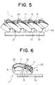
- Fig. 5 is a side view of a fastener stringer comprising the coil-shaped fastener element of Fig. 4.
- Fig. 6 is a sectional view of a fastener stringer comprising the coil-shaped fastener element having no core cord.
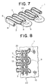
- Fig. 7 is a perspective view of a zigzag-shaped fastener element made of synthetic resin.
- Fig. 8 is a front view of a fastener stringer comprising the zigzag-shaped fastener element.
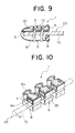
- Fig. 9 is a sectional view of a fastener stringer comprising the zigzag-shaped fastener element of Fig. 8.
- Fig. 10 is a perspective view of a fastener stringer comprising an injected fastener element made of synthetic resin.
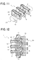
- Fig. 11 is a perspective view of a fastener stringer comprising a metallic fastener element made of metal.
- Fig. 12 is a front view of a woven-in fastener stringer.
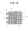
- Fig. 13 is a front view of a knitted-in fastener stringer.
- the slide fastener has a pair of fastener stringers 23, 23, to which fastener elements 1, 1 are attached along facing side edge portions of a pair of fastener tapes 10, 10 in a longitudinal direction, the fastener tapes 10, 10 being woven or knitted with synthetic fiber such as polyester or nylon, or natural fiber such as cotton, and a slider 17 which is slidable along the fastener elements 1, 1 and can couple or separate the fastener elements 1, 1.
- a fastener element 1 for the slide fastener is formed of synthetic resin such as polyamide, polyester and the like.
- the fastener element 1 of a first embodiment of the invention forms a coil-shaped fastener element 2 by winding synthetic resin monofilament in the shape of coil.
- This coil-shaped fastener element 2 is comprised of coupling head 6, upper leg portion 7, lower leg portion 8, and inverted portion 9 for connecting the upper leg portion 7 with the lower leg portion 8.
- a metallic coating layer 20 is formed on a surface of the upper leg portion 7 except an outer side face of the coupling head 6, an outer side face of the inverted portion 9, and the lower leg portion 8.
- the metallic coating layer 20 is formed by depositing aluminum, chrome, nickel, stainless, gold, silver, copper, brass or the like in the form of a thin film or creating a metallic coating by vacuum deposition, ion plating, sputtering, chemical plating or the like.
- this metallic coating layer 20 is formed in thickness of 0.001 to 1 ⁇ m.
- a core cord 11 is inserted into the coil-shaped fastener element 2 comprising the metallic coating layer 20 and then, the fastener element 2 is sewed to a side edge of a fastener tape 10 with the sewing yarn 12 by double ring sewing system using three yarns by two needles so as to form a fastener stringer 23.
- a slider 17 is placed to catch right and left fastener stringers 23 and the right and left coupling heads 6 are engaged with each other to form the slider fastener by sliding the slider 17.
- the slider 17 made of metal is formed by die-casting or made of synthetic resin is formed by injection. As shown in Figs. 2 and 3, in the slider 17 an upper wing plate 33 and a lower wing plate 34 disposed in parallel on the side of a shoulder 31 are connected by a guide post 18, and an element guide groove 36, in which the fastener element 2 may be inserted, is provided between respective plates.
- a long guide flange 19 being protruded toward the lower wing plate 34 is formed on both of side edge portions of the upper wing plate 33.
- short guide flanges being slightly protruded toward the upper wing plate 33 are also formed on both of side edge portions of the lower wing plate 34 in the shown embodiment, the short guide flange may be omitted, if necessary.
- a zipper pull attaching portion 32 is fixed to a surface of the upper wing plate 33, and a zipper pull 35 is attached thereto so as to swing freely.
- Above-described guide flange 19 of the slider 17 has a shape suitable for the coil-shaped fastener element 2, but guide flanges disposed on the upper and lower wing plates 33, 34 are respectively protruded toward the other plate with a same length, in a zigzag-shaped fastener element 3 or single-body fastener elements 4 and 5 made of metal or synthetic resin, which will be described later.
- the metallic coating layer 20 is formed on the surface of the upper leg portion 7 of the coil-shaped fastener element 2 and not formed positively on the outer side face of the coupling head 6 and the outer side face of the inverted portion 9. As for the reason, small burrs in a parting line often exists in an inner face of the guide flange 19 of the slider 17 formed by die-casting or injection and even if the metallic coating layer 20 is formed on the surface of the coil-shaped fastener element 2, when the slider 17 is slid, the burrs on the guide flange 19 scrapes the deposited metallic coating layer 20 from the inverted portion 9, thereby scattering metallic powder. Further, the metallic coating layer 20 may be peeled from an outer side face of the coupling head 6, which comes into contact with the guide post 18 of the slider 17, so there is a fear that metallic powder may be scattered.
- the sewing yarn 12 which is colorless transparent or has a color similar to that of the metallic coating layer 20 favorably the sewing yarn 12 does not attract much attention in the coil-shaped fastener element 2 having the metallic coating layer 20.
- the coil-shaped fastener element 2 is formed by winding synthetic resin monofilament in the shape of coil.
- the metallic coating layer 20 is formed on the surface of the upper leg portion 7 and not formed on the outer side face of the coupling head 6, the outer side face of the inverted portion 9, and the lower leg portion 8.
- the coil-shaped fastener element 2 is sewed to the fastener tape 10 by double ring sewing system without core cord, and colorless transparent or white color yarn is used as the sewing yarn 12.
- This fastener stringer 23 also prevents the peeling off or scrapping of the metallic coating layer 20 and the scattering of the metallic powder.
- the fastener element 1 of a third embodiment of the present invention shown in Fig. 7 is a zigzag-shaped fastener element 3 formed by bending synthetic resin monofilament in the shape of zigzag and turning back with respect to the center thereof.
- This zigzag-shaped fastener element 3 is comprised of the coupling head 6, upper leg portion 7 and lower leg portion 8 connected to the coupling head 6, and inverted portion 9 for connecting the leg portions 7 and 8 to the adjacent ones.
- the metallic coating layer 20 is formed on the surface of the upper leg portion 7 except the outer side face of the coupling head 6, the outer side face of the inverted portion 9 of the upper leg portion 7 and the lower leg portion 8 and inverted portion 9 of the lower leg portion 8, like the first embodiment.
- a side edge of the fastener tape 10 is sandwiched by the upper leg portion 7 and lower leg portion 8 and the upper and lower leg portions 7 and 8 are sewed to the fastener tape 10 with the sewing yarn 12 by arranging the double ring sewing system using two yarns by a single needle in parallel to each other, so as to form the fastener stringer 23.
- the sewing yarn 12 which is colorless transparent or has a color similar to that of the metallic coating layer 20 is used, the metallic gloss of the metallic coating layer 20 looks beautiful. Further, it is permissible to dispose the looper yarn and needle yarn of the double ring sewing system in reverse.
- the zigzag-shaped fastener element 3 also, even if the guide flange 19 comes into contact with the outer side face of the inverted portion 9 of the upper leg portion 7 or the guide post 18 comes into contact with the outer side face of the coupling head 6 when the slider 17 slides, there is no fear that the metallic coating layer 20 may be peeled or scraped by the guide flange 19 or the guide post 18, because the metallic coating layer 20 is not formed on the outer side face of the inverted portion 9 and the outer side face of the coupling head 6. Meanwhile, it is permissible to sew the zigzag-shaped fastener element 3 on a side edge of the fastener tape 10 to be placed thereon.
- a single-body injection-molded fastener element 4 is formed on a swollen edge portion of a side edge of the fastener tape 10 by an injection molding means using such synthetic resin as polyamide, polyester, polyacetal, polypropylene and polybutylene terphthalate.
- the injection-molded fastener element 4 is comprised of the coupling head 6, upper leg portion 7 and lower leg portion 8.
- a concave portion in which the coupling head 6 of a corresponding injection-molded fastener element 4 can engage is formed between the coupling head 6a/6b and upper/lower leg portions 7 and 8.
- the metallic coating layer 20 is also formed on the upper leg portion 7 and coupling head 6 except the outer side faces of the upper leg portion 7 and coupling head 6 like the first embodiment. If the slider 17 is placed to catch the right and left fastener stringers 23 and then slid, the outer side face of the upper leg portion 7 of the injection-molded fastener element 4 comes into contact with the guide flange 19 of the slider 17. Also the outer side face of the coupling head 6 comes into contact with the guide post 18. However, there is no fear that metallic powder may be scattered because no metallic coating layer 20 is formed on any place of them.
- the fastener element 1 of a fifth embodiment of the invention shown in Fig. 11 is a metallic fastener element 5 formed by die-casting or shearing of metal such as aluminum alloy and zinc alloy.
- This metallic fastener element 5 is attached to the swollen edge portion on a side edge of the fastener tape 10 by crimping so as to form the fastener stringer 23.
- the metallic fastener element 5 is comprised of the coupling head 6, upper leg portion 7 and lower leg portion 8.
- the metallic coating layer 20 is formed on a top face of the coupling head 6 and the surface of the upper leg portion 7 except the outer side faces of the coupling head 6 and upper leg portion 7.
- a base material of the metallic fastener element 5 is formed of relatively cheap metal such as aluminum alloy and zinc alloy and the metallic coating layer 20 is formed with expensive metal such as gold and silver.
- the fastener element 1 when the fastener element 1 is attached and fixed to the fastener tape 10, the fastener element 1 is woven into a side edge of the fastener tape 10 with the weaving yarn 13. More specifically, the core cord 11 is inserted within the coil-shaped fastener element 2 shown in Fig. 1 and this coil-shaped fastener element 2 is woven into the fastener tape 10 with warp yarn 14 for weaving the fastener tape 10 and weft yarn 15 of double pick.
- a fastener stringer 23 of a seventh embodiment of the invention shown in Fig. 13 when the fastener element 1 is attached and fixed to the fastener tape 10, the fastener element 1 is knitted into a side edge of the fastener tape 10 with the warp knitting yarn 16. More specifically, the coil-shaped fastener element 2 shown in Fig. 1 is knitted into a side edge of the fastener tape 10 having warp knitting structure with warp knitting yarn 16 such as chain knitting yarn, two needle stitch yarn, tricot yarn or the like.
- warp knitting yarn 16 such as chain knitting yarn, two needle stitch yarn, tricot yarn or the like.
- the fastener element 1 by forming the fastener element 1 with colorless transparent material, it does not attract much attention that there is no metallic coating layer 20 on the outer face of the fastener element 1, thereby improving the good appearance of the slide fastener.
- the slider fastener of the present invention has the above-described structure, and the following effects are exerted with this structure.
- the metallic coating layer 20 is formed on the top side surface of the fastener element 1, except the outer side face thereof which makes contact with the guide flange 19 of the slider 17 and the outer side face of the coupling head 6 which makes contact with the guide post 18 of the slider 17.
- the fastener element 1 having a beautiful metallic gloss can be used for a long term and a cheap, fashionable slide fastener can be provided to meet user's demands.
- the invention can be applied to various types of the fastener elements 1, such as the coil-shaped fastener element 2, zigzag-shaped fastener element 3, injection-molded fastener element4, made of synthetic resin and metallic single-unit fastener elements 5.
- the fastener elements 1 having a beautiful metallic gloss can be supplied to satisfy user's demands.
- the fastener element 1 is sewed to a side edge of the fastener tape 10 with sewing yarn 12 or woven into with weaving yarn 13 or knitted into with warp knitting yarn 16.
- the fastener element 1 having a beautiful metallic gloss can be applied to various types of the slide fasteners easily, so that a beautiful slide fastener can be produced.
- the sewing yarn 12, weaving yarn 13 and warp knitting yarn 16 to be disposed on top of the fastener element 1 for fixing the fastener element 1 onto the fastener tape 10 is formed of a transparent yarn or a yarn having a color similar to that of the metallic coating layer 20.
- the yarn does not attract muoh attention, so that without hampering the function of the metallic coating layer 20 of the fastener element 1, the beautiful metallic gloss can look more beautiful.
- the slider 17 is formed by die-casting or injection molding using metal or synthetic resin.
Landscapes
- Slide Fasteners (AREA)
Applications Claiming Priority (2)
| Application Number | Priority Date | Filing Date | Title |
|---|---|---|---|
| JP36907099 | 1999-12-27 | ||
| JP36907099A JP2001178508A (ja) | 1999-12-27 | 1999-12-27 | スライドファスナー用ファスナーエレメント |
Publications (3)
| Publication Number | Publication Date |
|---|---|
| EP1112700A2 true EP1112700A2 (de) | 2001-07-04 |
| EP1112700A3 EP1112700A3 (de) | 2004-02-11 |
| EP1112700B1 EP1112700B1 (de) | 2006-09-20 |
Family
ID=18493487
Family Applications (1)
| Application Number | Title | Priority Date | Filing Date |
|---|---|---|---|
| EP00128146A Expired - Lifetime EP1112700B1 (de) | 1999-12-27 | 2000-12-21 | Reissverschluss |
Country Status (8)
| Country | Link |
|---|---|
| US (1) | US20010004787A1 (de) |
| EP (1) | EP1112700B1 (de) |
| JP (1) | JP2001178508A (de) |
| KR (1) | KR100374942B1 (de) |
| CN (1) | CN1230109C (de) |
| DE (1) | DE60030831T2 (de) |
| ES (1) | ES2270780T3 (de) |
| TW (1) | TW573478U (de) |
Cited By (3)
| Publication number | Priority date | Publication date | Assignee | Title |
|---|---|---|---|---|
| US8765248B2 (en) | 2009-03-27 | 2014-07-01 | Ykk Corporation | Continuous fastener element and fastener stringer |
| EP2856901A4 (de) * | 2012-05-28 | 2016-04-27 | Ykk Corp | Reissverschluss |
| EP3967176A4 (de) * | 2019-05-09 | 2022-05-04 | YKK Corporation | Verschlusskette und reissverschluss |
Families Citing this family (18)
| Publication number | Priority date | Publication date | Assignee | Title |
|---|---|---|---|---|
| TWM245809U (en) * | 2003-12-31 | 2004-10-11 | Jr-Shiung Yu | Suspension decoration |
| JP5043688B2 (ja) | 2008-01-08 | 2012-10-10 | Ykk株式会社 | スライドファスナー |
| WO2012001792A1 (ja) | 2010-06-30 | 2012-01-05 | Ykk株式会社 | スライドファスナー及びスライドファスナーの製造方法 |
| WO2012020499A1 (ja) * | 2010-08-12 | 2012-02-16 | Ykk株式会社 | スライドファスナー |
| US8484764B2 (en) | 2010-08-18 | 2013-07-16 | Under Armour, Inc. | Zipper arrangement |
| JP5606548B2 (ja) * | 2010-11-10 | 2014-10-15 | Ykk株式会社 | ファスナーストリンガー及びスライドファスナー |
| US8484811B2 (en) | 2010-11-16 | 2013-07-16 | Under Armour, Inc. | Zipper arrangement with wheeled slider |
| US8528115B2 (en) | 2010-11-16 | 2013-09-10 | Under Armour, Inc. | Zipper arrangement with foldable pull |
| US8341809B2 (en) | 2010-11-16 | 2013-01-01 | Under Armour, Inc. | Zipper arrangement with funnel grip |
| WO2012081123A1 (ja) | 2010-12-17 | 2012-06-21 | Ykk株式会社 | ファスナーストリンガー及びファスナーチェーン、並びにファスナーチェーンの製造方法 |
| JP5813122B2 (ja) * | 2011-09-21 | 2015-11-17 | Ykk株式会社 | スライドファスナー |
| CN103826493B (zh) * | 2011-10-04 | 2016-03-02 | Ykk株式会社 | 拉链的制造方法和拉链 |
| CN103997927B (zh) * | 2011-12-27 | 2017-06-09 | Ykk株式会社 | 拉链用成型部件及具备该部件的拉链 |
| WO2014016908A1 (ja) * | 2012-07-24 | 2014-01-30 | Ykk株式会社 | スライドファスナー用ファスナーエレメント |
| CN103340494B (zh) * | 2013-07-15 | 2015-06-10 | 王萍煌 | 一种浅金色拉链的制作方法 |
| WO2015166536A1 (ja) * | 2014-04-28 | 2015-11-05 | Ykk株式会社 | ファスナーチェーン、及びその製造方法 |
| US10575601B2 (en) | 2015-10-02 | 2020-03-03 | Under Armour, Inc. | Stop for zipper arrangement |
| AR122711A1 (es) | 2020-06-25 | 2022-09-28 | Alchemedicine Inc | COMPUESTO HETEROCÍCLICO COMO INHIBIDOR DE CASEÍNA QUINASA 1d Y/O QUINASA 5 TIPO RECEPTOR DE ACTIVINA |
Family Cites Families (3)
| Publication number | Priority date | Publication date | Assignee | Title |
|---|---|---|---|---|
| JPS6420805A (en) * | 1987-07-14 | 1989-01-24 | Yoshida Kogyo Kk | Slide fastener |
| JPH07100041B2 (ja) * | 1989-02-20 | 1995-11-01 | ワイケイケイ株式会社 | 装飾務歯をもったスライドファスナーの製造方法 |
| CA2011944C (en) * | 1989-03-16 | 1996-02-20 | Yoshiyuki Horita | Slide fastener and fastener elements therefor |
-
1999
- 1999-12-27 JP JP36907099A patent/JP2001178508A/ja active Pending
-
2000
- 2000-12-12 TW TW91204592U patent/TW573478U/zh not_active IP Right Cessation
- 2000-12-19 US US09/739,296 patent/US20010004787A1/en not_active Abandoned
- 2000-12-21 ES ES00128146T patent/ES2270780T3/es not_active Expired - Lifetime
- 2000-12-21 EP EP00128146A patent/EP1112700B1/de not_active Expired - Lifetime
- 2000-12-21 DE DE60030831T patent/DE60030831T2/de not_active Expired - Lifetime
- 2000-12-27 KR KR10-2000-0082662A patent/KR100374942B1/ko not_active Expired - Lifetime
- 2000-12-27 CN CNB001377701A patent/CN1230109C/zh not_active Expired - Lifetime
Cited By (6)
| Publication number | Priority date | Publication date | Assignee | Title |
|---|---|---|---|---|
| US8765248B2 (en) | 2009-03-27 | 2014-07-01 | Ykk Corporation | Continuous fastener element and fastener stringer |
| US9227370B2 (en) | 2009-03-27 | 2016-01-05 | Ykk Corporation | Method of manufacturing continuous fastener element |
| EP2856901A4 (de) * | 2012-05-28 | 2016-04-27 | Ykk Corp | Reissverschluss |
| US9521883B2 (en) | 2012-05-28 | 2016-12-20 | Ykk Corporation | Slide fastener |
| EP3967176A4 (de) * | 2019-05-09 | 2022-05-04 | YKK Corporation | Verschlusskette und reissverschluss |
| US11786016B2 (en) | 2019-05-09 | 2023-10-17 | Ykk Corporation | Fastener chain and slide fastener |
Also Published As
| Publication number | Publication date |
|---|---|
| CN1230109C (zh) | 2005-12-07 |
| JP2001178508A (ja) | 2001-07-03 |
| KR20010062756A (ko) | 2001-07-07 |
| EP1112700A3 (de) | 2004-02-11 |
| KR100374942B1 (ko) | 2003-03-06 |
| US20010004787A1 (en) | 2001-06-28 |
| DE60030831D1 (de) | 2006-11-02 |
| CN1301513A (zh) | 2001-07-04 |
| ES2270780T3 (es) | 2007-04-16 |
| HK1035644A1 (en) | 2001-12-07 |
| DE60030831T2 (de) | 2007-01-11 |
| EP1112700B1 (de) | 2006-09-20 |
| TW573478U (en) | 2004-01-21 |
Similar Documents
| Publication | Publication Date | Title |
|---|---|---|
| EP1112700A2 (de) | Reissverschluss | |
| TWI590776B (zh) | Zipper-attached items and Zipper-attached items | |
| US5956818A (en) | Retroreflective filament slide fastner | |
| US6253425B1 (en) | Slide fastener | |
| CN100551291C (zh) | 针织、机织的隐形拉链 | |
| US20120151719A1 (en) | Slider for Concealed Slide Fastener | |
| US4819308A (en) | Zipper guard | |
| EP1459642A1 (de) | Reissverschluss mit einem trennbaren unteren Endanschlag | |
| EP1537801A1 (de) | Anschlagst ck f r gleitverschluss und gleitverschluss mit einem derartigen anschlagst ck | |
| US7137177B2 (en) | Top end stop of linear slide fastener | |
| US5528801A (en) | Stringer tape and slide fastener incorporating the same | |
| EP0579215A2 (de) | Oberer Endanschlag für verdeckten Reissverschluss | |
| CN210018100U (zh) | 一种强化链牙条及强化拉链 | |
| EP1459643B1 (de) | Reissverschluss mit einem unteren teilbaren Endanschlag | |
| US7059024B2 (en) | Slide fastener | |
| US4425685A (en) | Separable slide fastener | |
| HK1035644B (en) | Slide fastener | |
| CA1176037A (en) | Separable slide fastener | |
| CA1290556C (en) | Slide fastener suitable for use on articles made of plastics material | |
| PL96171B1 (pl) | Przestawny zamek petlicowy | |
| CA1181605A (en) | Method of attaching a separable slide fastener to knit fabrics | |
| KR100761572B1 (ko) | 편직입 숨김 슬라이드 고정구 | |
| CN120284049A (zh) | 拉链用链条部件及带拉链的产品 | |
| CN117179426A (zh) | 一种拉链牙及拉链结构 |
Legal Events
| Date | Code | Title | Description |
|---|---|---|---|
| PUAI | Public reference made under article 153(3) epc to a published international application that has entered the european phase |
Free format text: ORIGINAL CODE: 0009012 |
|
| AK | Designated contracting states |
Kind code of ref document: A2 Designated state(s): AT BE CH CY DE DK ES FI FR GB GR IE IT LI LU MC NL PT SE TR |
|
| AX | Request for extension of the european patent |
Free format text: AL;LT;LV;MK;RO;SI |
|
| PUAL | Search report despatched |
Free format text: ORIGINAL CODE: 0009013 |
|
| AK | Designated contracting states |
Kind code of ref document: A3 Designated state(s): AT BE CH CY DE DK ES FI FR GB GR IE IT LI LU MC NL PT SE TR |
|
| AX | Request for extension of the european patent |
Extension state: AL LT LV MK RO SI |
|
| RIC1 | Information provided on ipc code assigned before grant |
Ipc: 7A 44B 19/06 B Ipc: 7A 44B 19/56 B Ipc: 7A 44B 19/12 B Ipc: 7A 44B 19/54 B Ipc: 7A 44B 19/10 A Ipc: 7A 44B 19/00 B |
|
| 17P | Request for examination filed |
Effective date: 20040729 |
|
| AKX | Designation fees paid |
Designated state(s): DE ES FR GB IT |
|
| 17Q | First examination report despatched |
Effective date: 20050630 |
|
| GRAP | Despatch of communication of intention to grant a patent |
Free format text: ORIGINAL CODE: EPIDOSNIGR1 |
|
| GRAS | Grant fee paid |
Free format text: ORIGINAL CODE: EPIDOSNIGR3 |
|
| GRAA | (expected) grant |
Free format text: ORIGINAL CODE: 0009210 |
|
| AK | Designated contracting states |
Kind code of ref document: B1 Designated state(s): DE ES FR GB IT |
|
| REG | Reference to a national code |
Ref country code: GB Ref legal event code: FG4D |
|
| REF | Corresponds to: |
Ref document number: 60030831 Country of ref document: DE Date of ref document: 20061102 Kind code of ref document: P |
|
| ET | Fr: translation filed | ||
| REG | Reference to a national code |
Ref country code: ES Ref legal event code: FG2A Ref document number: 2270780 Country of ref document: ES Kind code of ref document: T3 |
|
| PLBE | No opposition filed within time limit |
Free format text: ORIGINAL CODE: 0009261 |
|
| STAA | Information on the status of an ep patent application or granted ep patent |
Free format text: STATUS: NO OPPOSITION FILED WITHIN TIME LIMIT |
|
| 26N | No opposition filed |
Effective date: 20070621 |
|
| REG | Reference to a national code |
Ref country code: FR Ref legal event code: PLFP Year of fee payment: 16 |
|
| REG | Reference to a national code |
Ref country code: FR Ref legal event code: PLFP Year of fee payment: 17 |
|
| REG | Reference to a national code |
Ref country code: FR Ref legal event code: PLFP Year of fee payment: 18 |
|
| PGFP | Annual fee paid to national office [announced via postgrant information from national office to epo] |
Ref country code: FR Payment date: 20171113 Year of fee payment: 18 |
|
| PGFP | Annual fee paid to national office [announced via postgrant information from national office to epo] |
Ref country code: GB Payment date: 20171220 Year of fee payment: 18 |
|
| PGFP | Annual fee paid to national office [announced via postgrant information from national office to epo] |
Ref country code: ES Payment date: 20180104 Year of fee payment: 18 |
|
| PGFP | Annual fee paid to national office [announced via postgrant information from national office to epo] |
Ref country code: IT Payment date: 20171221 Year of fee payment: 18 |
|
| GBPC | Gb: european patent ceased through non-payment of renewal fee |
Effective date: 20181221 |
|
| PG25 | Lapsed in a contracting state [announced via postgrant information from national office to epo] |
Ref country code: IT Free format text: LAPSE BECAUSE OF NON-PAYMENT OF DUE FEES Effective date: 20181221 Ref country code: FR Free format text: LAPSE BECAUSE OF NON-PAYMENT OF DUE FEES Effective date: 20181231 |
|
| PG25 | Lapsed in a contracting state [announced via postgrant information from national office to epo] |
Ref country code: GB Free format text: LAPSE BECAUSE OF NON-PAYMENT OF DUE FEES Effective date: 20181221 |
|
| PGFP | Annual fee paid to national office [announced via postgrant information from national office to epo] |
Ref country code: DE Payment date: 20191210 Year of fee payment: 20 |
|
| REG | Reference to a national code |
Ref country code: ES Ref legal event code: FD2A Effective date: 20200203 |
|
| PG25 | Lapsed in a contracting state [announced via postgrant information from national office to epo] |
Ref country code: ES Free format text: LAPSE BECAUSE OF NON-PAYMENT OF DUE FEES Effective date: 20181222 |
|
| REG | Reference to a national code |
Ref country code: DE Ref legal event code: R071 Ref document number: 60030831 Country of ref document: DE |