EP1112816A2 - Tampon de polissage et procédé de fabrication - Google Patents
Tampon de polissage et procédé de fabrication Download PDFInfo
- Publication number
- EP1112816A2 EP1112816A2 EP00311271A EP00311271A EP1112816A2 EP 1112816 A2 EP1112816 A2 EP 1112816A2 EP 00311271 A EP00311271 A EP 00311271A EP 00311271 A EP00311271 A EP 00311271A EP 1112816 A2 EP1112816 A2 EP 1112816A2
- Authority
- EP
- European Patent Office
- Prior art keywords
- polishing pad
- section
- sections
- welding
- pad portion
- Prior art date
- Legal status (The legal status is an assumption and is not a legal conclusion. Google has not performed a legal analysis and makes no representation as to the accuracy of the status listed.)
- Withdrawn
Links
- 238000005498 polishing Methods 0.000 title claims abstract description 163
- 238000000034 method Methods 0.000 title claims abstract description 24
- 238000004519 manufacturing process Methods 0.000 title 1
- 239000004065 semiconductor Substances 0.000 claims abstract description 12
- 239000000126 substance Substances 0.000 claims abstract description 12
- 238000003466 welding Methods 0.000 claims description 41
- 229910000831 Steel Inorganic materials 0.000 claims description 19
- 239000010959 steel Substances 0.000 claims description 19
- 239000000945 filler Substances 0.000 claims description 6
- 230000004927 fusion Effects 0.000 claims description 4
- 230000006698 induction Effects 0.000 claims description 3
- 239000002002 slurry Substances 0.000 abstract description 8
- 230000008595 infiltration Effects 0.000 abstract description 4
- 238000001764 infiltration Methods 0.000 abstract description 4
- 230000032798 delamination Effects 0.000 abstract description 3
- 239000000463 material Substances 0.000 description 20
- 235000012431 wafers Nutrition 0.000 description 20
- 239000003292 glue Substances 0.000 description 14
- 238000010438 heat treatment Methods 0.000 description 5
- 239000002184 metal Substances 0.000 description 5
- 239000004033 plastic Substances 0.000 description 4
- 229920003023 plastic Polymers 0.000 description 4
- 239000002904 solvent Substances 0.000 description 4
- 210000002105 tongue Anatomy 0.000 description 4
- 239000007789 gas Substances 0.000 description 2
- 238000010030 laminating Methods 0.000 description 2
- 238000002844 melting Methods 0.000 description 2
- 230000008018 melting Effects 0.000 description 2
- 230000000149 penetrating effect Effects 0.000 description 2
- 238000000206 photolithography Methods 0.000 description 2
- 229920002635 polyurethane Polymers 0.000 description 2
- 239000004814 polyurethane Substances 0.000 description 2
- 230000002411 adverse Effects 0.000 description 1
- 230000015572 biosynthetic process Effects 0.000 description 1
- 239000003795 chemical substances by application Substances 0.000 description 1
- 239000011248 coating agent Substances 0.000 description 1
- 238000000576 coating method Methods 0.000 description 1
- 230000007812 deficiency Effects 0.000 description 1
- 239000012530 fluid Substances 0.000 description 1
- 239000011261 inert gas Substances 0.000 description 1
- 230000013011 mating Effects 0.000 description 1
- 239000000155 melt Substances 0.000 description 1
- 239000000203 mixture Substances 0.000 description 1
- 238000012986 modification Methods 0.000 description 1
- 230000004048 modification Effects 0.000 description 1
- 238000003825 pressing Methods 0.000 description 1
- 229910001220 stainless steel Inorganic materials 0.000 description 1
- 239000010935 stainless steel Substances 0.000 description 1
- 229920001169 thermoplastic Polymers 0.000 description 1
- 239000004416 thermosoftening plastic Substances 0.000 description 1
Images

Classifications
-
- B—PERFORMING OPERATIONS; TRANSPORTING
- B24—GRINDING; POLISHING
- B24B—MACHINES, DEVICES, OR PROCESSES FOR GRINDING OR POLISHING; DRESSING OR CONDITIONING OF ABRADING SURFACES; FEEDING OF GRINDING, POLISHING, OR LAPPING AGENTS
- B24B37/00—Lapping machines or devices; Accessories
- B24B37/11—Lapping tools
- B24B37/20—Lapping pads for working plane surfaces
-
- B—PERFORMING OPERATIONS; TRANSPORTING
- B29—WORKING OF PLASTICS; WORKING OF SUBSTANCES IN A PLASTIC STATE IN GENERAL
- B29C—SHAPING OR JOINING OF PLASTICS; SHAPING OF MATERIAL IN A PLASTIC STATE, NOT OTHERWISE PROVIDED FOR; AFTER-TREATMENT OF THE SHAPED PRODUCTS, e.g. REPAIRING
- B29C53/00—Shaping by bending, folding, twisting, straightening or flattening; Apparatus therefor
- B29C53/36—Bending and joining, e.g. for making hollow articles
- B29C53/38—Bending and joining, e.g. for making hollow articles by bending sheets or strips at right angles to the longitudinal axis of the article being formed and joining the edges
- B29C53/382—Bending and joining, e.g. for making hollow articles by bending sheets or strips at right angles to the longitudinal axis of the article being formed and joining the edges using laminated sheets
-
- B—PERFORMING OPERATIONS; TRANSPORTING
- B29—WORKING OF PLASTICS; WORKING OF SUBSTANCES IN A PLASTIC STATE IN GENERAL
- B29C—SHAPING OR JOINING OF PLASTICS; SHAPING OF MATERIAL IN A PLASTIC STATE, NOT OTHERWISE PROVIDED FOR; AFTER-TREATMENT OF THE SHAPED PRODUCTS, e.g. REPAIRING
- B29C65/00—Joining or sealing of preformed parts, e.g. welding of plastics materials; Apparatus therefor
- B29C65/02—Joining or sealing of preformed parts, e.g. welding of plastics materials; Apparatus therefor by heating, with or without pressure
- B29C65/04—Dielectric heating, e.g. high-frequency welding, i.e. radio frequency welding of plastic materials having dielectric properties, e.g. PVC
-
- B—PERFORMING OPERATIONS; TRANSPORTING
- B29—WORKING OF PLASTICS; WORKING OF SUBSTANCES IN A PLASTIC STATE IN GENERAL
- B29C—SHAPING OR JOINING OF PLASTICS; SHAPING OF MATERIAL IN A PLASTIC STATE, NOT OTHERWISE PROVIDED FOR; AFTER-TREATMENT OF THE SHAPED PRODUCTS, e.g. REPAIRING
- B29C65/00—Joining or sealing of preformed parts, e.g. welding of plastics materials; Apparatus therefor
- B29C65/02—Joining or sealing of preformed parts, e.g. welding of plastics materials; Apparatus therefor by heating, with or without pressure
- B29C65/06—Joining or sealing of preformed parts, e.g. welding of plastics materials; Apparatus therefor by heating, with or without pressure using friction, e.g. spin welding
-
- B—PERFORMING OPERATIONS; TRANSPORTING
- B29—WORKING OF PLASTICS; WORKING OF SUBSTANCES IN A PLASTIC STATE IN GENERAL
- B29C—SHAPING OR JOINING OF PLASTICS; SHAPING OF MATERIAL IN A PLASTIC STATE, NOT OTHERWISE PROVIDED FOR; AFTER-TREATMENT OF THE SHAPED PRODUCTS, e.g. REPAIRING
- B29C65/00—Joining or sealing of preformed parts, e.g. welding of plastics materials; Apparatus therefor
- B29C65/02—Joining or sealing of preformed parts, e.g. welding of plastics materials; Apparatus therefor by heating, with or without pressure
- B29C65/08—Joining or sealing of preformed parts, e.g. welding of plastics materials; Apparatus therefor by heating, with or without pressure using ultrasonic vibrations
-
- B—PERFORMING OPERATIONS; TRANSPORTING
- B29—WORKING OF PLASTICS; WORKING OF SUBSTANCES IN A PLASTIC STATE IN GENERAL
- B29C—SHAPING OR JOINING OF PLASTICS; SHAPING OF MATERIAL IN A PLASTIC STATE, NOT OTHERWISE PROVIDED FOR; AFTER-TREATMENT OF THE SHAPED PRODUCTS, e.g. REPAIRING
- B29C65/00—Joining or sealing of preformed parts, e.g. welding of plastics materials; Apparatus therefor
- B29C65/02—Joining or sealing of preformed parts, e.g. welding of plastics materials; Apparatus therefor by heating, with or without pressure
- B29C65/10—Joining or sealing of preformed parts, e.g. welding of plastics materials; Apparatus therefor by heating, with or without pressure using hot gases (e.g. combustion gases) or flames coming in contact with at least one of the parts to be joined
-
- B—PERFORMING OPERATIONS; TRANSPORTING
- B29—WORKING OF PLASTICS; WORKING OF SUBSTANCES IN A PLASTIC STATE IN GENERAL
- B29C—SHAPING OR JOINING OF PLASTICS; SHAPING OF MATERIAL IN A PLASTIC STATE, NOT OTHERWISE PROVIDED FOR; AFTER-TREATMENT OF THE SHAPED PRODUCTS, e.g. REPAIRING
- B29C65/00—Joining or sealing of preformed parts, e.g. welding of plastics materials; Apparatus therefor
- B29C65/48—Joining or sealing of preformed parts, e.g. welding of plastics materials; Apparatus therefor using adhesives, i.e. using supplementary joining material; solvent bonding
- B29C65/4805—Joining or sealing of preformed parts, e.g. welding of plastics materials; Apparatus therefor using adhesives, i.e. using supplementary joining material; solvent bonding characterised by the type of adhesives
- B29C65/481—Non-reactive adhesives, e.g. physically hardening adhesives
- B29C65/4815—Hot melt adhesives, e.g. thermoplastic adhesives
-
- B—PERFORMING OPERATIONS; TRANSPORTING
- B29—WORKING OF PLASTICS; WORKING OF SUBSTANCES IN A PLASTIC STATE IN GENERAL
- B29C—SHAPING OR JOINING OF PLASTICS; SHAPING OF MATERIAL IN A PLASTIC STATE, NOT OTHERWISE PROVIDED FOR; AFTER-TREATMENT OF THE SHAPED PRODUCTS, e.g. REPAIRING
- B29C65/00—Joining or sealing of preformed parts, e.g. welding of plastics materials; Apparatus therefor
- B29C65/48—Joining or sealing of preformed parts, e.g. welding of plastics materials; Apparatus therefor using adhesives, i.e. using supplementary joining material; solvent bonding
- B29C65/50—Joining or sealing of preformed parts, e.g. welding of plastics materials; Apparatus therefor using adhesives, i.e. using supplementary joining material; solvent bonding using adhesive tape, e.g. thermoplastic tape; using threads or the like
- B29C65/5042—Joining or sealing of preformed parts, e.g. welding of plastics materials; Apparatus therefor using adhesives, i.e. using supplementary joining material; solvent bonding using adhesive tape, e.g. thermoplastic tape; using threads or the like covering both elements to be joined
- B29C65/505—Joining or sealing of preformed parts, e.g. welding of plastics materials; Apparatus therefor using adhesives, i.e. using supplementary joining material; solvent bonding using adhesive tape, e.g. thermoplastic tape; using threads or the like covering both elements to be joined and placed in a recess formed in the parts to be joined, e.g. in order to obtain a continuous surface
-
- B—PERFORMING OPERATIONS; TRANSPORTING
- B29—WORKING OF PLASTICS; WORKING OF SUBSTANCES IN A PLASTIC STATE IN GENERAL
- B29C—SHAPING OR JOINING OF PLASTICS; SHAPING OF MATERIAL IN A PLASTIC STATE, NOT OTHERWISE PROVIDED FOR; AFTER-TREATMENT OF THE SHAPED PRODUCTS, e.g. REPAIRING
- B29C66/00—General aspects of processes or apparatus for joining preformed parts
- B29C66/01—General aspects dealing with the joint area or with the area to be joined
- B29C66/05—Particular design of joint configurations
- B29C66/10—Particular design of joint configurations particular design of the joint cross-sections
- B29C66/11—Joint cross-sections comprising a single joint-segment, i.e. one of the parts to be joined comprising a single joint-segment in the joint cross-section
- B29C66/114—Single butt joints
- B29C66/1142—Single butt to butt joints
-
- B—PERFORMING OPERATIONS; TRANSPORTING
- B29—WORKING OF PLASTICS; WORKING OF SUBSTANCES IN A PLASTIC STATE IN GENERAL
- B29C—SHAPING OR JOINING OF PLASTICS; SHAPING OF MATERIAL IN A PLASTIC STATE, NOT OTHERWISE PROVIDED FOR; AFTER-TREATMENT OF THE SHAPED PRODUCTS, e.g. REPAIRING
- B29C66/00—General aspects of processes or apparatus for joining preformed parts
- B29C66/01—General aspects dealing with the joint area or with the area to be joined
- B29C66/05—Particular design of joint configurations
- B29C66/10—Particular design of joint configurations particular design of the joint cross-sections
- B29C66/12—Joint cross-sections combining only two joint-segments; Tongue and groove joints; Tenon and mortise joints; Stepped joint cross-sections
- B29C66/128—Stepped joint cross-sections
- B29C66/1282—Stepped joint cross-sections comprising at least one overlap joint-segment
-
- B—PERFORMING OPERATIONS; TRANSPORTING
- B29—WORKING OF PLASTICS; WORKING OF SUBSTANCES IN A PLASTIC STATE IN GENERAL
- B29C—SHAPING OR JOINING OF PLASTICS; SHAPING OF MATERIAL IN A PLASTIC STATE, NOT OTHERWISE PROVIDED FOR; AFTER-TREATMENT OF THE SHAPED PRODUCTS, e.g. REPAIRING
- B29C66/00—General aspects of processes or apparatus for joining preformed parts
- B29C66/01—General aspects dealing with the joint area or with the area to be joined
- B29C66/05—Particular design of joint configurations
- B29C66/10—Particular design of joint configurations particular design of the joint cross-sections
- B29C66/12—Joint cross-sections combining only two joint-segments; Tongue and groove joints; Tenon and mortise joints; Stepped joint cross-sections
- B29C66/128—Stepped joint cross-sections
- B29C66/1284—Stepped joint cross-sections comprising at least one butt joint-segment
- B29C66/12841—Stepped joint cross-sections comprising at least one butt joint-segment comprising at least two butt joint-segments
-
- B—PERFORMING OPERATIONS; TRANSPORTING
- B29—WORKING OF PLASTICS; WORKING OF SUBSTANCES IN A PLASTIC STATE IN GENERAL
- B29C—SHAPING OR JOINING OF PLASTICS; SHAPING OF MATERIAL IN A PLASTIC STATE, NOT OTHERWISE PROVIDED FOR; AFTER-TREATMENT OF THE SHAPED PRODUCTS, e.g. REPAIRING
- B29C66/00—General aspects of processes or apparatus for joining preformed parts
- B29C66/01—General aspects dealing with the joint area or with the area to be joined
- B29C66/05—Particular design of joint configurations
- B29C66/10—Particular design of joint configurations particular design of the joint cross-sections
- B29C66/14—Particular design of joint configurations particular design of the joint cross-sections the joint having the same thickness as the thickness of the parts to be joined
-
- B—PERFORMING OPERATIONS; TRANSPORTING
- B29—WORKING OF PLASTICS; WORKING OF SUBSTANCES IN A PLASTIC STATE IN GENERAL
- B29C—SHAPING OR JOINING OF PLASTICS; SHAPING OF MATERIAL IN A PLASTIC STATE, NOT OTHERWISE PROVIDED FOR; AFTER-TREATMENT OF THE SHAPED PRODUCTS, e.g. REPAIRING
- B29C66/00—General aspects of processes or apparatus for joining preformed parts
- B29C66/40—General aspects of joining substantially flat articles, e.g. plates, sheets or web-like materials; Making flat seams in tubular or hollow articles; Joining single elements to substantially flat surfaces
- B29C66/41—Joining substantially flat articles ; Making flat seams in tubular or hollow articles
- B29C66/43—Joining a relatively small portion of the surface of said articles
- B29C66/432—Joining a relatively small portion of the surface of said articles for making tubular articles or closed loops, e.g. by joining several sheets ; for making hollow articles or hollow preforms
- B29C66/4322—Joining a relatively small portion of the surface of said articles for making tubular articles or closed loops, e.g. by joining several sheets ; for making hollow articles or hollow preforms by joining a single sheet to itself
-
- B—PERFORMING OPERATIONS; TRANSPORTING
- B29—WORKING OF PLASTICS; WORKING OF SUBSTANCES IN A PLASTIC STATE IN GENERAL
- B29C—SHAPING OR JOINING OF PLASTICS; SHAPING OF MATERIAL IN A PLASTIC STATE, NOT OTHERWISE PROVIDED FOR; AFTER-TREATMENT OF THE SHAPED PRODUCTS, e.g. REPAIRING
- B29C66/00—General aspects of processes or apparatus for joining preformed parts
- B29C66/40—General aspects of joining substantially flat articles, e.g. plates, sheets or web-like materials; Making flat seams in tubular or hollow articles; Joining single elements to substantially flat surfaces
- B29C66/41—Joining substantially flat articles ; Making flat seams in tubular or hollow articles
- B29C66/43—Joining a relatively small portion of the surface of said articles
- B29C66/432—Joining a relatively small portion of the surface of said articles for making tubular articles or closed loops, e.g. by joining several sheets ; for making hollow articles or hollow preforms
- B29C66/4324—Joining a relatively small portion of the surface of said articles for making tubular articles or closed loops, e.g. by joining several sheets ; for making hollow articles or hollow preforms for making closed loops, e.g. belts
-
- B—PERFORMING OPERATIONS; TRANSPORTING
- B29—WORKING OF PLASTICS; WORKING OF SUBSTANCES IN A PLASTIC STATE IN GENERAL
- B29L—INDEXING SCHEME ASSOCIATED WITH SUBCLASS B29C, RELATING TO PARTICULAR ARTICLES
- B29L2009/00—Layered products
-
- B—PERFORMING OPERATIONS; TRANSPORTING
- B29—WORKING OF PLASTICS; WORKING OF SUBSTANCES IN A PLASTIC STATE IN GENERAL
- B29L—INDEXING SCHEME ASSOCIATED WITH SUBCLASS B29C, RELATING TO PARTICULAR ARTICLES
- B29L2031/00—Other particular articles
- B29L2031/709—Articles shaped in a closed loop, e.g. conveyor belts
-
- B—PERFORMING OPERATIONS; TRANSPORTING
- B29—WORKING OF PLASTICS; WORKING OF SUBSTANCES IN A PLASTIC STATE IN GENERAL
- B29L—INDEXING SCHEME ASSOCIATED WITH SUBCLASS B29C, RELATING TO PARTICULAR ARTICLES
- B29L2031/00—Other particular articles
- B29L2031/736—Grinding or polishing equipment
Definitions
- the present invention relates to a polishing pad for use in chemical mechanical planarization applications. More particularly, the present invention relates to a method of joining sections of polishing pad for use in the chemical mechanical planarization or polishing of semiconductor wafers.
- Semiconductor wafers are typically fabricated with multiple copies of a desired integrated circuit design that will later be separated and made into individual integrated circuit chips.
- a common technique for forming the circuitry on a semiconductor is photolithography. Part of the photolithography process requires that a special camera focus on the wafer to project an image of the circuit on the wafer. The ability of the camera to focus on the surface of the wafer is often adversely affected by inconsistencies or unevenness in the wafer surface. The need for a precise image projection is accentuated with the current drive toward smaller, more complex integrated circuit designs.
- Semiconductor wafers are also commonly constructed in layers, where a portion of a circuit is etched on a first level and conductive vias are made to connect up to the next level of the circuit.
- each layer of the circuit is etched on the wafer, an oxide layer is put down that allows the vias to pass through the oxide layer while covering the rest of the previous circuit level.
- Each layer of the circuit can create or add unevenness to the wafer as it is constructed. These imperfections are preferably smoothed out before generating the next circuit layer.
- CMP Chemical mechanical planarization
- the polishing pads commonly used in this process include belt-type pads and rotary-type pads.
- a belt-type pad typically consists of one or more sections of material that are formed into a belt by laminating or bonding the sections to each other and/or to a support structure. The joining of multiple sections of material requires the formation of joints where the sections meet. In a typical joint, there is a small space left between the two sections. These joints are subject to stresses that can cause the sections to delaminate. Delamination of the sections can result in a complete failure of the joint. The failure rate of the joints is increased as the slurry used with the pad seeps into the space between the sections.
- a rotary-type pad typically consists of one or more sections of material that are joined together to form a pad.
- the pad is attached to a rotary machine that rotates the pad to polish a wafer.
- the joints in this type of pad are also formed by laminating or bonding the sections to each other and/or to a support structure and also subject to the same failure as the belt type pad.
- a polishing pad that overcomes these deficiencies is needed.
- a first section of polishing pad is welded to a second section of polishing pad to form a joint that is not susceptible to infiltration of a slurry and is resistant to delamination failure.
- the first section of polishing pad preferably overlaps the second portion of polishing pad to further increase the integrity of the joint.
- the combination of overlapping and welding the sections effectively seals the joint and prevents slurry from penetrating the joint.
- the sections of polishing pad can be welded in configurations where they are butted to or interlocked with one another. These configurations also effectively seal the joint and prevent slurry from penetrating the joint.
- the sections of the polishing pad can comprise one or more portions of polishing materials or cushioning materials.
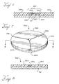
- FIG. 1 is a side view of a polishing pad of a first preferred embodiment.
- FIG. 2 is a side view of a portion of the polishing pad of FIG. 1.
- FIG. 3 is a side view of a portion of a polishing pad of a second preferred embodiment.
- FIG. 4 is a side view of a portion of a polishing pad of a third preferred embodiment.
- FIG. 5 is a side view of a portion of a polishing pad of a fourth preferred embodiment.
- FIG. 6 is top view of a portion of a polishing pad of a fifth preferred embodiment.
- FIG. 7 is a side view of a portion of the polishing pad of FIG. 6.
- FIG. 8 is a flow chart of a method of joining polishing pad portions of a first preferred embodiment.
- the preferred embodiments described below include a method of joining two sections of polishing pad for use in a chemical mechanical planarization of a semiconductor wafer.
- the sections of polishing pad can be joined to make up a portion of a belt, while in another embodiment, the sections can be joined to make up a portion of a polishing pad for use in rotary-type polisher.
- the sections of polishing pad are arranged so that there is some contact between the sections.
- the two sections are welded together at the contacting areas to form a joint that resists slurry infiltration and is more robust than a common laminated joint.
- FIG. 1 depicts a stacked pad polishing belt 10 of a first embodiment.
- the stacked pad 10 comprises first, second, and third polishing pad sections 20, 22, 24 that are coupled with a steel belt 30.
- the phrase "coupled with,” as used herein, means coupled either directly or indirectly via one or more intervening elements.
- the first and second polishing pad sections 20, 22 are welded together to form a first joint 32.
- the second and third polishing pad sections 22, 24 are welded together to form a second joint 34.
- the first and third polishing pad sections 20, 24 are welded together to form a third joint 36.
- Each of the polishing pad sections 20, 22, 24 can comprise one or more portions of a polishing material and/or one or more portions of a cushioning material. Also, while a pad having three sections is depicted, a pad can have more or less than three sections.
- first and second cushioning pad portions 40, 42 are coupled with the steel belt 30.
- the first and second cushioning pad portions 40, 42 preferably comprise a polyurethane felt material such as the 817 pad available from Thomas West.
- the cushioning pad portions 40, 42 typically include a laminate or glue on both the top and bottom surfaces. This enables the bottom surfaces of the cushioning pads 40, 42 to be easily coupled with the steel belt 30 and also enables another pad to be easily coupled with the top surfaces of cushioning pads 40, 42.
- the cushioning pad portions 40, 42 are coupled with the steel belt through the use of the standard glue included on the pads.
- an additional or a different glue or laminate can be used with or substituted in place of the standard glue.
- the cushioning pad portions 40, 42 are arranged so that a first polishing pad portion 44 is positioned between the cushioning pad portions 40, 42.
- the first polishing pad portion 44 is coupled with the steel belt 30 and the second and third polishing pad portions 46, 48 are coupled with the first polishing pad portion 44 and the first cushioning pad portion 40 and the second cushioning pad portion 42, respectively.
- the polishing pad portions 44, 46, 48 preferably comprise a polyurethane based material such as IC 1000 available from Rodel. Alternatively the polishing pad portions 44, 46, 48 can comprise any suitable polishing pad materials.
- the polishing pad portions 44, 46, 48 typically include a glue or laminate on the back side that is used to attach the polishing pad portions 44, 46, 48 to a supporting structure, such as a steel belt, or to another pad. In this embodiment, the standard glue is used to couple the first polishing pad portion 44 with the steel belt 30.
- the first polishing pad portion 44 is preferably positioned between the first and second cushioning pad portions 40, 42 such that a maximum of a 0.03 inch gap exists between the first polishing pad portion 44 and the first and second cushioning pad portions 40, 42.
- the gap between the first polishing pad portion 44 and the first and second cushioning pad portions 40, 42 can also be greater or less than 0.03 inches.
- the second polishing pad portion 46 is coupled with the first cushioning pad portion 40 and the first polishing pad portion 44.
- the standard glue is used to attach a part of the second polishing pad portion 46 to the first cushioning pad portion 40.
- the standard glue is removed from the part of the second polishing pad portion 44 that is coupled with the first polishing pad portion 44.
- the second polishing pad portion 46 is welded to the first polishing pad portion 44, as described in more detail below, to form a weld 50.
- the third polishing pad portion 48 is attached to the second cushioning pad portion 42 and the first polishing pad portion 44.
- the standard glue is used to couple a part of the third polishing pad portion 48 to the second cushioning pad portion 42.
- the standard glue is removed from the part of the third polishing pad portion 48 that is coupled with the first polishing pad portion 44.
- the third polishing pad portion 48 is welded to the first polishing pad portion 44, to form a weld 52.
- the second and third polishing pad portions 46, 48 are preferably positioned so that a gap is formed between the two portions. This gap is preferably between 0.12 and 0.25 inches wide.
- the second and third polishing pad portions 46, 48 are preferably welded to the first polishing pad portion 44 by ultrasonic welding.
- high-frequency electrical energy is converted into high-frequency mechanical motion.
- the mechanical motion is transmitted to the pieces in the form of vibrations.
- the combination of the vibrations and applied force creates frictional heat at the mating surfaces of the pieces. This head causes the plastic material to melt thereby forming a molecular bond between the parts.
- the portions 44, 46, 48 Before the polishing pad portions 44, 46, 48 can be welded together, the portions must be prepared for the welding process.
- the standard glue that is included on the backside of the portions must be removed from the sections of the second and third polishing pad portions 46, 48 that will be attached to the first polishing pad portion 44 (act 110, FIG. 3).
- the second polishing pad portion 46 is placed on top of both the first cushioning pad portion 40, and the first polishing pad portion 44 (act 120).
- the second polishing pad portion 46 should be positioned so that the section without the glue on the backside overlaps the first polishing pad portion 44.
- the overlapping sections of the first and second polishing pad portions 44, 46 are placed in a support fixture (act 130).
- a horn which is typically made from stainless steel or the like, is brought into contact with the top surface of the second polishing pad portion 46 (act 140).
- a controlled pressure is applied to the second polishing pad portion 46 (act 150), thereby clamping it and the first polishing pad portion 44 together against the fixture.
- the horn is vibrated vertically for a predetermined amount of time (act 160). This time period is called the weld time. During the welding time, the horn moves in increments of thousandths of an inch (microns). The distance the horn moves is called the collapse distance.
- the frequency of the vibrations is preferably 20,000 cycles per second (20 kHz). However, the frequency can vary depending upon the material being welded and the type of weld desired.
- the mechanical vibrations are transmitted through the first and second polishing pad portions 44, 46 creating frictional heat between the portions at the points where the two sections meet.
- the material melts and flows.
- the vibration is stopped at this time (act 170).
- the clamping force is maintained for a predetermined amount of time after the vibrations have stopped (act 180) to allow the parts to fuse as the melted material cools and solidifies. This period of time is known as the hold time.
- the clamping force is removed (act 190) and the horn is retracted.
- the two polishing pad portions 44, 46 are joined by a weld and can be removed from the fixture as one part.
- This process can be repeated multiple times to created additional welds between the first and second polishing pad portions 44, 46.
- the entire process can also be repeated to weld the first and third polishing pad portions 44, 48 together with one or more welds.
- One suitable ultrasonic machine for welding the polishing pad portions 44, 46, 48 is the Branson Model 920IW.
- the air pressure should be set between 65 and 70 psi, the collapse mode should be set at 0.033", the hold time should be 2 seconds, and the trigger pressure should be set at 2.5 pounds.
- Inertia welding utilizes kinetic energy of a flywheel that is converted to heat energy by friction between the sections. One section is fixed while the other is clamped in a spindle chuck. The flywheel to which the movable part is attached is accelerated and at a predetermined speed, driving power is cut and the two parts are forced together. Fusion welding involves plasticizing or melting the edges of the pieces being welded by placing them in contact with a heating platen. Once the edges are plasticized and a proper melt depth is reached, the heating platen is removed and the two edges are forced together. As the parts cool, the edges are welded together.
- Hot gas welding involves heating the pieces to be joined and a thermoplastic rod through the use of an inert gas.
- the heat source is removed and the parts are held in place while they cool.
- the pieces are welded together.
- Induction welding involves pressing the pieces that are to be welded together around a metal insert.
- the pieces and the metal are then passed through a magnetic field.
- the metal is heated and the pressure produces a fusion weld.
- the metal remains sealed inside the parts.
- Dielectric welding involves breaking down the plastic under high voltages and frequencies that produce heating. The heating causes the plastic to melt and the parts are welded together.
- Solvent welding involves coating the pieces that are to be welding with a solvent that softens them. When they are soft enough, the pieces are forced together. The plastic molecules from the two parts mix together and, as the solvent evaporates, the parts are welded together.
- first and second polishing pad portions 204, 206 are coupled with a steel belt 30.
- the ends 205, 207 of the first and second polishing pad portions 204, 206 are butted against each other.
- the butted ends 205, 207 are welded together to form a weld 208. Any of the above methods of welding can be used to weld the two portions together.
- first and second polishing pad portions 214, 216 are coupled with a steel belt 30.
- the first and second polishing pad portions 214, 216 are fashioned such that a tongue 215, 217 extends outwardly from the end of both the first and second polishing pad portions 214, 216.
- the tongues 215, 217 overlap each other and are welded together to form a weld 218. Any of the above methods of welding can be used to weld the two portions together.
- first and second polishing pad portions 224, 226 are coupled with a steel belt 30.
- a filler portion 228 is coupled with the steel belt 30 and is positioned between the first and second polishing pad portions 224, 226.
- the filler portion 228 preferably comprises the same material as the polishing pad portions 224, 226, but can comprise any suitable material.
- the first and second polishing pad portions 224, 226 are fashioned such that a tongue 225, 227 extends outwardly from the end of both the first and second polishing pad portions a 224, 226.
- the tongues 225, 227 each overlap the filler portion 228 and are welded to the filler portion 228 to form welds 230, 232. Any of the above methods of welding can be used to weld the two portions together.
- the polishing pad 300 first, second, and third polishing pad sections 320, 322, 324 that are coupled with a rotary table 330.
- the first and second polishing pad sections 320, 322 are welded together to form a first joint 332.
- the second and third polishing pad sections 322, 324 are welded together to form a second joint 334.
- the first and third polishing pad sections 320, 324 are welded together to form a third joint 336.
- Each of the polishing pad sections 320, 322, 324 can comprise portions of a polishing pad and can also comprise portions of a cushioning pad as described below.
- polishing pad 300 is depicted as having three sections, more or less than three sections can be used in the pad. Any of the configurations depicted above in FIGS. 2 and 4-6 can be used to join the sections. Also, any of the above methods of welding can be used to weld the two portions together.
- the resulting portion of the polishing pad includes welded joints that are resistant to slurry infiltration and is more robust than a standard laminated joint. Accordingly the life of the polishing pad is increased.
Landscapes
- Engineering & Computer Science (AREA)
- Mechanical Engineering (AREA)
- Finish Polishing, Edge Sharpening, And Grinding By Specific Grinding Devices (AREA)
- Mechanical Treatment Of Semiconductor (AREA)
Applications Claiming Priority (2)
| Application Number | Priority Date | Filing Date | Title |
|---|---|---|---|
| US476459 | 1999-12-30 | ||
| US09/476,459 US6569004B1 (en) | 1999-12-30 | 1999-12-30 | Polishing pad and method of manufacture |
Publications (2)
| Publication Number | Publication Date |
|---|---|
| EP1112816A2 true EP1112816A2 (fr) | 2001-07-04 |
| EP1112816A3 EP1112816A3 (fr) | 2001-10-04 |
Family
ID=23891937
Family Applications (1)
| Application Number | Title | Priority Date | Filing Date |
|---|---|---|---|
| EP00311271A Withdrawn EP1112816A3 (fr) | 1999-12-30 | 2000-12-15 | Tampon de polissage et procédé de fabrication |
Country Status (4)
| Country | Link |
|---|---|
| US (2) | US6569004B1 (fr) |
| EP (1) | EP1112816A3 (fr) |
| JP (1) | JP2001274120A (fr) |
| TW (1) | TW476692B (fr) |
Cited By (3)
| Publication number | Priority date | Publication date | Assignee | Title |
|---|---|---|---|---|
| US6997777B2 (en) | 2003-06-17 | 2006-02-14 | Cabot Microelectronics Corporation | Ultrasonic welding method for the manufacture of a polishing pad comprising an optically transmissive region |
| WO2006003524A3 (fr) * | 2004-06-30 | 2006-06-15 | Ideepak Holding Bv | Dispositif d'etancheite destine a un materiau d'etancheite en forme de film et courroie de circulation conçue pour faire avancer le materiau en forme de film |
| CN115397614A (zh) * | 2020-03-26 | 2022-11-25 | 富士纺控股株式会社 | 抛光垫、抛光单元、抛光装置、及抛光垫的制造方法 |
Families Citing this family (45)
| Publication number | Priority date | Publication date | Assignee | Title |
|---|---|---|---|---|
| US6569004B1 (en) * | 1999-12-30 | 2003-05-27 | Lam Research | Polishing pad and method of manufacture |
| US6962524B2 (en) * | 2000-02-17 | 2005-11-08 | Applied Materials, Inc. | Conductive polishing article for electrochemical mechanical polishing |
| US7678245B2 (en) * | 2000-02-17 | 2010-03-16 | Applied Materials, Inc. | Method and apparatus for electrochemical mechanical processing |
| US7125477B2 (en) * | 2000-02-17 | 2006-10-24 | Applied Materials, Inc. | Contacts for electrochemical processing |
| US7670468B2 (en) * | 2000-02-17 | 2010-03-02 | Applied Materials, Inc. | Contact assembly and method for electrochemical mechanical processing |
| US7303462B2 (en) * | 2000-02-17 | 2007-12-04 | Applied Materials, Inc. | Edge bead removal by an electro polishing process |
| US7077721B2 (en) | 2000-02-17 | 2006-07-18 | Applied Materials, Inc. | Pad assembly for electrochemical mechanical processing |
| US20030213703A1 (en) * | 2002-05-16 | 2003-11-20 | Applied Materials, Inc. | Method and apparatus for substrate polishing |
| US6991528B2 (en) * | 2000-02-17 | 2006-01-31 | Applied Materials, Inc. | Conductive polishing article for electrochemical mechanical polishing |
| US7374644B2 (en) | 2000-02-17 | 2008-05-20 | Applied Materials, Inc. | Conductive polishing article for electrochemical mechanical polishing |
| US20050092621A1 (en) * | 2000-02-17 | 2005-05-05 | Yongqi Hu | Composite pad assembly for electrochemical mechanical processing (ECMP) |
| US6884153B2 (en) * | 2000-02-17 | 2005-04-26 | Applied Materials, Inc. | Apparatus for electrochemical processing |
| US7029365B2 (en) * | 2000-02-17 | 2006-04-18 | Applied Materials Inc. | Pad assembly for electrochemical mechanical processing |
| US7066800B2 (en) * | 2000-02-17 | 2006-06-27 | Applied Materials Inc. | Conductive polishing article for electrochemical mechanical polishing |
| US7059948B2 (en) * | 2000-12-22 | 2006-06-13 | Applied Materials | Articles for polishing semiconductor substrates |
| US7303662B2 (en) * | 2000-02-17 | 2007-12-04 | Applied Materials, Inc. | Contacts for electrochemical processing |
| US20040020789A1 (en) * | 2000-02-17 | 2004-02-05 | Applied Materials, Inc. | Conductive polishing article for electrochemical mechanical polishing |
| US6979248B2 (en) * | 2002-05-07 | 2005-12-27 | Applied Materials, Inc. | Conductive polishing article for electrochemical mechanical polishing |
| US6896776B2 (en) * | 2000-12-18 | 2005-05-24 | Applied Materials Inc. | Method and apparatus for electro-chemical processing |
| US7137879B2 (en) * | 2001-04-24 | 2006-11-21 | Applied Materials, Inc. | Conductive polishing article for electrochemical mechanical polishing |
| US7344432B2 (en) | 2001-04-24 | 2008-03-18 | Applied Materials, Inc. | Conductive pad with ion exchange membrane for electrochemical mechanical polishing |
| US20030072639A1 (en) * | 2001-10-17 | 2003-04-17 | Applied Materials, Inc. | Substrate support |
| US20050194681A1 (en) * | 2002-05-07 | 2005-09-08 | Yongqi Hu | Conductive pad with high abrasion |
| EP1594656B1 (fr) | 2003-02-18 | 2007-09-12 | Parker-Hannifin Corporation | Article de polissage pour polissage mecanique electrochimique |
| JP4676135B2 (ja) * | 2003-04-30 | 2011-04-27 | ニッタ・ハース株式会社 | 研磨パッド片の取付け構造および研磨装置 |
| US8066552B2 (en) * | 2003-10-03 | 2011-11-29 | Applied Materials, Inc. | Multi-layer polishing pad for low-pressure polishing |
| US20050173259A1 (en) * | 2004-02-06 | 2005-08-11 | Applied Materials, Inc. | Endpoint system for electro-chemical mechanical polishing |
| US7186164B2 (en) * | 2003-12-03 | 2007-03-06 | Applied Materials, Inc. | Processing pad assembly with zone control |
| US20050178666A1 (en) * | 2004-01-13 | 2005-08-18 | Applied Materials, Inc. | Methods for fabrication of a polishing article |
| US20060030156A1 (en) * | 2004-08-05 | 2006-02-09 | Applied Materials, Inc. | Abrasive conductive polishing article for electrochemical mechanical polishing |
| US7084064B2 (en) | 2004-09-14 | 2006-08-01 | Applied Materials, Inc. | Full sequence metal and barrier layer electrochemical mechanical processing |
| WO2006039436A2 (fr) * | 2004-10-01 | 2006-04-13 | Applied Materials, Inc. | Modele de tampon pour polissage electrochimique mecanique |
| US7520968B2 (en) * | 2004-10-05 | 2009-04-21 | Applied Materials, Inc. | Conductive pad design modification for better wafer-pad contact |
| US8317490B2 (en) * | 2005-03-08 | 2012-11-27 | Ldg Enterprises, Llc | Torque drive mechanism for gas compressor |
| WO2006096845A2 (fr) * | 2005-03-08 | 2006-09-14 | Manning John B | Dispositif de demarrage de moteur electrique |
| US7427340B2 (en) * | 2005-04-08 | 2008-09-23 | Applied Materials, Inc. | Conductive pad |
| JP2007329342A (ja) * | 2006-06-08 | 2007-12-20 | Toshiba Corp | 化学的機械的研磨方法 |
| US20080293343A1 (en) * | 2007-05-22 | 2008-11-27 | Yuchun Wang | Pad with shallow cells for electrochemical mechanical processing |
| US20080295947A1 (en) * | 2007-06-01 | 2008-12-04 | Bourbeau Alain | Method for ultrasonic welding and ultrasonic welding fastener and joining systems |
| JP5567373B2 (ja) * | 2010-03-31 | 2014-08-06 | 富士紡ホールディングス株式会社 | 保持材および保持材の製造方法 |
| US20110287698A1 (en) * | 2010-05-18 | 2011-11-24 | Hitachi Global Storage Technologies Netherlands B.V. | System, method and apparatus for elastomer pad for fabricating magnetic recording disks |
| US8360823B2 (en) * | 2010-06-15 | 2013-01-29 | 3M Innovative Properties Company | Splicing technique for fixed abrasives used in chemical mechanical planarization |
| JP7083848B2 (ja) | 2017-02-22 | 2022-06-13 | エーシーエス インダストリーズ、インク. | セグメント化された回転式フロア用剥離パッド |
| WO2020110258A1 (fr) * | 2018-11-29 | 2020-06-04 | 株式会社大輝 | Tampon de polissage et son procédé de fabrication |
| CN114957965A (zh) * | 2022-07-07 | 2022-08-30 | 福建长泰万泰矿物制品有限公司 | 一种高耐热聚氨酯组合物、聚氨酯盘及其制备方法 |
Family Cites Families (23)
| Publication number | Priority date | Publication date | Assignee | Title |
|---|---|---|---|---|
| DE247169C (fr) | ||||
| US3074789A (en) | 1959-02-16 | 1963-01-22 | Minnesota Mining & Mfg | Method of splicing coated flexible films and product thereof |
| US3306718A (en) | 1964-03-16 | 1967-02-28 | Du Pont | Abrasive product |
| US4177100A (en) | 1976-12-13 | 1979-12-04 | William Pennington | Plastic sheet sealing process and apparatus |
| DE3526502A1 (de) | 1985-07-24 | 1987-01-29 | Norddeutsche Schleifmittel Ind | Schleifband mit einer quer zu seiner laengsrichtung verlaufenden verbindungsfuge |
| US4725567A (en) * | 1985-12-02 | 1988-02-16 | General Electric Company | Composite by infiltration |
| DD247169A1 (de) * | 1986-03-05 | 1987-07-01 | Inst Fuer Nachrichtentechnik | Verfahren zum herstellen von endlosen schleifbaendern |
| US4724567A (en) | 1986-07-09 | 1988-02-16 | Americo Manufacturing Company, Inc. | Polishing and scrubbing pad |
| DE8704435U1 (de) | 1987-03-25 | 1987-05-21 | Carborundum Schleifmittelwerke GmbH, 4000 Düsseldorf | Schleifband |
| GB9020462D0 (en) * | 1990-09-19 | 1990-10-31 | Filters For Industry Ltd | Abrasive segments |
| US5200610A (en) * | 1990-09-21 | 1993-04-06 | The United States Of America As Represented By The Administrator Of The National Aeronautics And Space Administration | Fiber optic microphone having a pressure sensing reflective membrane and a voltage source for calibration purpose |
| US6406576B1 (en) * | 1991-12-20 | 2002-06-18 | 3M Innovative Properties Company | Method of making coated abrasive belt with an endless, seamless backing |
| US5593344A (en) * | 1994-10-11 | 1997-01-14 | Ontrak Systems, Inc. | Wafer polishing machine with fluid bearings and drive systems |
| US5575707A (en) * | 1994-10-11 | 1996-11-19 | Ontrak Systems, Inc. | Polishing pad cluster for polishing a semiconductor wafer |
| JPH0957608A (ja) * | 1995-08-11 | 1997-03-04 | Sony Corp | 研磨パッド及びこれを用いた被表面処理加工物の研磨方法 |
| JP3029241B2 (ja) * | 1995-10-12 | 2000-04-04 | カワベ工業株式会社 | 研摩シート |
| US6328642B1 (en) * | 1997-02-14 | 2001-12-11 | Lam Research Corporation | Integrated pad and belt for chemical mechanical polishing |
| US5993298A (en) | 1997-03-06 | 1999-11-30 | Keltech Engineering | Lapping apparatus and process with controlled liquid flow across the lapping surface |
| US6108091A (en) | 1997-05-28 | 2000-08-22 | Lam Research Corporation | Method and apparatus for in-situ monitoring of thickness during chemical-mechanical polishing |
| JPH11333703A (ja) * | 1998-05-28 | 1999-12-07 | Speedfam-Ipec Co Ltd | ポリッシング加工機 |
| US6000997A (en) * | 1998-07-10 | 1999-12-14 | Aplex, Inc. | Temperature regulation in a CMP process |
| JP2918883B1 (ja) * | 1998-07-15 | 1999-07-12 | 日本ピラー工業株式会社 | 研磨パッド |
| US6569004B1 (en) * | 1999-12-30 | 2003-05-27 | Lam Research | Polishing pad and method of manufacture |
-
1999
- 1999-12-30 US US09/476,459 patent/US6569004B1/en not_active Expired - Fee Related
-
2000
- 2000-12-15 EP EP00311271A patent/EP1112816A3/fr not_active Withdrawn
- 2000-12-28 JP JP2000405014A patent/JP2001274120A/ja active Pending
- 2000-12-29 TW TW089128331A patent/TW476692B/zh not_active IP Right Cessation
-
2003
- 2003-04-07 US US10/408,750 patent/US6869339B2/en not_active Expired - Fee Related
Cited By (3)
| Publication number | Priority date | Publication date | Assignee | Title |
|---|---|---|---|---|
| US6997777B2 (en) | 2003-06-17 | 2006-02-14 | Cabot Microelectronics Corporation | Ultrasonic welding method for the manufacture of a polishing pad comprising an optically transmissive region |
| WO2006003524A3 (fr) * | 2004-06-30 | 2006-06-15 | Ideepak Holding Bv | Dispositif d'etancheite destine a un materiau d'etancheite en forme de film et courroie de circulation conçue pour faire avancer le materiau en forme de film |
| CN115397614A (zh) * | 2020-03-26 | 2022-11-25 | 富士纺控股株式会社 | 抛光垫、抛光单元、抛光装置、及抛光垫的制造方法 |
Also Published As
| Publication number | Publication date |
|---|---|
| US6569004B1 (en) | 2003-05-27 |
| TW476692B (en) | 2002-02-21 |
| US20040018805A1 (en) | 2004-01-29 |
| US6869339B2 (en) | 2005-03-22 |
| EP1112816A3 (fr) | 2001-10-04 |
| JP2001274120A (ja) | 2001-10-05 |
Similar Documents
| Publication | Publication Date | Title |
|---|---|---|
| US6569004B1 (en) | Polishing pad and method of manufacture | |
| JP5017358B2 (ja) | ポリマー複合部材への機能部材の溶着 | |
| JP3004413B2 (ja) | 熱可塑性樹脂ベルトの可変速度溶接 | |
| EP0281347B1 (fr) | Liaison de couches en matière plastique | |
| JPH05269849A (ja) | 可撓性画像形成用シート | |
| US6447866B1 (en) | Frictionally welded thermoplastic articles having improved strength | |
| JPH08113337A (ja) | 大きな強度を備えたエンドレス継合ベルト | |
| TW200948520A (en) | Combined device of ultrasonic welding and spin welding | |
| JP2004154790A (ja) | 摩擦攪拌接合装置とその接合方法 | |
| CA1339405C (fr) | Procede de thermofusion d'elements en plastique et d'elements compositesa matrice plastique | |
| JP3456921B2 (ja) | 金属箔の接合方法並びに超音波溶接具 | |
| JP3734847B2 (ja) | シール装置 | |
| JP7783168B2 (ja) | 前倒し振幅均等超音波溶接ホーンを備えるセルフレベリングスタック組立体 | |
| JP2010143156A (ja) | 超音波溶着法 | |
| US20070262488A1 (en) | Friction weld of two dissimilar materials | |
| TWI739818B (zh) | 對介電電路材料進行層壓之方法 | |
| JP2007007971A (ja) | 多孔質ユニット及びその製造方法 | |
| US6372066B1 (en) | Vibration exciter | |
| KR100804511B1 (ko) | 플라스틱 제품의 접합방법 | |
| JPH11268135A (ja) | 超音波接合方法 | |
| JPH11115055A (ja) | スピン溶着方法及びこの方法を実施する機構を備えたスピン溶着装置 | |
| KR101846929B1 (ko) | 초음파 융착방식으로 접합되는 moc 액츄에이터 | |
| KR100650026B1 (ko) | 초음파 접합장치 | |
| KR102879844B1 (ko) | 하이브리드 융착기 | |
| KR200412661Y1 (ko) | 초음파 접합장치의 공구혼 조립체 |
Legal Events
| Date | Code | Title | Description |
|---|---|---|---|
| PUAI | Public reference made under article 153(3) epc to a published international application that has entered the european phase |
Free format text: ORIGINAL CODE: 0009012 |
|
| AK | Designated contracting states |
Kind code of ref document: A2 Designated state(s): DE FR GB IT NL Kind code of ref document: A2 Designated state(s): AT BE CH CY DE DK ES FI FR GB GR IE IT LI LU MC NL PT SE TR |
|
| AX | Request for extension of the european patent |
Free format text: AL;LT;LV;MK;RO;SI |
|
| PUAL | Search report despatched |
Free format text: ORIGINAL CODE: 0009013 |
|
| AK | Designated contracting states |
Kind code of ref document: A3 Designated state(s): AT BE CH CY DE DK ES FI FR GB GR IE IT LI LU MC NL PT SE TR |
|
| AX | Request for extension of the european patent |
Free format text: AL;LT;LV;MK;RO;SI |
|
| 17P | Request for examination filed |
Effective date: 20020402 |
|
| AKX | Designation fees paid |
Free format text: DE FR GB IT NL |
|
| 17Q | First examination report despatched |
Effective date: 20030620 |
|
| STAA | Information on the status of an ep patent application or granted ep patent |
Free format text: STATUS: THE APPLICATION IS DEEMED TO BE WITHDRAWN |
|
| 18D | Application deemed to be withdrawn |
Effective date: 20080701 |