EP1112896A1 - Leistungerzeugungsystem für ein Doppelspannungsnetz - Google Patents
Leistungerzeugungsystem für ein Doppelspannungsnetz Download PDFInfo
- Publication number
- EP1112896A1 EP1112896A1 EP00403549A EP00403549A EP1112896A1 EP 1112896 A1 EP1112896 A1 EP 1112896A1 EP 00403549 A EP00403549 A EP 00403549A EP 00403549 A EP00403549 A EP 00403549A EP 1112896 A1 EP1112896 A1 EP 1112896A1
- Authority
- EP
- European Patent Office
- Prior art keywords
- voltage
- network
- sub
- alternator
- generation system
- Prior art date
- Legal status (The legal status is an assumption and is not a legal conclusion. Google has not performed a legal analysis and makes no representation as to the accuracy of the status listed.)
- Granted
Links
Images


Classifications
-
- H—ELECTRICITY
- H02—GENERATION; CONVERSION OR DISTRIBUTION OF ELECTRIC POWER
- H02J—ELECTRIC POWER NETWORKS; CIRCUIT ARRANGEMENTS OR SYSTEMS FOR SUPPLYING OR DISTRIBUTING ELECTRIC POWER; SYSTEMS FOR STORING ELECTRIC ENERGY
- H02J7/00—Circuit arrangements for charging or discharging batteries or for supplying loads from batteries
- H02J7/14—Circuit arrangements for charging or discharging batteries or for supplying loads from batteries for charging batteries from dynamo-electric generators driven at varying speed, e.g. on vehicle
- H02J7/1423—Circuit arrangements for charging or discharging batteries or for supplying loads from batteries for charging batteries from dynamo-electric generators driven at varying speed, e.g. on vehicle with multiple batteries
-
- B—PERFORMING OPERATIONS; TRANSPORTING
- B60—VEHICLES IN GENERAL
- B60R—VEHICLES, VEHICLE FITTINGS, OR VEHICLE PARTS, NOT OTHERWISE PROVIDED FOR
- B60R16/00—Electric or fluid circuits specially adapted for vehicles and not otherwise provided for; Arrangement of elements of electric or fluid circuits specially adapted for vehicles and not otherwise provided for
- B60R16/02—Electric or fluid circuits specially adapted for vehicles and not otherwise provided for; Arrangement of elements of electric or fluid circuits specially adapted for vehicles and not otherwise provided for electric constitutive elements
- B60R16/03—Electric or fluid circuits specially adapted for vehicles and not otherwise provided for; Arrangement of elements of electric or fluid circuits specially adapted for vehicles and not otherwise provided for electric constitutive elements for supply of electrical power to vehicle subsystems or for
-
- H—ELECTRICITY
- H02—GENERATION; CONVERSION OR DISTRIBUTION OF ELECTRIC POWER
- H02J—ELECTRIC POWER NETWORKS; CIRCUIT ARRANGEMENTS OR SYSTEMS FOR SUPPLYING OR DISTRIBUTING ELECTRIC POWER; SYSTEMS FOR STORING ELECTRIC ENERGY
- H02J2105/00—Networks for supplying or distributing electric power characterised by their spatial reach or by the load
- H02J2105/30—Networks for supplying or distributing electric power characterised by their spatial reach or by the load the load networks being external to vehicles, i.e. exchanging power with vehicles
- H02J2105/33—Networks for supplying or distributing electric power characterised by their spatial reach or by the load the load networks being external to vehicles, i.e. exchanging power with vehicles exchanging power with road vehicles
-
- Y—GENERAL TAGGING OF NEW TECHNOLOGICAL DEVELOPMENTS; GENERAL TAGGING OF CROSS-SECTIONAL TECHNOLOGIES SPANNING OVER SEVERAL SECTIONS OF THE IPC; TECHNICAL SUBJECTS COVERED BY FORMER USPC CROSS-REFERENCE ART COLLECTIONS [XRACs] AND DIGESTS
- Y02—TECHNOLOGIES OR APPLICATIONS FOR MITIGATION OR ADAPTATION AGAINST CLIMATE CHANGE
- Y02T—CLIMATE CHANGE MITIGATION TECHNOLOGIES RELATED TO TRANSPORTATION
- Y02T10/00—Road transport of goods or passengers
- Y02T10/60—Other road transportation technologies with climate change mitigation effect
- Y02T10/70—Energy storage systems for electromobility, e.g. batteries
Definitions
- the invention relates to a system for generating power for an on-board dual voltage electrical network on a motor vehicle, intended to meet the increasing demand for electrical power within future vehicles, which will present new electrical functions designed to improve safety, like passenger comfort. Simultaneously, the invention must take into account the objectives of increasingly reduced fuel consumption, also aimed at reducing pollutant emissions.
- one solution is to replace the diodes of the rectification circuit by transistors to constitute an inverter.
- Another solution currently being considered by automakers is to increase the output voltage, in particular to triple the voltage current from the 14 Volt network to reach 42 Volts.
- This solution is advantageous because it allows the use of certain consumers who do not work with 42 Volts, improving the network distribution both in terms of relaying, fusiblage, the connection as the cable section which is then reduced, and the production extra energy.
- This phase of cohabitation of the two sub-networks of different voltages suppose a configuration particular electrical production system of energy, an example of which is shown in the diagram functional of Figure 1. It comprises, driven by the vehicle engine 2 shaft, direct or via a reducer, an electrical machine 3, of the type alternator or alternator-starter, associated with a circuit rectification 4 made from one or more diode bridges according to the number of stator windings.
- an alternator-starter the rectification is carried out using transistors constituting a inverter.
- the machine thus straightened is connected by a share of elements 5 consumers in 42 Volts and on the other hand to a battery 6, which can be constituted of several storage elements 60, of tension between 30 and 48 Volts.
- a converter static 7 should lower the voltage from 42 Volts to one nominal voltage of 14 Volts, to ensure transfer of energy to the second network, which has a battery 8 of 12 Volts and powers the elements consumers 9 operating at this voltage.
- This architecture has many disadvantages, including the presence of this electronic converter, expensive, bulky - approximately 1.5 liters of volume depending on its power -, generating heat losses difficult to evacuate.
- the invention aims to overcome these drawbacks by offering an energy production system for dual voltage network without DC / DC voltage converter, can operate as alternator or alternator-starter and authorizing the transfer of energy from a from the two subnets to the other, in particular from 42 Volts around 14 Volts, but also so fully reversible.
- the object of the invention is a power generation system for a two-voltage electrical network, comprising an electrical machine of the three-phase alternator type whose stator phases are rectified to generate the desired power on the sub-network operating at a first voltage value U s , characterized in that the stator of the three-phase alternator is wound in a star so as to have a neutral point N to which the second sub-network operating is connected to a second voltage value U b less than the first, and in that it comprises electronic means for controlling and regulating the voltages U s and U b of the two sub-networks.
- the means for rectifying the stator phases of the three-phase alternator are constituted by a three-phase inverter comprising six switches H 1 to H 3 and L 1 to L 3 , of the type transistors, connected in series and in the same direction, in groups of two between earth and the highest voltage U s for each of the three phases of the stator, each of the six transistors being controlled by the electronic control circuit, which is intended in slaving the average value of the voltage of the three phases to a reference voltage making it possible to obtain the voltage U b at the input of the second lower voltage sub-network.
- the system further comprises two filtering means respectively arranged at the neutral point N at the input of the lower voltage sub-grid U b and at the output of the inverter at the input of the higher voltage sub-network U b s .
- the means for rectifying the stator phases of the three-phase alternator consist of a passive rectification bridge comprising six diodes d 1 to d 6 , mounted in groups of two, in series and in the same direction, between the ground and the highest voltage U s for each of the three phases of the stator and in that the electronic means for regulating the voltage U b of the second sub-network consist of a switch I 0 whose closure is controlled by a control circuit.
- the means for rectifying the stator phases of the three-phase alternator are constituted by a passive rectifying bridge comprising six diodes d 1 to d 6 , mounted in groups of two, in series and in the same direction, between the mass and the highest voltage U s for each of the three phases of the stator and in that the electronic means for regulating the voltage U b of the second sub-network are constituted by a linear or switching regulator.
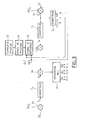
- the power production system for a two-voltage electrical network comprises a three-phase electrical machine 20 of the alternator type, which can be synchronous with a wound rotor or with magnets, or even mixed wound and with magnets.
- the stator phases are rectified to generate the desired power on the first sub-network operating at a first voltage value U s .
- U s can also be an asynchronous alternator. It is wound in a star to the stator so as to present a neutral point N to which is connected the second sub-network operating at a second voltage value U b lower than the first voltage value U s .
- a three-phase inverter 21 which delivers a voltage U s , equal to 42 Volts in the particular case of a current motor vehicle, and which consists of six switches H 1 to H 3 and L 1 to L 3 . They are arranged in three arms of two switches each, mounted in series and in the same direction, one L i "low-side” between the ground and one of the phases and the other H i "high-side” between the phase and the higher voltage U s .
- These switches are MOSFET or IGBT or bipolar or other type transistors, whether or not associated with a reverse diode.
- control and regulation means 22 which receive instructions for regulating the voltages U s and U b of the two sub-networks, coming from a computer 99 establishing electronic strategies for managing the electrical energy of the network.
- control means 22 can also receive information on the position of the rotor relative to the stator from a position sensor 32.
- Two filtering means 23 and 24 can be respectively arranged at the entrance of each of the two subnets, i.e. at neutral point N, towards the 14 Volt subnet and at the output S of the regulation circuit, to the 42 Volt sub-network.
- These means are for example made up of capacities associated with inductors dimensioned to deliver filtered DC voltages remaining within tolerances allowed for the application, electromagnetic emission and susceptibility.
- These two subnets can each have one battery, referenced respectively 25 and 26, and supply consumers 27 and 28 operating 14 Volts and 42 Volts respectively.
- Voltage regulation on the 14 Volt sub-network, is obtained by adjusting the average value of the three phase voltages, i.e. by adjusting the three control signals of the three-phase machine delivered by the electronic circuit for controlling and regulating the voltages U s and U b of the two-voltage network.
- alternator or alternator-starter.
- the regulation of these two voltages is done according to a method of pulse width modulation of control signals of the transistors constituting the arm of the inverter, to generate on the three phases, three periodic waves, sinusoidal, trapezoidal, triangular for example, out of phase with 120 ° from each other.
- This process is applicable to three types of machine: synchronous wound rotor (SYRB), synchronous permanent magnet (SYAP) and asynchronous (ASY).
- the regulation is done according to a command process "full wave" of the synchronous rectification type, applicable only to synchronous rotor machines coil.
- the regulation of the upper voltage U s is carried out by two parameters: the adjustment of the amplitude of the setpoints of phase and the adjustment either of the excitation of the rotor in the case of a synchronous alternator with wound rotor, or of the slip of speed existing between the speed of the stator rotary field and the mechanical speed of rotation of the rotor in the case of a asynchronous alternator, ie of the phase shift between the stator magnetic field and the rotor flux in the case of a synchronous permanent magnet alternator.
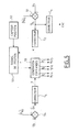
- FIG. 3 is a functional diagram of the electronic control means 22 of the inverter, ensuring the regulation of the two voltages U s and U b of the two-voltage network according to the invention.
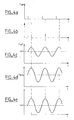
- means 33 generate the position signal, for example in the form of synchronization tops (FIG. 4 a ) which are sent to means 34 for developing a reference signal S ref , a sinusoid for example.
- These means 34 take into account the phase shift setpoints DEP or slip GLI, coming from the second corrector C 2 , to offset the synchronization tops of the position signal (FIG. 4b) from which the reference sinusoid S ref (FIG. 4 c ). To this is then applied a multiplicative coefficient C m , calculated by the correction circuit C 1 , to adjust the amplitude A of this sinusoid (FIG. 4 d ). This amplitude is imperatively less than U s , or 42 Volts, for reasons of safety of the passengers of the vehicle, so that its average is around 24 Volts.
- the lowest voltage U b is regulated by adjusting the average value of the setpoints of the three phases.
- This phase setpoint signal thus obtained is then transformed by a pulse width modulation method in means 37 for generating control pulses of the six transistors of the inverter 21, H i and L i , i varying from 1 to 3 ( Figure 4 f ).
- This control of the transistors of the inverter thus makes it possible to generate three periodic voltage waves, offset by 120 ° from one another, in the form of sinusoids in FIG. 4 g , at the level of the three phases P 1 to P 3 , authorizing continuous rotation of the alternator stator field.
- FIG. 5 a functional diagram of the electronic means of control of the inverter is shown in FIG. 5, in the case of a synchronous machine with a wound rotor, the regulation of the two voltages of the dual voltage network made by a "full wave” type control process synchronous rectification.
- Regulation of the upper voltage U s at the output of the inverter is carried out by two parameters: the adjustment of the excitation of the rotor on the one hand and the combined adjustment of the phase shift angle ⁇ and the angle of ⁇ opening of the inverter control signal pulses.
- differentiating means 51 calculate an error ⁇ s existing between the voltage U s measured at the input of the 42 Volt sub-network and a set value (U ' s ) c delivered by an external electronic computer, then send it to the first correcting means C 4 which will calculate the excitation EXC of the rotor.
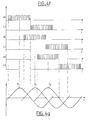
- a rotor position sensor 52 relative to the stator or an auto-detection method according to the type of synchronous machine make it possible to develop a position signal, for example in the form of synchronization ticks (FIG. 6 a ) , in means 53, which will be offset by a phase shift angle ⁇ (FIG. 6 b ), calculated in second correcting means C 5 from the error ⁇ s previously found.
- Second differentiating means 54 calculate the error ⁇ b between the voltage U b measured at the terminals of the second sub-network and a set value (U ' b ) c delivered by the external computer.
- This error ⁇ b passes through correcting means C 6 which calculate the opening angle ⁇ , sent into means 55 for generating control pulses of the inverter, which moreover receive the synchronization tops offset by the angle ⁇ .
- FIG. 6 c represents the control signals in each of the six transistors of the inverter, each pair of high H i and low L i transistors being assigned to one of the three phases P i , i varying from 1 to 3, at the output of which three periodic voltage waves are generated, offset by 120 °.
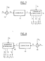
- Figure 7 is a block diagram of a structure voltage drop 42 Volts to voltage 14 Volts.
- the three arms of the inverter 21 are controlled at the same switching frequency and can be out of phase in order to decrease the residual rejection voltage on the two voltage networks.
- control means 22 of the inverter 21 comprise means 70 for generating control pulses of the transistors which receive, as input information, on the one hand the measured voltage U s at the terminals of the battery 26 of the first sub-network at 42 Volts and on the other hand the setpoint C calculated by correcting means 71 from the error ⁇ b resulting from the comparison between the measured voltage U b across the second sub-network and a reference value U b1 , carried out in comparison means 72.
- FIG. 8 is a block diagram of a static step-up converter.
- it is the voltage U b delivered by the battery 25 which is the input data from which the input voltage U s of the 42 Volt network will be regulated.
- This voltage U s is measured and compared in comparison means 80, to be controlled by a set point U C2 by determining a set point C 'in correcting means 81 from the error ⁇ s resulting from the comparison, in pulse width modulation.
- means 82 for generating control pulses send signals to the six transistors of the inverter 21.
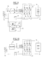
- the means for rectifying the stator phases of the three-phase alternator 90 are of the passive type, consisting of a bridge 91 of six diodes d 1 to d 6 , or three groups of two diodes connected in series and in the same direction, for each of the three phases of the alternator, between the ground and the highest voltage U s of the two-voltage network, ie 42 Volts in the example chosen.
- the voltage U s of the sub-network connected at the output of this passive rectification bridge is regulated only by controlling the excitation of the rotor R of the alternator.
- the electronic means for regulating the voltage U b of the second sub-network are constituted by a switch I 0 , the closing of which is controlled by a control circuit 92.
- This circuit 92 compares the measured voltage U b on the one hand to a first threshold S OFF , in a comparator 93, to deliver a signal for controlling the opening of the switch I o , and on the other hand, to a second threshold S ON , in another comparator 94, to deliver a command signal to close it.
- These two control signals will alternately drive the switch I o , after passing through a logic flip-flop 95.
- a diode 96 can be placed in series with the switch I o to improve its operation and avoid the passage of a current from the sub-network at 14 Volts to the sub-network at 42 Volts.
- the regulation of the voltage U b of the second sub-network is ensured by a regulator 97, either of the linear type if the voltage at the neutral point N is close to the voltage U b at the input of the sub-network, either of the switching type if the voltage at the neutral point N is close to half of the voltage U s at the terminals of the first sub-network.
- the fact that the alternator produces energy directly at the 14 Volt subnet without intermediary allows obtaining a very good yield.
- the system is completely reversible, allowing the energy transfer from one of the two subnets towards the other. Thanks to the independence of the values of regulation of the two subnets it is possible to apply the invention to other voltage values, different from 14 and 42 Volts.
- the system according to the invention makes compatible the production of electrical energy with the use of all types of storage, such as a battery lead, lithium, nickel-cadmium or a high value capacitor for example.
- the system is reliable and has a duration of increased life due to minimization of components used to produce energy electric to the dual voltage network.
Landscapes
- Engineering & Computer Science (AREA)
- Power Engineering (AREA)
- Control Of Eletrric Generators (AREA)
Applications Claiming Priority (2)
| Application Number | Priority Date | Filing Date | Title |
|---|---|---|---|
| FR9916750 | 1999-12-30 | ||
| FR9916750A FR2803447B1 (fr) | 1999-12-30 | 1999-12-30 | Systeme de generation de puissance pour un reseau bitension |
Publications (2)
| Publication Number | Publication Date |
|---|---|
| EP1112896A1 true EP1112896A1 (de) | 2001-07-04 |
| EP1112896B1 EP1112896B1 (de) | 2005-09-07 |
Family
ID=9554061
Family Applications (1)
| Application Number | Title | Priority Date | Filing Date |
|---|---|---|---|
| EP00403549A Expired - Lifetime EP1112896B1 (de) | 1999-12-30 | 2000-12-15 | Leistungerzeugungsystem für ein Doppelspannungsnetz |
Country Status (3)
| Country | Link |
|---|---|
| EP (1) | EP1112896B1 (de) |
| DE (1) | DE60022460T2 (de) |
| FR (1) | FR2803447B1 (de) |
Cited By (7)
| Publication number | Priority date | Publication date | Assignee | Title |
|---|---|---|---|---|
| WO2006105840A1 (de) * | 2005-04-06 | 2006-10-12 | Bayerische Motoren Werke Aktiengesellschaft | Schalteinrichtung zur verknüpfung verschiedener elektrischer spannungsebenen in einem kraftfahrzeug |
| FR3056037A1 (fr) * | 2016-09-14 | 2018-03-16 | Valeo Equipements Electriques Moteur | Systeme de transfert de puissance electrique |
| EP3434508A1 (de) * | 2017-07-25 | 2019-01-30 | Hamilton Sundstrand Corporation | Elektrische systemarchitektur für bereichserweiterte elektrische fahrzeuge |
| US10408191B2 (en) | 2016-03-21 | 2019-09-10 | General Electric Company | Wind pitch adjustment system |
| EP3842283A4 (de) * | 2019-01-15 | 2021-11-03 | LG Chem, Ltd. | Batterieladesystem und batterieladeverfahren |
| CN113746191A (zh) * | 2021-09-24 | 2021-12-03 | 中国北方车辆研究所 | 一种采用永磁电机构建直流±28v电源的方法 |
| EP4015297A4 (de) * | 2019-08-15 | 2022-10-19 | BYD Company Limited | Energieumwandlungsvorrichtung und fahrzeug |
Families Citing this family (2)
| Publication number | Priority date | Publication date | Assignee | Title |
|---|---|---|---|---|
| FR2933549B1 (fr) | 2008-07-02 | 2010-08-20 | Valeo Equip Electr Moteur | Procede pour commander une machine electrique tournante, notamment un alternateur |
| DE102010023732A1 (de) * | 2010-06-14 | 2011-12-15 | Audi Ag | Schaltungsanordnung, Kraftfahrzeug und Verfahren |
Citations (2)
| Publication number | Priority date | Publication date | Assignee | Title |
|---|---|---|---|---|
| US4239978A (en) * | 1978-03-09 | 1980-12-16 | Robert Bosch Gmbh | Method and system to supply electrical energy to a self-contained electrical network at multiple voltage level, multiple power range, particularly for mobile application |
| DE4226311A1 (de) * | 1992-08-08 | 1994-02-10 | Audi Ag | Drehstromgenerator |
-
1999
- 1999-12-30 FR FR9916750A patent/FR2803447B1/fr not_active Expired - Fee Related
-
2000
- 2000-12-15 DE DE60022460T patent/DE60022460T2/de not_active Expired - Lifetime
- 2000-12-15 EP EP00403549A patent/EP1112896B1/de not_active Expired - Lifetime
Patent Citations (2)
| Publication number | Priority date | Publication date | Assignee | Title |
|---|---|---|---|---|
| US4239978A (en) * | 1978-03-09 | 1980-12-16 | Robert Bosch Gmbh | Method and system to supply electrical energy to a self-contained electrical network at multiple voltage level, multiple power range, particularly for mobile application |
| DE4226311A1 (de) * | 1992-08-08 | 1994-02-10 | Audi Ag | Drehstromgenerator |
Cited By (12)
| Publication number | Priority date | Publication date | Assignee | Title |
|---|---|---|---|---|
| WO2006105840A1 (de) * | 2005-04-06 | 2006-10-12 | Bayerische Motoren Werke Aktiengesellschaft | Schalteinrichtung zur verknüpfung verschiedener elektrischer spannungsebenen in einem kraftfahrzeug |
| US10408191B2 (en) | 2016-03-21 | 2019-09-10 | General Electric Company | Wind pitch adjustment system |
| FR3056037A1 (fr) * | 2016-09-14 | 2018-03-16 | Valeo Equipements Electriques Moteur | Systeme de transfert de puissance electrique |
| WO2018051013A1 (fr) * | 2016-09-14 | 2018-03-22 | Valeo Equipements Electriques Moteur | Systeme de transfert de puissance electrique |
| EP3434508A1 (de) * | 2017-07-25 | 2019-01-30 | Hamilton Sundstrand Corporation | Elektrische systemarchitektur für bereichserweiterte elektrische fahrzeuge |
| EP3842283A4 (de) * | 2019-01-15 | 2021-11-03 | LG Chem, Ltd. | Batterieladesystem und batterieladeverfahren |
| JP2021536213A (ja) * | 2019-01-15 | 2021-12-23 | エルジー・ケム・リミテッド | バッテリー充電システムおよびバッテリー充電方法 |
| JP7199631B2 (ja) | 2019-01-15 | 2023-01-06 | エルジー エナジー ソリューション リミテッド | バッテリー充電システムおよびバッテリー充電方法 |
| US11981219B2 (en) | 2019-01-15 | 2024-05-14 | Lg Energy Solution, Ltd. | Battery charging system and battery charging method |
| EP4015297A4 (de) * | 2019-08-15 | 2022-10-19 | BYD Company Limited | Energieumwandlungsvorrichtung und fahrzeug |
| US11801764B2 (en) | 2019-08-15 | 2023-10-31 | Byd Company Limited | Energy conversion device and vehicle |
| CN113746191A (zh) * | 2021-09-24 | 2021-12-03 | 中国北方车辆研究所 | 一种采用永磁电机构建直流±28v电源的方法 |
Also Published As
| Publication number | Publication date |
|---|---|
| DE60022460D1 (de) | 2005-10-13 |
| FR2803447A1 (fr) | 2001-07-06 |
| FR2803447B1 (fr) | 2003-08-29 |
| EP1112896B1 (de) | 2005-09-07 |
| DE60022460T2 (de) | 2006-06-14 |
Similar Documents
| Publication | Publication Date | Title |
|---|---|---|
| EP1632019B1 (de) | Steuergerät mit pulsbreitenmodulation für eine vielseitigeinsetzbare elektrische maschine und eine vielseitigeinsetzbare elektrische maschine ausgesttatet mit einem solchen steuergerät | |
| FR2604041A1 (fr) | Procede de commande d'une machine electrique reversible generateur-moteur, pour vehicule automobile, et installation de commande pour la mise en oeuvre d'un tel procede | |
| US7135784B2 (en) | Fast torque control of a belted alternator starter | |
| FR2769770A1 (fr) | Moyen de regulation d'un generateur electrique | |
| EP0792769A1 (de) | Kraftfahrzeuggenerator, arbeitend als Generator und als elektrischer Motor, und Regelverfahren für einen solchen Generator | |
| KR100515427B1 (ko) | 발전기 제어 방법 | |
| EP1112896B1 (de) | Leistungerzeugungsystem für ein Doppelspannungsnetz | |
| FR3004031A1 (fr) | Dispositif de regulation pour un moteur-generateur de vehicule et son procede de regulation | |
| EP1952525A2 (de) | Generator | |
| EP3183795B1 (de) | Batterieladegerät für hochintegriertes elektrisches oder hybrides kraftfahrzeug | |
| EP4237273A1 (de) | Elektrisches stromversorgungssystem | |
| EP3539204B1 (de) | Verfahren zur steuerung eines dreiphasigen gleichrichters für eine ladevorrichtung an bord eines elektro- oder hybridfahrzeugs | |
| EP3537600A1 (de) | Elektrische architektur zum steuern von stromrichtern, und luftfahrzeug, das diese architektur umfasst | |
| WO2018060572A1 (fr) | Procede de commande d'un redresseur triphase pour un dispositif de charge embarque sur un vehicule electrique ou hybride | |
| EP1220416A2 (de) | Vorrichtung zur Stromerzeugung aus einem Drehstromnetz, mit einem bordseitigen Alternator | |
| WO2016207548A1 (fr) | Procédé de gestion de la température d'une batterie d'un véhicule hybride | |
| FR2961966A1 (fr) | Procede de charge de moyens d'accumulation et dispositif de charge correspondant | |
| Abuaddous et al. | Direct Torque Control of SRM Drive for Electric Vehicle by Using ANN-LSTM Controllers | |
| FR2842041A1 (fr) | Module de controle et de puissance d'un alterno-demarreur integrable | |
| FR2975244A1 (fr) | Installation comprenant une source d'energie electrique comportant au moins deux elements de technologies differentes et un onduleur de pilotage d'un moteur electrique a courant alternatif | |
| EP4047813B1 (de) | Regulierungsmodul für elektrisch umlaufende maschine | |
| FR3043285B1 (fr) | Procede et dispositif de commande d'une machine electrique tournante de vehicule automobile, et machine correspondante | |
| EP2702667B1 (de) | Vorrichtung und verfahren für reversible umwandlung von elektrischer multifunktionsenergie | |
| EP4128521B1 (de) | Verfahren zur steuerung eines gleichrichters, der an einen permanent-magnet-synchrongenerator angeschlossen ist, um eine gleichspannung bereitzustellen, entsprechende vorrichtung und computerprogramm | |
| EP3513473A1 (de) | System zur übertragung von strom |
Legal Events
| Date | Code | Title | Description |
|---|---|---|---|
| PUAI | Public reference made under article 153(3) epc to a published international application that has entered the european phase |
Free format text: ORIGINAL CODE: 0009012 |
|
| AK | Designated contracting states |
Kind code of ref document: A1 Designated state(s): BE DE GB |
|
| AX | Request for extension of the european patent |
Free format text: AL;LT;LV;MK;RO;SI |
|
| 17P | Request for examination filed |
Effective date: 20011214 |
|
| AKX | Designation fees paid |
Free format text: BE DE GB |
|
| RAP1 | Party data changed (applicant data changed or rights of an application transferred) |
Owner name: RENAULT S.A.S. |
|
| 17Q | First examination report despatched |
Effective date: 20030819 |
|
| GRAP | Despatch of communication of intention to grant a patent |
Free format text: ORIGINAL CODE: EPIDOSNIGR1 |
|
| GRAS | Grant fee paid |
Free format text: ORIGINAL CODE: EPIDOSNIGR3 |
|
| GRAA | (expected) grant |
Free format text: ORIGINAL CODE: 0009210 |
|
| AK | Designated contracting states |
Kind code of ref document: B1 Designated state(s): BE DE GB |
|
| REG | Reference to a national code |
Ref country code: GB Ref legal event code: FG4D Free format text: NOT ENGLISH |
|
| REF | Corresponds to: |
Ref document number: 60022460 Country of ref document: DE Date of ref document: 20051013 Kind code of ref document: P |
|
| GBT | Gb: translation of ep patent filed (gb section 77(6)(a)/1977) | ||
| PLBE | No opposition filed within time limit |
Free format text: ORIGINAL CODE: 0009261 |
|
| STAA | Information on the status of an ep patent application or granted ep patent |
Free format text: STATUS: NO OPPOSITION FILED WITHIN TIME LIMIT |
|
| 26N | No opposition filed |
Effective date: 20060608 |
|
| PGFP | Annual fee paid to national office [announced via postgrant information from national office to epo] |
Ref country code: GB Payment date: 20121220 Year of fee payment: 13 |
|
| PGFP | Annual fee paid to national office [announced via postgrant information from national office to epo] |
Ref country code: DE Payment date: 20121220 Year of fee payment: 13 Ref country code: BE Payment date: 20121219 Year of fee payment: 13 |
|
| BERE | Be: lapsed |
Owner name: *RENAULT S.A.S. Effective date: 20131231 |
|
| REG | Reference to a national code |
Ref country code: DE Ref legal event code: R119 Ref document number: 60022460 Country of ref document: DE |
|
| GBPC | Gb: european patent ceased through non-payment of renewal fee |
Effective date: 20131215 |
|
| REG | Reference to a national code |
Ref country code: DE Ref legal event code: R119 Ref document number: 60022460 Country of ref document: DE Effective date: 20140701 |
|
| PG25 | Lapsed in a contracting state [announced via postgrant information from national office to epo] |
Ref country code: BE Free format text: LAPSE BECAUSE OF NON-PAYMENT OF DUE FEES Effective date: 20131231 Ref country code: DE Free format text: LAPSE BECAUSE OF NON-PAYMENT OF DUE FEES Effective date: 20140701 |
|
| PG25 | Lapsed in a contracting state [announced via postgrant information from national office to epo] |
Ref country code: GB Free format text: LAPSE BECAUSE OF NON-PAYMENT OF DUE FEES Effective date: 20131215 |