EP1113221A1 - Vorrichtung zur Veränderung der durchgelassenen Lichtstärke einer Lichtquelle - Google Patents
Vorrichtung zur Veränderung der durchgelassenen Lichtstärke einer Lichtquelle Download PDFInfo
- Publication number
- EP1113221A1 EP1113221A1 EP00403214A EP00403214A EP1113221A1 EP 1113221 A1 EP1113221 A1 EP 1113221A1 EP 00403214 A EP00403214 A EP 00403214A EP 00403214 A EP00403214 A EP 00403214A EP 1113221 A1 EP1113221 A1 EP 1113221A1
- Authority
- EP
- European Patent Office
- Prior art keywords
- cylinder
- light
- light source
- zones
- flexible
- Prior art date
- Legal status (The legal status is an assumption and is not a legal conclusion. Google has not performed a legal analysis and makes no representation as to the accuracy of the status listed.)
- Withdrawn
Links
- 230000005540 biological transmission Effects 0.000 claims abstract description 17
- 229920000515 polycarbonate Polymers 0.000 claims abstract description 6
- 239000004417 polycarbonate Substances 0.000 claims abstract description 6
- 230000000694 effects Effects 0.000 description 2
- 230000004907 flux Effects 0.000 description 2
- 238000002834 transmittance Methods 0.000 description 2
- 239000000853 adhesive Substances 0.000 description 1
- 230000001070 adhesive effect Effects 0.000 description 1
- 238000004040 coloring Methods 0.000 description 1
- 238000006073 displacement reaction Methods 0.000 description 1
- 229910052736 halogen Inorganic materials 0.000 description 1
- 150000002367 halogens Chemical class 0.000 description 1
- 239000000463 material Substances 0.000 description 1
- 238000000034 method Methods 0.000 description 1
- 239000007787 solid Substances 0.000 description 1
Images
Classifications
-
- F—MECHANICAL ENGINEERING; LIGHTING; HEATING; WEAPONS; BLASTING
- F21—LIGHTING
- F21S—NON-PORTABLE LIGHTING DEVICES; SYSTEMS THEREOF; VEHICLE LIGHTING DEVICES SPECIALLY ADAPTED FOR VEHICLE EXTERIORS
- F21S6/00—Lighting devices intended to be free-standing
- F21S6/005—Lighting devices intended to be free-standing with a lamp housing maintained at a distance from the floor or ground via a support, e.g. standing lamp for ambient lighting
- F21S6/006—Lighting devices intended to be free-standing with a lamp housing maintained at a distance from the floor or ground via a support, e.g. standing lamp for ambient lighting for direct lighting only, e.g. task lighting
-
- F—MECHANICAL ENGINEERING; LIGHTING; HEATING; WEAPONS; BLASTING
- F21—LIGHTING
- F21V—FUNCTIONAL FEATURES OR DETAILS OF LIGHTING DEVICES OR SYSTEMS THEREOF; STRUCTURAL COMBINATIONS OF LIGHTING DEVICES WITH OTHER ARTICLES, NOT OTHERWISE PROVIDED FOR
- F21V17/00—Fastening of component parts of lighting devices, e.g. shades, globes, refractors, reflectors, filters, screens, grids or protective cages
- F21V17/02—Fastening of component parts of lighting devices, e.g. shades, globes, refractors, reflectors, filters, screens, grids or protective cages with provision for adjustment
-
- F—MECHANICAL ENGINEERING; LIGHTING; HEATING; WEAPONS; BLASTING
- F21—LIGHTING
- F21V—FUNCTIONAL FEATURES OR DETAILS OF LIGHTING DEVICES OR SYSTEMS THEREOF; STRUCTURAL COMBINATIONS OF LIGHTING DEVICES WITH OTHER ARTICLES, NOT OTHERWISE PROVIDED FOR
- F21V17/00—Fastening of component parts of lighting devices, e.g. shades, globes, refractors, reflectors, filters, screens, grids or protective cages
- F21V17/04—Fastening of component parts of lighting devices, e.g. shades, globes, refractors, reflectors, filters, screens, grids or protective cages the fastening being onto or by the light source
-
- F—MECHANICAL ENGINEERING; LIGHTING; HEATING; WEAPONS; BLASTING
- F21—LIGHTING
- F21V—FUNCTIONAL FEATURES OR DETAILS OF LIGHTING DEVICES OR SYSTEMS THEREOF; STRUCTURAL COMBINATIONS OF LIGHTING DEVICES WITH OTHER ARTICLES, NOT OTHERWISE PROVIDED FOR
- F21V9/00—Elements for modifying spectral properties, polarisation or intensity of the light emitted, e.g. filters
- F21V9/40—Elements for modifying spectral properties, polarisation or intensity of the light emitted, e.g. filters with provision for controlling spectral properties, e.g. colour, or intensity
-
- F—MECHANICAL ENGINEERING; LIGHTING; HEATING; WEAPONS; BLASTING
- F21—LIGHTING
- F21S—NON-PORTABLE LIGHTING DEVICES; SYSTEMS THEREOF; VEHICLE LIGHTING DEVICES SPECIALLY ADAPTED FOR VEHICLE EXTERIORS
- F21S8/00—Lighting devices intended for fixed installation
- F21S8/08—Lighting devices intended for fixed installation with a standard
-
- F—MECHANICAL ENGINEERING; LIGHTING; HEATING; WEAPONS; BLASTING
- F21—LIGHTING
- F21V—FUNCTIONAL FEATURES OR DETAILS OF LIGHTING DEVICES OR SYSTEMS THEREOF; STRUCTURAL COMBINATIONS OF LIGHTING DEVICES WITH OTHER ARTICLES, NOT OTHERWISE PROVIDED FOR
- F21V11/00—Screens not covered by groups F21V1/00, F21V3/00, F21V7/00 or F21V9/00
- F21V11/02—Screens not covered by groups F21V1/00, F21V3/00, F21V7/00 or F21V9/00 using parallel laminae or strips, e.g. of Venetian-blind type
-
- F—MECHANICAL ENGINEERING; LIGHTING; HEATING; WEAPONS; BLASTING
- F21—LIGHTING
- F21Y—INDEXING SCHEME ASSOCIATED WITH SUBCLASSES F21K, F21L, F21S and F21V, RELATING TO THE FORM OR THE KIND OF THE LIGHT SOURCES OR OF THE COLOUR OF THE LIGHT EMITTED
- F21Y2103/00—Elongate light sources, e.g. fluorescent tubes
Definitions
- the invention relates to a device for varying the light intensity. sent from a light source to a space to be lit.
- the invention relates more specifically to the field of lighting, and particular to interior lighting.
- Such devices generally use potentiometers or means equivalents intended to vary the intensity of the current passing through the filament of the lamp, which has the effect of varying the light flux emitted by this filament.
- the object of the invention is to create a simple mechanical device making it possible to vary the light intensity sent from a light source diffusing a light of constant intensity, and in particular a fluorescent lamp or any another discharge lamp, to a space to be lit.
- the device comprises at least one element placed between the source light and the space to be lit, said element being movable relative to the light source and having at least two zones, each zone having a distinct light transmittance, so that by moving said element with respect to said light source, a transmitting area is placed more or less the light between the light source and the space to be lit, and we thus modifies the light intensity sent to the space to be lit.
- the element is a hollow cylinder, and more particularly a cylinder of revolution, placed around the light source, and. mobile in rotation around its axis.
- the zones having light transmission coefficients separate extend substantially parallel to the axis of the cylinder on substantially the entire length of the cylinder.
- the light source comprises one or more fluorescent lamps extending axially in the cylinder.
- the cylinder is rigid and the device comprises means for actuating said cylinder in rotation.
- the cylinder is flexible, and preferably, it is made from a film.
- the flexible cylinder is in contact with the second cylinder on substantially its entire surface and is held integral with the second cylinder by its elasticity.
- the device comprises means for actuating the rotation of the second cylinder.
- the invention also relates to a luminaire comprising such a device allowing to vary the light intensity.
- the light source 1 comprises at least one lamp 1 provided with a socket, said lamp 1 being for example intended to be fixed to the interior of a luminaire through its socket.
- said lamp 1 is a fluorescent lamp.
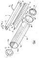
- the device comprises a compact fluorescent lamp whose tube in U comprises two tubular branches 2, 2 'arranged side by side, their axes respective being substantially parallel.
- the light source 1 is such a U-shaped lamp.
- a grid 3 juxtaposed with the lamp 1 is intended to improve the luminance of the device.
- This grid 3 is fixedly attached to the lamp 1.
- This grid 3 comprises on the one hand two bars 4, 4 ′ which are substantially parallel and on the other hand a plurality of identical flat parts 5 arranged in parallel to each other and perpendicular to each of the two bars 4, 4 ', said parts 5 being integral with each of the two bars 4, 4 '.
- each of the two bars 4, 4 ' has at least two holes 8, the position of the holes 8 being identical on the two bars 4, 4 '.
- the hooks 7 of the springs 6 engage in the holes 8 of the bars 4, 4 ', the lamp 1 being located substantially parallel to the bars 4, 4', between said bars 4, 4 'and the springs 6.
- the parts 5 of the grids 3 have the form of a half disc limited by a linear edge and a circular edge.
- the edge linear, intended to be juxtaposed with the lamp 1, follows the shape of said lamp 1.
- each half disc has two notches 9 in the form of a half disc in which the branches 2, 2 ′ of the lamp 1 are positioned.
- cylinder we mean any solid generated by the set of straight lines based on a guide curve and parallel to an axis.
- the cylinder 10 is preferably a cylinder of revolution, but the device according to the invention is not limited to this geometry. In particular, we can consider replacing the cylinder of revolution with a cylinder based ellipsoidal or by a prismatic element.
- the device also includes two rings 12, 13 placed at the ends of cylinder 10, said rings 12, 13 being fixed inside an apparatus lighting, for example by screws.
- the rings 12, 13 have, on one of their faces, an annular part 14 protruding from engaging inside the cylinder 10.
- a functional clearance between the internal wall of the cylinder 10 and the external wall of the annular part 14 allows the rotation of the cylinder 10 around said rings 12, 13, while the lamp 1 and grid 3 remain fixed.
- the cylinder 10 can be maneuvered in rotation about its axis 11, and therefore around the lamp 1, by a thumbwheel, not shown, or any other device associated with said cylinder 10.
- the cylinder 10 may include a cylindrical extension 30, of the same axis 11 and of circular section.
- the outer diameter of this cylindrical extension 30 is preferably slightly less than the diameter of cylinder 10.
- the outer wall 33 of the ring 31 is rough, so that a user can maneuver the cylinder 10 in rotation about the axis 11 by means of the ring 31 without his fingers sliding on the external wall 33.
- the cylinder 10 has on its surface at least two zones 15a, 15b having each with a different light transmission coefficient.
- these zones 15a, 15b extend substantially parallel to the axis 11 of the cylinder 10 over substantially the entire length of cylinder 10, tel. that depicted on the figure 1.
- the cylinder 10 has four zones 15a, 15b, 15c, 15d arranged as described above, each area covering substantially a quarter of the surface of the cylinder 10.
- the zones 15a, 15b, 15c, 15d are distributed so that, turning around the cylinder 10 in one direction given, the light transmission coefficients of the zones successively encountered are 0%, 100%, 35% and 100% respectively.
- the invention also provides that the light transmission coefficient varies continuously and gradually from 0% to 100% starting from a generator of cylinder 10 and turning around said cylinder 10 in one direction given.
- the cylinder 10 is made of polycarbonate or any other material transparent.
- the zones 15a, 15b having transmission coefficients of the different light are formed on cylinder 10 by printing, coloring in the mass, or any other equivalent process.
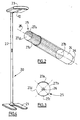
- Such a device can for example be used in a lamp post 20, as illustrated in figure 4.
- the lamp includes a base 21, a mast 22 and an upper part 23 in which is placed the device for varying the intensity transmitted light.
- At least a portion of the cylinder 10 is visible outside the portion upper 23 of the lamppost 20, said portion extending over the entire length of cylinder 10.
- the rotation of the cylinder 10 around its axis 11 has the effect of placing between the lamp 1 and the space to be lit an area with a transmission coefficient of light more or less important. In this way, the light intensity transmitted in direct lighting can vary between 0 and 100%.
- lamp 1 If another portion of cylinder 10 is visible at the level of the portion upper 23 of lamppost 20, the remainder of light emitted by lamp 1 can be transmitted in indirect lighting.
- a second cylinder 24 which has the same characteristics as the cylinder 10 of the first mode of realization, except for the transmission of light.
- the second cylinder 24 is substantially transparent.
- the second cylinder 24 is a cylinder of revolution.
- the device comprises rings engaging inside the second cylinder 24, and around which said second cylinder 24 can rotate, being for example actuated by a wheel, or any other device.
- the second cylinder 24 may include a extension 34 capable of receiving a rough ring intended to facilitate the rotary handling of said second cylinder 24.
- this flexible cylinder 25 is produced from a film, which can be a very thin polycarbonate sheet.
- This flexible cylinder 25 is kept in contact with the second cylinder 24 by its elasticity.
- the flexible cylinder 25 is slid inside the second cylinder 24, as shown in Figure 2, but it is also possible to place said 25 on the outer surface of the second cylinder 24.
- the flexible cylinder 25 has on its surface at least two zones 27a, 27b each having a different light transmittance. Of preferably, these zones 27a, 27b extend substantially parallel to the axis 26 of the flexible cylinder 25 over substantially the entire length of the cylinder flexible 25.
- the flexible cylinder 25 has four zones 27a, 27b, 27c, 27d arranged as described above, each zone 27a, 27b, 27c, 27d covering substantially a quarter of the surface of the cylinder flexible 25.
- the zones 27a, 27b, 27c, 27d are distributed so that, in rotating around the flexible cylinder 25 in a given direction, the coefficients of light transmission successively encountered areas are 0%, 100%, 35% and 100% respectively, as shown in Figure 3.
- the light transmission coefficient can vary gradually from 0% to 100% when turning around the cylinder flexible 25 in a given direction.
- Areas with different light coefficients are for example formed on the flexible cylinder 25 by printing.
- the flexible cylinder 25 being integral with the second cylinder 24, the rotation of the second cylinder 24 allows, as previously, to vary the intensity light transmitted from the lamp 1.
- the invention can thus be applied to any lighting device, and not only to the lampposts.
- the invention provides in particular the possibility of interposing between the source 1 and the space to be lit a flat screen, the surface of which presents at least two zones with distinct light transmission coefficients.
- the displacement in translation of this screen relative to the light source thus allows to pass, for example through a slit, a light which the light intensity varies depending on the position of the screen.
Landscapes
- Engineering & Computer Science (AREA)
- General Engineering & Computer Science (AREA)
- Physics & Mathematics (AREA)
- Spectroscopy & Molecular Physics (AREA)
- Non-Portable Lighting Devices Or Systems Thereof (AREA)
Applications Claiming Priority (2)
| Application Number | Priority Date | Filing Date | Title |
|---|---|---|---|
| FR9916657 | 1999-12-29 | ||
| FR9916657A FR2803368B1 (fr) | 1999-12-29 | 1999-12-29 | Dispositif permettant de faire varier l'intensite lumineuse transmise depuis une source lumineuse |
Publications (1)
| Publication Number | Publication Date |
|---|---|
| EP1113221A1 true EP1113221A1 (de) | 2001-07-04 |
Family
ID=9553969
Family Applications (1)
| Application Number | Title | Priority Date | Filing Date |
|---|---|---|---|
| EP00403214A Withdrawn EP1113221A1 (de) | 1999-12-29 | 2000-11-17 | Vorrichtung zur Veränderung der durchgelassenen Lichtstärke einer Lichtquelle |
Country Status (2)
| Country | Link |
|---|---|
| EP (1) | EP1113221A1 (de) |
| FR (1) | FR2803368B1 (de) |
Cited By (1)
| Publication number | Priority date | Publication date | Assignee | Title |
|---|---|---|---|---|
| WO2013113548A1 (en) * | 2012-01-30 | 2013-08-08 | Osram Gmbh | Led tube |
Citations (4)
| Publication number | Priority date | Publication date | Assignee | Title |
|---|---|---|---|---|
| FR2420084A1 (fr) * | 1978-03-13 | 1979-10-12 | Vedres Laurent | Appareil d'eclairage selectif a flux reglable |
| CH668822A5 (en) * | 1985-12-05 | 1989-01-31 | Alrane Inventing Ag | Sales promotion show box - contg. fluorescent lamps carrying graded light shading plastic strips, for uniform illumination |
| US4991070A (en) * | 1989-07-12 | 1991-02-05 | Herman Miller, Inc. | Sleeve for a light element |
| DE29724052U1 (de) * | 1997-09-15 | 1999-10-28 | Beckert, Ulrich, 80337 München | Leuchte zur Erzeugung eines Lichts mit regelbarem Farbton |
-
1999
- 1999-12-29 FR FR9916657A patent/FR2803368B1/fr not_active Expired - Fee Related
-
2000
- 2000-11-17 EP EP00403214A patent/EP1113221A1/de not_active Withdrawn
Patent Citations (4)
| Publication number | Priority date | Publication date | Assignee | Title |
|---|---|---|---|---|
| FR2420084A1 (fr) * | 1978-03-13 | 1979-10-12 | Vedres Laurent | Appareil d'eclairage selectif a flux reglable |
| CH668822A5 (en) * | 1985-12-05 | 1989-01-31 | Alrane Inventing Ag | Sales promotion show box - contg. fluorescent lamps carrying graded light shading plastic strips, for uniform illumination |
| US4991070A (en) * | 1989-07-12 | 1991-02-05 | Herman Miller, Inc. | Sleeve for a light element |
| DE29724052U1 (de) * | 1997-09-15 | 1999-10-28 | Beckert, Ulrich, 80337 München | Leuchte zur Erzeugung eines Lichts mit regelbarem Farbton |
Cited By (1)
| Publication number | Priority date | Publication date | Assignee | Title |
|---|---|---|---|---|
| WO2013113548A1 (en) * | 2012-01-30 | 2013-08-08 | Osram Gmbh | Led tube |
Also Published As
| Publication number | Publication date |
|---|---|
| FR2803368A1 (fr) | 2001-07-06 |
| FR2803368B1 (fr) | 2002-07-05 |
Similar Documents
| Publication | Publication Date | Title |
|---|---|---|
| FR2495279A1 (fr) | Appareil d'eclairage | |
| CA2041906A1 (fr) | Dispositif d'eclairage | |
| FR2607904A1 (fr) | Appareil d'eclairage muni d'un reflecteur a facettes | |
| EP0233465B1 (de) | Vorrichtung mit einem abnehmbaren Träger für Deckeneinbauleuchten | |
| EP3549281A1 (de) | Vorrichtung zur beleuchtung und optischen kommunikation in kombination mit der ansicht des kommunikationsfeldes | |
| EP0318390B1 (de) | Apparatur für Ausstrahlung von elektromagnetischen Wellen, insbesondere für den Infrarotbereich, mit einer planaren Quelle von Strahlen und einem Reflektor | |
| FR2569824A1 (fr) | Dispositif reflecteur pour appareils d'eclairage de salles d'operation | |
| WO2008061986A1 (fr) | Boite a gant a enceinte etanche eclairee | |
| FR2803368A1 (fr) | Dispositif permettant de faire varier l'intensite lumineuse transmise depuis une source lumineuse | |
| EP0159594A1 (de) | Belichtungsvorrichtung mit hoher Diffusionsfähigkeit | |
| EP2809546B1 (de) | Led-beleuchtungsvorrichtung mit einem diffusorsystem | |
| FR2889767A1 (fr) | Retro eclairage d'un bouton de commande avec guide lumiere. | |
| WO2004079259A1 (fr) | Dispositif d'eclairage | |
| EP1475564A1 (de) | Halte- und Verstellvorrichtung zur Ausrichtung eines Reflektors, für eine in den Grund eingebaute Leuchte | |
| EP1109200A1 (de) | Elektrische Birne mit einem Spiegel und Beleuchtungsleiste mit wenigstens einer solchen Birne | |
| EP1167071B1 (de) | Bildwiedergabevorrichtung | |
| EP0466584B1 (de) | Scheinwerfer | |
| FR2685373A1 (fr) | Amelioration pour un dispositif d'etayage. | |
| EP0813951A1 (de) | Übertragungsring für Luftreifen oder für Luftreifengürtel | |
| EP1191573A1 (de) | Kolbenlampe mit Vorrichtung zur Kurzschlussvermeidung | |
| FR2496840A1 (fr) | Feu de signalisation | |
| FR2745366A3 (fr) | Luminaire fournissant un eclairage direct et un eclairage indirect | |
| EP0375528A1 (de) | Gerät zur Manipulierung eines lichtreflektierenden Spiegels | |
| FR2899008A1 (fr) | Dispositif d'affichage a ecran a cristaux liquides. | |
| FR2615929A1 (fr) | Feu de signalisation rond a lampe a decharge |
Legal Events
| Date | Code | Title | Description |
|---|---|---|---|
| PUAI | Public reference made under article 153(3) epc to a published international application that has entered the european phase |
Free format text: ORIGINAL CODE: 0009012 |
|
| AK | Designated contracting states |
Kind code of ref document: A1 Designated state(s): AT BE CH CY DE DK ES FI FR GB GR IE IT LI LU MC NL PT SE TR |
|
| AX | Request for extension of the european patent |
Free format text: AL;LT;LV;MK;RO;SI |
|
| 17P | Request for examination filed |
Effective date: 20010514 |
|
| AKX | Designation fees paid |
Free format text: AT BE CH CY DE DK ES FI FR GB GR IE IT LI LU MC NL PT SE TR |
|
| STAA | Information on the status of an ep patent application or granted ep patent |
Free format text: STATUS: THE APPLICATION IS DEEMED TO BE WITHDRAWN |
|
| 18D | Application deemed to be withdrawn |
Effective date: 20050601 |