EP1113564A1 - Machine électrique tournante dont le stator et/ou le rotor comporte des évidements périphériques - Google Patents
Machine électrique tournante dont le stator et/ou le rotor comporte des évidements périphériques Download PDFInfo
- Publication number
- EP1113564A1 EP1113564A1 EP00403550A EP00403550A EP1113564A1 EP 1113564 A1 EP1113564 A1 EP 1113564A1 EP 00403550 A EP00403550 A EP 00403550A EP 00403550 A EP00403550 A EP 00403550A EP 1113564 A1 EP1113564 A1 EP 1113564A1
- Authority
- EP
- European Patent Office
- Prior art keywords
- rotor
- stator
- sheet
- sheets
- legs
- Prior art date
- Legal status (The legal status is an assumption and is not a legal conclusion. Google has not performed a legal analysis and makes no representation as to the accuracy of the status listed.)
- Granted
Links
- 230000002093 peripheral effect Effects 0.000 title claims abstract description 30
- XEEYBQQBJWHFJM-UHFFFAOYSA-N Iron Chemical compound [Fe] XEEYBQQBJWHFJM-UHFFFAOYSA-N 0.000 claims abstract description 10
- 229910052742 iron Inorganic materials 0.000 claims abstract description 5
- 239000002184 metal Substances 0.000 claims description 15
- 229910052751 metal Inorganic materials 0.000 claims description 15
- 239000000696 magnetic material Substances 0.000 abstract 1
- 238000004519 manufacturing process Methods 0.000 description 4
- 210000000078 claw Anatomy 0.000 description 2
- 238000004804 winding Methods 0.000 description 2
- 229910000831 Steel Inorganic materials 0.000 description 1
- 230000015572 biosynthetic process Effects 0.000 description 1
- 230000001627 detrimental effect Effects 0.000 description 1
- 238000010438 heat treatment Methods 0.000 description 1
- 238000000034 method Methods 0.000 description 1
- 239000007858 starting material Substances 0.000 description 1
- 239000010959 steel Substances 0.000 description 1
Images
Classifications
-
- H—ELECTRICITY
- H02—GENERATION; CONVERSION OR DISTRIBUTION OF ELECTRIC POWER
- H02K—DYNAMO-ELECTRIC MACHINES
- H02K1/00—Details of the magnetic circuit
- H02K1/06—Details of the magnetic circuit characterised by the shape, form or construction
Definitions
- the invention relates to a rotary electrical machine.
- the invention relates more particularly to a machine electric rotating about an axis, of the type comprising a rotor and stator, and of the type in which the rotor and / or the stator has a substantially cylindrical annular body which consists of an axial stack of cut sheets forming a bundle of sheets.
- the rotor and stator carcasses of a rotating electric machine each consist of a block of laminated sheets.
- This block of laminated sheets is a stack of sheets of steel insulated from each other to remedy the birth of Eddy currents likely to cause heating detrimental to the proper functioning of the machine.
- the machine comprises a rotor and a stator comprising a stack of sheets for formation of the magnetic circuit, the rotor being machined and then striated.
- the object of the present invention is to respond to this wish.
- a machine of the above-mentioned type is characterized in that the outer diameter, respectively internal, of each sheet plate varies by at least one sector angular to another between a maximum diameter value and a minimum diameter value, and two adjacent sheets are stacked so that a value angular sector of maximum diameter of a sheet facing a sector angular value of minimum diameter of an adjacent sheet.
- each sheet has legs, which form the poles of the rotor and / or stator, one at less legs with a smaller radial size than other legs.
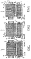
- FIG. 1 Schematically shown in Figure 1 a rotor 10 and a stator 12 of a rotary electric machine 14 such than an alternator or an electric starter motor.
- the rotor 10 and the stator 12 comprise each an annular body 16, 18 substantially cylindrical with an axis X-X and whose structure is laminated, that is to say that each annular body 16, 18 is formed by an axial stack of sheets.
- the sheets are obtained from thin plates of sheet metal, i.e. sheets of sheet metal cut to form sheet bundles.
- the rotor 10 and the stator 12 being symmetrical with respect to at their X-X axis, they are shown in half-view.
- the rotor 10 and the stator 12 also include winding windings 11 and 13.
- the rotor 10 is mounted for rotation about the axis X-X at inside the stator 12.
- the radial interval E which separates the peripheral face convex external axial 20 of the rotor 10 of the peripheral face concave internal axial 22 of stator 12 constitutes the air gap of the machine 14.
- the body 16 of the rotor 10 consists of an axial stack of sheets of different external diameters forming a bundle of sheets.
- stator 12 which then includes circumferential peripheral recesses in its concave internal axial peripheral face 22, and employ a “smooth” rotor 10 according to the state of the art.
- FIG. 2 shows a variant of the first embodiment in which the body 18 of the stator 12 similarly to the body 16 of the rotor 10 shown in Figure 1, that is to say by means of a stack axial of sheets with angular sectors of diameters different internal.
- the sheets 24 are stacked axially, 26, 30, 32 of the rotor 10 and of the stator 12 so that the recesses 28 circumferential peripherals of the rotor 10 are axially opposite the peripheral 34 recesses stator circumferentials 12.
- the sheets 24 are stacked axially, 26, 30, 32 of the rotor 10 and of the stator 12 so that the recesses 28 circumferential peripherals of the rotor 10 are axially offset from the peripheral 34 recesses stator circumferentials 12.
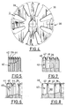
- FIG. 4 shows a sheet 36 of rotor 10 in the form of a thin plate or sheet cut in a fashion for carrying out the invention.
- legs 38, 39 here at number eight, from sheet metal 36 which form the poles of rotor 10.
- the legs 38 are of radial size greater than those of legs 39.
- this sheet 36 has its outer diameter De which varies from at least one angular sector to another, between a value of minimum diameter De min and a value of maximum diameter De max , showing a difference or offset D between these diameters.
- a pair of legs of minimum external diameter alternate with a pair of legs of maximum external diameter.
- the sheet metal plates 36 are stacked axially by angularly shifting, once in two, a sheet metal plate 36 by a quarter turn so that two legs 39 of minimum external diameter De min of a sheet 36 are opposite two legs 38 of maximum external diameter De max of an adjacent sheet 36.
- This arrangement makes it possible to show portions circumferential peripheral recesses in the face convex external axial device 20 of the rotor 10.
- This embodiment makes it possible to use only one and same tool for cutting sheets 36 which are all identical, which reduces investments by adding the assembly operation consisting of angularly shifting the sheets 36 every second time.
- three legs of external diameter minimum succeed three legs of maximum external diameter and we stack the sheets so that three legs minimum external diameter of a sheet face three legs of maximum external diameter of an adjacent sheet.
- each sheet has only one lug minimum internal diameter.
- stator 12 then comprising two tabs of minimum internal diameter of a sheet facing two legs maximum internal diameter of an adjacent sheet.
- each sheet of the rotor and / or the stator has lugs, which form the poles of the rotor and stator., at least one of the legs having a radial size lower than other legs.
- FIG. 5 The detail is shown diagrammatically in FIG. 5 of an axial stacking of sheets 40 according to another mode of production.
- peripheral edge 42 radially outer of each rotor sheet 10 has one face bevelled transverse 44.
- the bevelling of the peripheral edges 42 can be carried out by any known means.
- beveling is carried out using the cutting tool (not shown) for the sheets 40, for example in using a special form of the plate cutting tool thin or sheet metal.
- the axial stacking of the sheet metal plates 40 of the rotor 10 is here done so that the bevelled face 44 of each sheet metal plate 40 is oriented axially on the same side. This arrangement allows a recess to appear 28 circumferential device between each sheet 40 and a sheet 40 adjacent.
- the edge external device 42 of each sheet 40 of rotor 10 comprises two opposite bevelled faces 46, 48.
- the sheets do not necessarily have a shape plane. They are arranged in bundles of sheets.
Landscapes
- Engineering & Computer Science (AREA)
- Power Engineering (AREA)
- Iron Core Of Rotating Electric Machines (AREA)
- Manufacture Of Motors, Generators (AREA)
Abstract
Description
- le bord périphérique externe, respectivement interne, d'une tôle comporte au moins une face biseautée ;
- la ou les faces biseautées de la tôle est réalisée par l'outil de découpe des tôles ;
- les paquets de tôle du rotor et du stator comportent des évidements circonférentiels et le rotor est monté à l'intérieur du stator de manière que ses évidements circonférentiels soient axialement en vis-à-vis des évidements circonférentiels du stator ;
- les paquets de tôle du rotor et du stator comportent des évidements circonférentiels et le rotor est monté à l'intérieur du stator de manière que ses évidements circonférentiels soient décalés axialement par rapport aux évidements circonférentiels du stator.
- la figure 1 est une demi-vue schématique en coupe axiale qui représente le rotor et le stator d'une machine électrique tournante réalisée selon un premier mode de réalisation de l'invention ;
- les figures 2 et 3 sont des vues similaires à la précédente qui représentent des variantes du premier mode de réalisation ;
- la figure 4 est une vue schématique de face d'une plaque de tôle de rotor d'une machine électrique réalisée selon un second mode de réalisation de l'invention ;
- la figure 5 est vue schématique d'un détail d'empilage des tôles de rotor d'une machine électrique réalisée selon un troisième mode de réalisation de l'invention ;
- les figures 6 à 8 sont des vues similaires à celle de la figure 5 qui représentent des variantes du troisième mode de réalisation.
Claims (6)
- Machine électrique tournante (14) autour d'un axe (X-X), du type comportant un rotor (10) et un stator (12), et du type dans lequel le rotor (10) et/ou le stator (12) comporte un corps annulaire (16, 18) sensiblement cylindrique qui est constitué par un empilage axial de tôles découpées formant un paquet de tôles comportant des évidements périphériques circonférentiels (28, 34) en vue de diminuer les pertes fer dans la machine (14), caractérisée en ce que le diamètre externe (De), respectivement interne (Di), de chaque tôle (36) varie d'au moins un secteur angulaire à un autre entre une valeur de diamètre maximal (Demax) et une valeur de diamètre minimal (Demin), et en ce que deux tôles (36) adjacentes sont empilées de manière qu'un secteur angulaire de valeur de diamètre maximal (Demax) d'une tôle (36) soit en vis-à-vis d'un secteur angulaire de valeur de diamètre minimal (Demin) d'une plaque de tôle (36) adjacente.
- Machine (14) selon la revendication précédente, caractérisée en ce que les paquets de tôle du rotor (10) et du stator (12) comportent des évidements circonférentiels (28, 34) et en ce que le rotor (10) est monté à l'intérieur du stator (12) de manière que ses évidements circonférentiels (28) soient en vis-à-vis des évidements circonférentiels (34) du stator (12).
- Machine (14) selon la revendication 1, cearactérisé en ce que les paquets de tôles du rotor (10) du stator (12) comportent des évidements circonférentiels et en ce que le rotor (10) est monté à l'intérieur du stator (12) de manière à ce que ses évidements circonférentiels soient axialement en vis-à-vis des évidements circonférentiels du stator (12).
- Machine (14) selon l'une quelconque des revendications précédentes, caractérisée en ce que le bord périphérique externe (42), respectivement interne, d'une tôle (40) comporte au moins une face (44, 48) biseautée, et en ce que la ou les faces (44, 48) biseautées de la tôle (40) est réalisée par l'outil de découpe des tôles (40).
- Machine selon l'une quelconque des revendications 1 à 4, caractérisé en ce que chaque tôle comporte des pattes (38,39 qui forment des pôles du rotor (10) et/ou du stator (12) et en ce qu'au moins l'une des pattes a une taille radiale à celle des autres pattes pour formation desdits évidements.
- Machine selon l'une quelconque des revendications 1 à 5, caractérisé en ce que chaque tôle comporte des pattes (38,39) qui forment des pôles du rotor (10) et en ce que le diamètre externe (De) varie tous les quarts de tours de manière à ce que deux pattes (39) de diamètre externe minimal (Demin) succèdent à deux pattes (38) de diamètre externe maximal (Demax).
Applications Claiming Priority (2)
| Application Number | Priority Date | Filing Date | Title |
|---|---|---|---|
| FR9916730 | 1999-12-30 | ||
| FR9916730A FR2803449B1 (fr) | 1999-12-30 | 1999-12-30 | Machine electrique tournante dont le stator et/ou le rotor comporte des evidements peripheriques |
Publications (2)
| Publication Number | Publication Date |
|---|---|
| EP1113564A1 true EP1113564A1 (fr) | 2001-07-04 |
| EP1113564B1 EP1113564B1 (fr) | 2006-01-18 |
Family
ID=9554042
Family Applications (1)
| Application Number | Title | Priority Date | Filing Date |
|---|---|---|---|
| EP20000403550 Expired - Lifetime EP1113564B1 (fr) | 1999-12-30 | 2000-12-15 | Machine électrique tournante dont le stator et/ou le rotor comporte des évidements périphériques |
Country Status (4)
| Country | Link |
|---|---|
| EP (1) | EP1113564B1 (fr) |
| DE (1) | DE60025583T2 (fr) |
| ES (1) | ES2254121T3 (fr) |
| FR (1) | FR2803449B1 (fr) |
Cited By (1)
| Publication number | Priority date | Publication date | Assignee | Title |
|---|---|---|---|---|
| EP1596486A3 (fr) * | 2004-05-14 | 2006-09-13 | National-Oilwell, L.P. | Lamelles métalliques pour circuits magnétiques |
Families Citing this family (2)
| Publication number | Priority date | Publication date | Assignee | Title |
|---|---|---|---|---|
| DE102006034578A1 (de) * | 2006-07-26 | 2008-01-31 | Siemens Ag | Elektrische Maschine mit variierendem Luftspalt |
| DE102020202337A1 (de) * | 2020-02-24 | 2021-08-26 | BSH Hausgeräte GmbH | Wäschepflegegerät mit elektrischem Antrieb |
Citations (5)
| Publication number | Priority date | Publication date | Assignee | Title |
|---|---|---|---|---|
| CH196052A (de) * | 1936-06-29 | 1938-02-28 | Jakob Bohli | Mit einem Stator und einem Rotor versehene magnetelektrische Maschine. |
| US3504153A (en) * | 1965-10-11 | 1970-03-31 | Lloyd Dynamowerke Gmbh | Method of spark machining stator or rotor having lamination simulating characteristics |
| JPS5389902A (en) * | 1977-01-18 | 1978-08-08 | Mitsubishi Electric Corp | Layers-core |
| JPH02131339A (ja) * | 1988-11-07 | 1990-05-21 | Nippon Denso Co Ltd | 交流発電機 |
| JPH11103549A (ja) * | 1997-09-28 | 1999-04-13 | Sanyo Electric Co Ltd | 電動送風機 |
-
1999
- 1999-12-30 FR FR9916730A patent/FR2803449B1/fr not_active Expired - Fee Related
-
2000
- 2000-12-15 DE DE2000625583 patent/DE60025583T2/de not_active Expired - Fee Related
- 2000-12-15 EP EP20000403550 patent/EP1113564B1/fr not_active Expired - Lifetime
- 2000-12-15 ES ES00403550T patent/ES2254121T3/es not_active Expired - Lifetime
Patent Citations (5)
| Publication number | Priority date | Publication date | Assignee | Title |
|---|---|---|---|---|
| CH196052A (de) * | 1936-06-29 | 1938-02-28 | Jakob Bohli | Mit einem Stator und einem Rotor versehene magnetelektrische Maschine. |
| US3504153A (en) * | 1965-10-11 | 1970-03-31 | Lloyd Dynamowerke Gmbh | Method of spark machining stator or rotor having lamination simulating characteristics |
| JPS5389902A (en) * | 1977-01-18 | 1978-08-08 | Mitsubishi Electric Corp | Layers-core |
| JPH02131339A (ja) * | 1988-11-07 | 1990-05-21 | Nippon Denso Co Ltd | 交流発電機 |
| JPH11103549A (ja) * | 1997-09-28 | 1999-04-13 | Sanyo Electric Co Ltd | 電動送風機 |
Non-Patent Citations (3)
| Title |
|---|
| PATENT ABSTRACTS OF JAPAN vol. 002, no. 124 (E - 064) 18 October 1978 (1978-10-18) * |
| PATENT ABSTRACTS OF JAPAN vol. 014, no. 368 (E - 0962) 9 August 1990 (1990-08-09) * |
| PATENT ABSTRACTS OF JAPAN vol. 1999, no. 09 30 July 1999 (1999-07-30) * |
Cited By (1)
| Publication number | Priority date | Publication date | Assignee | Title |
|---|---|---|---|---|
| EP1596486A3 (fr) * | 2004-05-14 | 2006-09-13 | National-Oilwell, L.P. | Lamelles métalliques pour circuits magnétiques |
Also Published As
| Publication number | Publication date |
|---|---|
| ES2254121T3 (es) | 2006-06-16 |
| FR2803449B1 (fr) | 2006-04-07 |
| DE60025583D1 (de) | 2006-04-06 |
| DE60025583T2 (de) | 2006-07-20 |
| FR2803449A1 (fr) | 2001-07-06 |
| EP1113564B1 (fr) | 2006-01-18 |
Similar Documents
| Publication | Publication Date | Title |
|---|---|---|
| FR2932618A1 (fr) | Rotor a aimants permanents et machine tournante comportant un tel rotor | |
| FR2924282A1 (fr) | Procede de fabrication de machine electrique tournante et machine electrique tournante | |
| FR2924283A1 (fr) | Procede de fabrication de machine electrique tournante et machine electrique tournante | |
| FR3084535A1 (fr) | Rotor de machine electrique avec poles asymetriques | |
| EP2817868A1 (fr) | Rotor de machine tournante a concentration de flux | |
| EP2209192A1 (fr) | Machine électrique tournante, en particulier pour un démarreur de véhicule automobile | |
| FR3082373A1 (fr) | Stator de machine electrique tournante | |
| FR2742936A1 (fr) | Machine electrique synchrome a aimants permanents adaptee a fonctionner a puissance constante sur une large plage de vitesse | |
| WO2024132599A1 (fr) | Stator de machine électrique à flux axial | |
| WO2024132600A1 (fr) | Stator de machine électrique à flux axial | |
| EP1113564B1 (fr) | Machine électrique tournante dont le stator et/ou le rotor comporte des évidements périphériques | |
| EP2283561A2 (fr) | Rotor de machine electrique tournante avec structures interpolaires a masse reduite | |
| EP4264807A1 (fr) | Corps de stator pour machine electrique a flux axial et procede de fabrication d'un tel corps de stator | |
| FR2850215A1 (fr) | Armature d'une machine electrique rotative et demarreur comportant l'armature | |
| EP2005554B1 (fr) | Rotor de machine electrique tournante comportant des gorges pour aimants | |
| WO2023094747A1 (fr) | Rotor de machine électrique tournante | |
| WO2003012954A2 (fr) | Machine electrique avec stator a poles griffes | |
| FR2983007A1 (fr) | Rotor de machine electrique tournante a aimants permanents. | |
| FR3143229A1 (fr) | Rotor de machine électrique comprenant au moins un évidement avec un ergot ou une gorge de profil arrondi | |
| EP4113796A1 (fr) | Machine electrique tournante | |
| FR3037734B1 (fr) | Rotor a toles empilees. | |
| WO2020043966A1 (fr) | Procede d'equilibrage d'un rotor de moteur electrique avec usinage du paquet de toles | |
| FR2809240A1 (fr) | Machine electrique homopolaire et procede de fabrication d'une telle machine | |
| WO2018154218A1 (fr) | Rotor de machine électrique tournante a configuration améliorée | |
| FR2955988A1 (fr) | Rotor a aimants permanents. |
Legal Events
| Date | Code | Title | Description |
|---|---|---|---|
| PUAI | Public reference made under article 153(3) epc to a published international application that has entered the european phase |
Free format text: ORIGINAL CODE: 0009012 |
|
| AK | Designated contracting states |
Kind code of ref document: A1 Designated state(s): DE ES GB IT |
|
| AX | Request for extension of the european patent |
Free format text: AL;LT;LV;MK;RO;SI |
|
| 17P | Request for examination filed |
Effective date: 20011127 |
|
| AKX | Designation fees paid |
Free format text: DE ES GB IT |
|
| GRAP | Despatch of communication of intention to grant a patent |
Free format text: ORIGINAL CODE: EPIDOSNIGR1 |
|
| GRAS | Grant fee paid |
Free format text: ORIGINAL CODE: EPIDOSNIGR3 |
|
| GRAA | (expected) grant |
Free format text: ORIGINAL CODE: 0009210 |
|
| AK | Designated contracting states |
Kind code of ref document: B1 Designated state(s): DE ES GB IT |
|
| REG | Reference to a national code |
Ref country code: GB Ref legal event code: FG4D Free format text: NOT ENGLISH |
|
| REF | Corresponds to: |
Ref document number: 60025583 Country of ref document: DE Date of ref document: 20060406 Kind code of ref document: P |
|
| GBT | Gb: translation of ep patent filed (gb section 77(6)(a)/1977) |
Effective date: 20060503 |
|
| REG | Reference to a national code |
Ref country code: ES Ref legal event code: FG2A Ref document number: 2254121 Country of ref document: ES Kind code of ref document: T3 |
|
| PLBE | No opposition filed within time limit |
Free format text: ORIGINAL CODE: 0009261 |
|
| STAA | Information on the status of an ep patent application or granted ep patent |
Free format text: STATUS: NO OPPOSITION FILED WITHIN TIME LIMIT |
|
| 26N | No opposition filed |
Effective date: 20061019 |
|
| PGFP | Annual fee paid to national office [announced via postgrant information from national office to epo] |
Ref country code: ES Payment date: 20081222 Year of fee payment: 9 |
|
| PGFP | Annual fee paid to national office [announced via postgrant information from national office to epo] |
Ref country code: IT Payment date: 20081219 Year of fee payment: 9 |
|
| PGFP | Annual fee paid to national office [announced via postgrant information from national office to epo] |
Ref country code: DE Payment date: 20081210 Year of fee payment: 9 |
|
| PGFP | Annual fee paid to national office [announced via postgrant information from national office to epo] |
Ref country code: GB Payment date: 20081204 Year of fee payment: 9 |
|
| GBPC | Gb: european patent ceased through non-payment of renewal fee |
Effective date: 20091215 |
|
| PG25 | Lapsed in a contracting state [announced via postgrant information from national office to epo] |
Ref country code: DE Free format text: LAPSE BECAUSE OF NON-PAYMENT OF DUE FEES Effective date: 20100701 |
|
| PG25 | Lapsed in a contracting state [announced via postgrant information from national office to epo] |
Ref country code: GB Free format text: LAPSE BECAUSE OF NON-PAYMENT OF DUE FEES Effective date: 20091215 |
|
| REG | Reference to a national code |
Ref country code: ES Ref legal event code: FD2A Effective date: 20110302 |
|
| PG25 | Lapsed in a contracting state [announced via postgrant information from national office to epo] |
Ref country code: IT Free format text: LAPSE BECAUSE OF NON-PAYMENT OF DUE FEES Effective date: 20091215 |
|
| PG25 | Lapsed in a contracting state [announced via postgrant information from national office to epo] |
Ref country code: ES Free format text: LAPSE BECAUSE OF NON-PAYMENT OF DUE FEES Effective date: 20110301 |
|
| PG25 | Lapsed in a contracting state [announced via postgrant information from national office to epo] |
Ref country code: ES Free format text: LAPSE BECAUSE OF NON-PAYMENT OF DUE FEES Effective date: 20091216 |