EP1114503B1 - Moteur a collecteur - Google Patents
Moteur a collecteur Download PDFInfo
- Publication number
- EP1114503B1 EP1114503B1 EP00931025A EP00931025A EP1114503B1 EP 1114503 B1 EP1114503 B1 EP 1114503B1 EP 00931025 A EP00931025 A EP 00931025A EP 00931025 A EP00931025 A EP 00931025A EP 1114503 B1 EP1114503 B1 EP 1114503B1
- Authority
- EP
- European Patent Office
- Prior art keywords
- motor
- base body
- pulse
- commutator
- Prior art date
- Legal status (The legal status is an assumption and is not a legal conclusion. Google has not performed a legal analysis and makes no representation as to the accuracy of the status listed.)
- Expired - Lifetime
Links
- 238000012544 monitoring process Methods 0.000 claims 1
- 238000007790 scraping Methods 0.000 claims 1
- 238000001514 detection method Methods 0.000 description 5
- 238000004519 manufacturing process Methods 0.000 description 2
- 238000004804 winding Methods 0.000 description 2
- 230000005540 biological transmission Effects 0.000 description 1
- 238000011161 development Methods 0.000 description 1
- 230000018109 developmental process Effects 0.000 description 1
- 238000003780 insertion Methods 0.000 description 1
- 230000037431 insertion Effects 0.000 description 1
- 238000000034 method Methods 0.000 description 1
- 230000005405 multipole Effects 0.000 description 1
- 238000005507 spraying Methods 0.000 description 1
Images

Classifications
-
- B—PERFORMING OPERATIONS; TRANSPORTING
- B60—VEHICLES IN GENERAL
- B60J—WINDOWS, WINDSCREENS, NON-FIXED ROOFS, DOORS, OR SIMILAR DEVICES FOR VEHICLES; REMOVABLE EXTERNAL PROTECTIVE COVERINGS SPECIALLY ADAPTED FOR VEHICLES
- B60J7/00—Non-fixed roofs; Roofs with movable panels, e.g. rotary sunroofs
- B60J7/02—Non-fixed roofs; Roofs with movable panels, e.g. rotary sunroofs of sliding type, e.g. comprising guide shoes
- B60J7/04—Non-fixed roofs; Roofs with movable panels, e.g. rotary sunroofs of sliding type, e.g. comprising guide shoes with rigid plate-like element or elements, e.g. open roofs with harmonica-type folding rigid panels
- B60J7/057—Driving or actuating arrangements e.g. manually operated levers or knobs
- B60J7/0573—Driving or actuating arrangements e.g. manually operated levers or knobs power driven arrangements, e.g. electrical
-
- H—ELECTRICITY
- H02—GENERATION; CONVERSION OR DISTRIBUTION OF ELECTRIC POWER
- H02K—DYNAMO-ELECTRIC MACHINES
- H02K23/00—DC commutator motors or generators having mechanical commutator; Universal AC/DC commutator motors
- H02K23/66—Structural association with auxiliary electric devices influencing the characteristic of, or controlling, the machine, e.g. with impedances or switches
-
- E—FIXED CONSTRUCTIONS
- E05—LOCKS; KEYS; WINDOW OR DOOR FITTINGS; SAFES
- E05F—DEVICES FOR MOVING WINGS INTO OPEN OR CLOSED POSITION; CHECKS FOR WINGS; WING FITTINGS NOT OTHERWISE PROVIDED FOR, CONCERNED WITH THE FUNCTIONING OF THE WING
- E05F15/00—Power-operated mechanisms for wings
- E05F15/60—Power-operated mechanisms for wings using electrical actuators
- E05F15/603—Power-operated mechanisms for wings using electrical actuators using rotary electromotors
- E05F15/665—Power-operated mechanisms for wings using electrical actuators using rotary electromotors for vertically-sliding wings
- E05F15/689—Power-operated mechanisms for wings using electrical actuators using rotary electromotors for vertically-sliding wings specially adapted for vehicle windows
- E05F15/697—Motor units therefor, e.g. geared motors
-
- E—FIXED CONSTRUCTIONS
- E05—LOCKS; KEYS; WINDOW OR DOOR FITTINGS; SAFES
- E05Y—INDEXING SCHEME ASSOCIATED WITH SUBCLASSES E05D AND E05F, RELATING TO CONSTRUCTION ELEMENTS, ELECTRIC CONTROL, POWER SUPPLY, POWER SIGNAL OR TRANSMISSION, USER INTERFACES, MOUNTING OR COUPLING, DETAILS, ACCESSORIES, AUXILIARY OPERATIONS NOT OTHERWISE PROVIDED FOR, APPLICATION THEREOF
- E05Y2900/00—Application of doors, windows, wings or fittings thereof
- E05Y2900/50—Application of doors, windows, wings or fittings thereof for vehicles
- E05Y2900/53—Type of wing
- E05Y2900/542—Roof panels
-
- E—FIXED CONSTRUCTIONS
- E05—LOCKS; KEYS; WINDOW OR DOOR FITTINGS; SAFES
- E05Y—INDEXING SCHEME ASSOCIATED WITH SUBCLASSES E05D AND E05F, RELATING TO CONSTRUCTION ELEMENTS, ELECTRIC CONTROL, POWER SUPPLY, POWER SIGNAL OR TRANSMISSION, USER INTERFACES, MOUNTING OR COUPLING, DETAILS, ACCESSORIES, AUXILIARY OPERATIONS NOT OTHERWISE PROVIDED FOR, APPLICATION THEREOF
- E05Y2900/00—Application of doors, windows, wings or fittings thereof
- E05Y2900/50—Application of doors, windows, wings or fittings thereof for vehicles
- E05Y2900/53—Type of wing
- E05Y2900/55—Windows
-
- H—ELECTRICITY
- H02—GENERATION; CONVERSION OR DISTRIBUTION OF ELECTRIC POWER
- H02K—DYNAMO-ELECTRIC MACHINES
- H02K7/00—Arrangements for handling mechanical energy structurally associated with dynamo-electric machines, e.g. structural association with mechanical driving motors or auxiliary dynamo-electric machines
- H02K7/10—Structural association with clutches, brakes, gears, pulleys or mechanical starters
- H02K7/116—Structural association with clutches, brakes, gears, pulleys or mechanical starters with gears
- H02K7/1163—Structural association with clutches, brakes, gears, pulleys or mechanical starters with gears where at least two gears have non-parallel axes without having orbital motion
- H02K7/1166—Structural association with clutches, brakes, gears, pulleys or mechanical starters with gears where at least two gears have non-parallel axes without having orbital motion comprising worm and worm-wheel
Definitions
- the invention relates to a commutator motor, in particular Actuator for vehicle units, such as window regulators, Sunroof and the like, which in the preamble of claim 1 defined genus.
- a known commutator motor of this type (DE 196 53 209 A1) are for the rotation detection of the motor, and for both speed and direction detection, the pulse generator as a multi-pole magnetized magnet wheel and two Pulse receivers attached to the brush holder as Hall IC trained who without a separate individual bracket on the Brush holders are housed in close proximity to the magnet wheel.
- the motor shaft on the one hand and the Hall IC on the Brush holders are guaranteed to Motor housing as well as on a commutator side, the Motor shaft receiving end shield in the area of their mutual assembly system alignment means, e.g.
- axial guide pins which axial guide openings adapted to the motor housing or fasteners, e.g. in the form of that End shield molded, axial flare / caulking lugs, by the corresponding attachment to the motor housing pluggable and then in the sense of a mutual fixation deformable, in particular, caulkable, are provided.
- the commutator motor according to the invention with the features of Claim 1 has the advantage that due to the tolerance placed bag, which during the spraying process for the Brush holder body is molded in at the same time, none additional components for adjusting and fastening the Pulse receiver are required.
- the end position of the Impulse receiver is specified with high precision, and the The pulse receiver is positively fixed in this end position.
- the rotation detection device is for automatic Suitable assembly and their manufacturing and assembly costs are minimal.
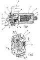
- Geared motor for a window regulator of a motor vehicle has a transmission receiving in a known manner Gear housing 10 and a gear housing 10 flanged motor housing 11 one as trained permanent magnet commutator motor Electric motor.
- gear housing 10 In the motor housing 11 is in a known manner a stator 12 is attached, one on a rotor shaft 13 rotatably seated rotor 14 leaving an air gap encloses.
- the rotor shaft 13 is in the motor housing 11 by means of a pivot bearing 15 and rotatable in the gear housing 10 stored.
- a commutator sits on the rotor shaft 13 in a rotationally fixed manner 16, on the commutator blades of the rotor or Armature winding 17 is connected.
- the power supply to Armature winding 17 takes place via current or commutator brushes 18, which are held on a brush holder 19 and with radially directed spring force on the circumference of the Commutator 16 lying commutator blades are pressed.
- the brush holder 19 has one in the gear housing 10 fixed and coaxially surrounding the rotor shaft 13 Base body 20 and a radially to the base body 20th plugged in contact plug 21, via which the power supply to the commutator brushes 18 held on the base body 20 he follows.
- both the Speed as well as the direction of rotation of the commutator motor are detected, for which purpose a rotation detection device 22nd is provided, which in a known manner on the Rotor shaft 13 non-rotatable pulse generator 23 and two spatially fixed, in the direction of rotation by 90 ° to each other offset pulse receiver 24 includes.
- the establishment of the Pulse receiver 24 is on the base body 20 of the Brush holder 19 made.
- Embodiment of the rotation detection device 22 is the Pulse generator 23 as a ring magnet, which of the base body 20 of the Brush holder 18 is enclosed without contact, and everyone Pulse receiver 24 designed as a so-called. Hall sensor. The How the ring magnet works in conjunction with the two Hall sensors is known, so no further details are given here needs to be received.
- the base body 20 of the brush holder 19 is in Fig. 2 in Shown top view.
- To accommodate the pulse receiver 24 are formed in the base body 20 two pockets 25, which around 90 ° in the circumferential direction are offset from each other and the have the same radial distance from the base body axis.
- In each of these pockets 25 there is a pulse receiver 24 positively inserted and has a in its end position highly precise alignment to the pulse generator 23.
- the bags 25 are in the top view of FIG Base body 20 of the brush holder 19 is dashed indicated and in the sectional views according to FIGS. 3-5 recognizable in more detail.
- the longitudinal axis of the pockets 25 extends tangentially to on the rotor shaft 13 non-rotatable pulse generator 23 and the pulse receiver 24 is in each case up to the pocket base 251 in the pocket 25 inserted, the pocket 25 the pulse receiver 24th form-fitting.
- the pocket base 251 forms one Stop when inserting the pulse receiver 24 and defines the end position of the pulse receiver 24 in Longitudinal axis of the pocket 25 introduced control opening 26 (Fig. 4 and 5), the End position of the pulse receiver 24 on the pocket base 251 optically and check mechanically. 4 and 5 show in which the bag 25 in two different cuts without inserted pulse receiver 24 is shown, the Pocket 25 has a funnel-shaped pocket opening 252, whereby the insertion of the pulse receiver 24 is essential is facilitated.
- Pulse receiver 24 can be seen in section.
- the one as a Hall sensor trained pulse receiver 24 has a Hall element receiving housing 27, from which three lugs 28th protrude. When in its end position within the pocket 25 itself located pulse receiver 24 enter the lugs 28th out of the pocket 25 axially, and are electrical Crosspieces arranged in the contact plug 21 Pins electrically connected.
- the housing 27 the pulse receiver 24 has a bottom wall 271, one to it in parallel distance extending ceiling wall 272, the Area is smaller than that of the bottom wall 271 and two Sidewalls 273.
- the side walls 273 each have one first side wall section 273a, and a Sidewall portion 273b.
- the two side wall sections 273a extend parallel to each other, while the Sidewall portions 273b toward the top wall 272 run trapezoidal inwards.
- the Pulse receiver 24 in the pocket 25 supports the housing 27 of the pulse receiver 24 with its bottom wall 271 on two spaced from one another, designed as so-called shaving ribs Axial webs 29 which protrude from one pocket wall 253 and with its trapezoidal shape
- Sidewall portions 273b formed in the pocket 25 Bevels 254 from that of the axial webs 29 Pocket wall 253 are opposite.
- the height of the axial webs 29 increases slightly in the direction of the pocket depth, so that in the end position of the housing 27 determined by the pocket base 251 the housing 27 against the bevels 254 and the axial webs 29 pressed wid. This is the radial distance between the Pulse generator 23 and the pulse receiver 24 exactly defined.
Landscapes
- Engineering & Computer Science (AREA)
- Power Engineering (AREA)
- Mechanical Engineering (AREA)
- Motor Or Generator Frames (AREA)
- Dc Machiner (AREA)
- Motor Or Generator Current Collectors (AREA)
- Transmission And Conversion Of Sensor Element Output (AREA)
- Connection Of Motors, Electrical Generators, Mechanical Devices, And The Like (AREA)
Claims (7)
- Moteur à collecteur, notamment moteur d'actionneur pour l'équipement de véhicule, tel que la vitre ou le toit coulissant ou analogues, comportant un collecteur (16) solidaire en rotation de l'arbre (11) du moteur, un support de balais (19) ayant un corps de base (20) fixé au boítier (11) du moteur et des balais de commutateur (18) appliqués par une liaison par la force à la périphérie du collecteur, et un dispositif (22) pour détecter la rotation (vitesse de rotation et/ou sens de rotation) du moteur comprenant un générateur d'impulsion (23) solidaire en rotation de l'arbre (13) du moteur et au moins un récepteur d'impulsion (24) fixé à un support de balais (19) notamment un capteur Hall,
caractérisé en ce que
le corps de base (20) du support de balais (19) entoure sans contact le générateur d'impulsion (23), et
au moins un capteur d'impulsion (24) est placé par une liaison de forme dans une cavité (25) réalisée dans le corps de base (20). - Moteur selon la revendication 1,
caractérisé en ce que
l'axe longitudinal de la cavité (25) est aligné sensiblement dans une direction tangentielle à l'arbre (13) du moteur et le récepteur d'impulsion (24) est glissé suivant une liaison par la forme jusqu'en appui contre le fond (251) de la cavité (25). - Moteur selon la revendication 2,
caractérisé en ce qu'
une ouverture de contrôle (26) est réalisée dans la cavité (25) perpendiculairement à son axe longitudinal, cette ouverture débouchant à l'extérieur du corps de base (20) et dans la cavité (25). - Moteur selon l'une des revendications 1 à 3,
caractérisé en ce que
le capteur d'impulsion (24) comporte un boítier (27) avec un fond (271), un dessus (272) et deux parois latérales (273),
les parois latérales (273) ont des segments de parois latérales (273b) dirigées vers l'intérieur suivant un tracé trapézoïdal, du côté du dessus (272), et le boítier (27) s'appuie d'une part par son fond (271) contre les nervures axiales (29) en saillie de la paroi (253) de la cavité, de préférence les nervures de raclage, et d'autre part par ses segments de paroi latérale (273b) contre les surfaces inclinées (254) de la cavité (25). - Moteur selon la revendication 4,
caractérisé en ce que
la hauteur des nervures axiales (29) augmente légèrement en direction du fond (251) de la cavité. - Moteur selon l'une des revendications 1 à 5,
caractérisé en ce que
le corps de base (20) du support de balai (19) comporte deux cavités (25) de même type pour recevoir chacune un capteur d'impulsion (24), ces cavités étant décalées l'une par rapport à l'autre de 90° dans le sens de rotation de l'arbre (13) du moteur. - Moteur selon l'une des revendications 1 à 6,
caractérisé en ce que
le générateur d'impulsion (23) est un aimant annulaire.
Applications Claiming Priority (3)
| Application Number | Priority Date | Filing Date | Title |
|---|---|---|---|
| DE19924631 | 1999-05-29 | ||
| DE19924631A DE19924631A1 (de) | 1999-05-29 | 1999-05-29 | Kommutatormotor |
| PCT/DE2000/001190 WO2000074216A2 (fr) | 1999-05-29 | 2000-04-15 | Moteur a collecteur |
Publications (2)
| Publication Number | Publication Date |
|---|---|
| EP1114503A2 EP1114503A2 (fr) | 2001-07-11 |
| EP1114503B1 true EP1114503B1 (fr) | 2003-07-09 |
Family
ID=7909573
Family Applications (1)
| Application Number | Title | Priority Date | Filing Date |
|---|---|---|---|
| EP00931025A Expired - Lifetime EP1114503B1 (fr) | 1999-05-29 | 2000-04-15 | Moteur a collecteur |
Country Status (7)
| Country | Link |
|---|---|
| US (1) | US6664698B1 (fr) |
| EP (1) | EP1114503B1 (fr) |
| JP (1) | JP4532043B2 (fr) |
| BR (1) | BR0006161A (fr) |
| DE (2) | DE19924631A1 (fr) |
| ES (1) | ES2203476T3 (fr) |
| WO (1) | WO2000074216A2 (fr) |
Families Citing this family (7)
| Publication number | Priority date | Publication date | Assignee | Title |
|---|---|---|---|---|
| JP4569046B2 (ja) * | 2001-05-29 | 2010-10-27 | 株式会社デンソー | 電動機 |
| EP1429449B1 (fr) * | 2001-09-17 | 2017-03-01 | Mitsubishi Denki Kabushiki Kaisha | Stabilisateur de couple pour servomoteur sans balai |
| US6791218B1 (en) * | 2003-03-20 | 2004-09-14 | Siemens Vdo Automotive Inc. | Stall protection for brush motors with rotation sensing brush device |
| US6998754B2 (en) * | 2004-03-05 | 2006-02-14 | Energy Conversion Systems Holdings, Llc | Brush assemblies |
| DE102007024249A1 (de) * | 2007-05-18 | 2008-12-11 | CoActive Technologies, Inc., Greenwich | Vorrichtung zum Erfassen eines Stellwinkels eines um eine Achse drehbaren Elementes |
| DE102009045138A1 (de) * | 2009-09-30 | 2011-03-31 | Zf Friedrichshafen Ag | Befestigungsanordnung für einen Trägerring, Herstellungsverfahren und Werkzeug |
| JP2020165321A (ja) * | 2019-03-28 | 2020-10-08 | 日本電産トーソク株式会社 | 電動オイルポンプ |
Family Cites Families (21)
| Publication number | Priority date | Publication date | Assignee | Title |
|---|---|---|---|---|
| JPS5895957A (ja) * | 1981-12-01 | 1983-06-07 | Shibaura Eng Works Co Ltd | 無刷子電動機の組立方法 |
| JPH025665Y2 (fr) * | 1985-10-22 | 1990-02-09 | ||
| JPS62290343A (ja) * | 1986-06-09 | 1987-12-17 | Matsushita Electric Ind Co Ltd | ブラシレス直流モ−タ |
| JPS6339448A (ja) * | 1986-07-31 | 1988-02-19 | Fujitsu General Ltd | 電動機におけるロ−タ位置検出素子の取付装置 |
| US5053664A (en) * | 1989-01-18 | 1991-10-01 | Aisan Kogyo Kabushiki Kaisha | Motor-driven fuel pump |
| FR2684817A1 (fr) * | 1991-12-06 | 1993-06-11 | Valeo Systemes Dessuyage | Machine electrodynamique a circuit electrique de service integre. |
| DE4233156A1 (de) * | 1992-10-02 | 1994-04-07 | Bosch Gmbh Robert | Elektromotorischer Antrieb |
| EP0618659B2 (fr) * | 1993-03-31 | 2001-07-04 | Siemens Aktiengesellschaft | Unité d'entraínement à moteur-réducteur, en particulier pour lève-glace de véhicule à moteur |
| JPH0684782U (ja) * | 1993-05-10 | 1994-12-02 | 株式会社富士通ゼネラル | 電動機の位置検出用ホール素子取付構造 |
| JPH0734319U (ja) * | 1993-12-06 | 1995-06-23 | 株式会社三ツ葉電機製作所 | 回転検出装置 |
| JPH08275462A (ja) * | 1995-03-27 | 1996-10-18 | Kusatsu Denki Kk | 速度検出器付電動機 |
| DE19651660B4 (de) * | 1996-12-12 | 2012-08-30 | Dr. Fritz Faulhaber Gmbh & Co. Kg | Mikroelektromotor |
| DE19704472A1 (de) * | 1997-02-06 | 1998-08-13 | Bosch Gmbh Robert | Elektromotor |
| DE19710015A1 (de) * | 1997-03-12 | 1998-09-17 | Bosch Gmbh Robert | Motor mit Drehzahlabgriff über einen Hall-Sensor |
| JPH1118391A (ja) * | 1997-06-25 | 1999-01-22 | Jidosha Denki Kogyo Co Ltd | 小型モータ |
| DE19739682A1 (de) * | 1997-09-10 | 1999-03-11 | Bosch Gmbh Robert | Sensoreinrichtung |
| DE19805185A1 (de) * | 1998-02-10 | 1999-08-12 | Bosch Gmbh Robert | Antriebsvorrichtung, insbesondere zum Verstellen eines Schiebedachs eines Fahrzeugs |
| JP4025436B2 (ja) * | 1998-02-17 | 2007-12-19 | アスモ株式会社 | モータ |
| DE19916958A1 (de) * | 1999-04-15 | 2000-10-19 | Bosch Gmbh Robert | Elektromotorischer Antrieb, insbesondere Fensterheberantrieb für ein Kraftfahrzeug |
| DE10007696A1 (de) * | 2000-02-19 | 2001-08-23 | Bosch Gmbh Robert | Elektromotoren, insbesondere zum Heben und Senken von Scheiben bei Kraftfahrzeugen |
| US6707188B2 (en) * | 2000-05-08 | 2004-03-16 | Asmo Co., Ltd. | Motor having rotational sensor |
-
1999
- 1999-05-29 DE DE19924631A patent/DE19924631A1/de not_active Ceased
-
2000
- 2000-04-15 DE DE50002822T patent/DE50002822D1/de not_active Expired - Lifetime
- 2000-04-15 US US09/744,671 patent/US6664698B1/en not_active Expired - Fee Related
- 2000-04-15 BR BR0006161-1A patent/BR0006161A/pt not_active IP Right Cessation
- 2000-04-15 EP EP00931025A patent/EP1114503B1/fr not_active Expired - Lifetime
- 2000-04-15 JP JP2001500415A patent/JP4532043B2/ja not_active Expired - Fee Related
- 2000-04-15 WO PCT/DE2000/001190 patent/WO2000074216A2/fr not_active Ceased
- 2000-04-15 ES ES00931025T patent/ES2203476T3/es not_active Expired - Lifetime
Also Published As
| Publication number | Publication date |
|---|---|
| EP1114503A2 (fr) | 2001-07-11 |
| WO2000074216A2 (fr) | 2000-12-07 |
| DE50002822D1 (de) | 2003-08-14 |
| JP2003501997A (ja) | 2003-01-14 |
| WO2000074216A3 (fr) | 2001-04-19 |
| BR0006161A (pt) | 2001-04-17 |
| DE19924631A1 (de) | 2000-11-30 |
| ES2203476T3 (es) | 2004-04-16 |
| US6664698B1 (en) | 2003-12-16 |
| JP4532043B2 (ja) | 2010-08-25 |
Similar Documents
| Publication | Publication Date | Title |
|---|---|---|
| EP0996213B1 (fr) | Connecteur pour moteur, notamment pour moteur à collecteur à vitesse réglable | |
| DE3787479T2 (de) | Bürstenhalter für dynamoelektrische Maschine. | |
| EP0920723B1 (fr) | Unite d'entrainement electrique | |
| EP1057239B1 (fr) | Moteur a engrenage electrique pour groupes de vehicule | |
| EP0359853B1 (fr) | Entraînement à moteur électrique en particulier servo d'entraînement pour un véhicule | |
| WO1998040751A1 (fr) | Moteur a regime detecte par un capteur de hall | |
| EP0981457B1 (fr) | Dispositif d'entrainement pour un element, pouvant se deplacer entre des positions finales, d'un vehicule et son procede de production | |
| EP1425842B1 (fr) | Unite d'entrainement comportant un moteur electrique, destinee a des dispositifs de reglage de vehicules | |
| EP1046217B1 (fr) | Moteur electrique | |
| DE4326391C2 (de) | Dreherkennungsvorrichtung für einen Kommutatormotor | |
| EP1528656B1 (fr) | Porte-balais pour un mécanisme de commande à moteur électrique et mécanisme de commande à moteur électrique | |
| DE9006935U1 (de) | Elektromotorischer Antrieb | |
| WO2017071910A1 (fr) | Système de balais d'un moteur électrique | |
| WO2007121828A2 (fr) | Bloc pour un moteur à collecteur, moteur à collecteur comprenant ce bloc et procédé de montage d'un tel moteur à collecteur | |
| EP1114503B1 (fr) | Moteur a collecteur | |
| DE2410630C3 (de) | Impulsdrehzahlgeber | |
| EP1969700B1 (fr) | Rotor et machine électrique contenant celui-ci | |
| DE102009001714A1 (de) | Elektrischer Antriebsmotor, insbesondere für ein Aggregat in einem Kraftfahrzeug | |
| EP0786856B1 (fr) | Dispositif de commutation pour moteur à courant continu sans balais | |
| EP1800957B1 (fr) | Dispositif de transmission de signal ou de courant entre des terminaux | |
| DE102018121225A1 (de) | Scheibenwischermotor und Verfahren zur Montage des Scheibenwischermotors | |
| WO2024165685A1 (fr) | Ensemble stator pour un moteur électrique et dispositif d'entraînement | |
| WO2022128555A1 (fr) | Systèmes de balais pour moteur électrique | |
| DE102007057454A1 (de) | Handwerkzeugmaschine mit in einem Gehäuse verlaufenden Kabeln | |
| WO2011091889A1 (fr) | Auxiliaire de montage pour une machine électrique à commutation par balais |
Legal Events
| Date | Code | Title | Description |
|---|---|---|---|
| PUAI | Public reference made under article 153(3) epc to a published international application that has entered the european phase |
Free format text: ORIGINAL CODE: 0009012 |
|
| AK | Designated contracting states |
Kind code of ref document: A2 Designated state(s): AT BE CH CY DE DK ES FI FR GB GR IE IT LI LU MC NL PT SE |
|
| AX | Request for extension of the european patent |
Free format text: AL;LT;LV;MK;RO;SI |
|
| 17P | Request for examination filed |
Effective date: 20011019 |
|
| GRAH | Despatch of communication of intention to grant a patent |
Free format text: ORIGINAL CODE: EPIDOS IGRA |
|
| GRAH | Despatch of communication of intention to grant a patent |
Free format text: ORIGINAL CODE: EPIDOS IGRA |
|
| GRAA | (expected) grant |
Free format text: ORIGINAL CODE: 0009210 |
|
| AK | Designated contracting states |
Designated state(s): DE ES FR GB IT |
|
| REG | Reference to a national code |
Ref country code: GB Ref legal event code: FG4D Free format text: NOT ENGLISH |
|
| REF | Corresponds to: |
Ref document number: 50002822 Country of ref document: DE Date of ref document: 20030814 Kind code of ref document: P |
|
| REG | Reference to a national code |
Ref country code: IE Ref legal event code: FG4D Free format text: GERMAN |
|
| GBT | Gb: translation of ep patent filed (gb section 77(6)(a)/1977) |
Effective date: 20031029 |
|
| LTIE | Lt: invalidation of european patent or patent extension |
Effective date: 20030709 |
|
| REG | Reference to a national code |
Ref country code: IE Ref legal event code: FD4D |
|
| ET | Fr: translation filed | ||
| REG | Reference to a national code |
Ref country code: ES Ref legal event code: FG2A Ref document number: 2203476 Country of ref document: ES Kind code of ref document: T3 |
|
| PLBE | No opposition filed within time limit |
Free format text: ORIGINAL CODE: 0009261 |
|
| STAA | Information on the status of an ep patent application or granted ep patent |
Free format text: STATUS: NO OPPOSITION FILED WITHIN TIME LIMIT |
|
| 26N | No opposition filed |
Effective date: 20040414 |
|
| REG | Reference to a national code |
Ref country code: DE Ref legal event code: R084 Ref document number: 50002822 Country of ref document: DE Effective date: 20140502 |
|
| PGFP | Annual fee paid to national office [announced via postgrant information from national office to epo] |
Ref country code: GB Payment date: 20140423 Year of fee payment: 15 |
|
| PGFP | Annual fee paid to national office [announced via postgrant information from national office to epo] |
Ref country code: ES Payment date: 20140417 Year of fee payment: 15 Ref country code: DE Payment date: 20140626 Year of fee payment: 15 Ref country code: FR Payment date: 20140416 Year of fee payment: 15 Ref country code: IT Payment date: 20140429 Year of fee payment: 15 |
|
| REG | Reference to a national code |
Ref country code: DE Ref legal event code: R119 Ref document number: 50002822 Country of ref document: DE |
|
| GBPC | Gb: european patent ceased through non-payment of renewal fee |
Effective date: 20150415 |
|
| PG25 | Lapsed in a contracting state [announced via postgrant information from national office to epo] |
Ref country code: DE Free format text: LAPSE BECAUSE OF NON-PAYMENT OF DUE FEES Effective date: 20151103 Ref country code: IT Free format text: LAPSE BECAUSE OF NON-PAYMENT OF DUE FEES Effective date: 20150415 Ref country code: GB Free format text: LAPSE BECAUSE OF NON-PAYMENT OF DUE FEES Effective date: 20150415 |
|
| REG | Reference to a national code |
Ref country code: FR Ref legal event code: ST Effective date: 20151231 |
|
| PG25 | Lapsed in a contracting state [announced via postgrant information from national office to epo] |
Ref country code: FR Free format text: LAPSE BECAUSE OF NON-PAYMENT OF DUE FEES Effective date: 20150430 |
|
| REG | Reference to a national code |
Ref country code: ES Ref legal event code: FD2A Effective date: 20160527 |
|
| PG25 | Lapsed in a contracting state [announced via postgrant information from national office to epo] |
Ref country code: ES Free format text: LAPSE BECAUSE OF NON-PAYMENT OF DUE FEES Effective date: 20150416 |