EP1114666A2 - Procédé pour l'ajustage et l'équilibrage d'un dispositif d'adsorption à pression alternée sous vide - Google Patents
Procédé pour l'ajustage et l'équilibrage d'un dispositif d'adsorption à pression alternée sous vide Download PDFInfo
- Publication number
- EP1114666A2 EP1114666A2 EP01100398A EP01100398A EP1114666A2 EP 1114666 A2 EP1114666 A2 EP 1114666A2 EP 01100398 A EP01100398 A EP 01100398A EP 01100398 A EP01100398 A EP 01100398A EP 1114666 A2 EP1114666 A2 EP 1114666A2
- Authority
- EP
- European Patent Office
- Prior art keywords
- bed
- pressure
- cycle
- adsorption
- steps
- Prior art date
- Legal status (The legal status is an assumption and is not a legal conclusion. Google has not performed a legal analysis and makes no representation as to the accuracy of the status listed.)
- Granted
Links
- 0 CC1*CCC1 Chemical compound CC1*CCC1 0.000 description 1
Images
Classifications
-
- B—PERFORMING OPERATIONS; TRANSPORTING
- B01—PHYSICAL OR CHEMICAL PROCESSES OR APPARATUS IN GENERAL
- B01D—SEPARATION
- B01D53/00—Separation of gases or vapours; Recovering vapours of volatile solvents from gases; Chemical or biological purification of waste gases, e.g. engine exhaust gases, smoke, fumes, flue gases, aerosols
- B01D53/02—Separation of gases or vapours; Recovering vapours of volatile solvents from gases; Chemical or biological purification of waste gases, e.g. engine exhaust gases, smoke, fumes, flue gases, aerosols by adsorption, e.g. preparative gas chromatography
- B01D53/04—Separation of gases or vapours; Recovering vapours of volatile solvents from gases; Chemical or biological purification of waste gases, e.g. engine exhaust gases, smoke, fumes, flue gases, aerosols by adsorption, e.g. preparative gas chromatography with stationary adsorbents
- B01D53/047—Pressure swing adsorption
- B01D53/0476—Vacuum pressure swing adsorption
-
- B—PERFORMING OPERATIONS; TRANSPORTING
- B01—PHYSICAL OR CHEMICAL PROCESSES OR APPARATUS IN GENERAL
- B01D—SEPARATION
- B01D2256/00—Main component in the product gas stream after treatment
- B01D2256/12—Oxygen
-
- B—PERFORMING OPERATIONS; TRANSPORTING
- B01—PHYSICAL OR CHEMICAL PROCESSES OR APPARATUS IN GENERAL
- B01D—SEPARATION
- B01D2259/00—Type of treatment
- B01D2259/40—Further details for adsorption processes and devices
- B01D2259/40007—Controlling pressure or temperature swing adsorption
-
- B—PERFORMING OPERATIONS; TRANSPORTING
- B01—PHYSICAL OR CHEMICAL PROCESSES OR APPARATUS IN GENERAL
- B01D—SEPARATION
- B01D2259/00—Type of treatment
- B01D2259/40—Further details for adsorption processes and devices
- B01D2259/40011—Methods relating to the process cycle in pressure or temperature swing adsorption
- B01D2259/40058—Number of sequence steps, including sub-steps, per cycle
- B01D2259/40075—More than ten
-
- B—PERFORMING OPERATIONS; TRANSPORTING
- B01—PHYSICAL OR CHEMICAL PROCESSES OR APPARATUS IN GENERAL
- B01D—SEPARATION
- B01D2259/00—Type of treatment
- B01D2259/40—Further details for adsorption processes and devices
- B01D2259/402—Further details for adsorption processes and devices using two beds
-
- B—PERFORMING OPERATIONS; TRANSPORTING
- B01—PHYSICAL OR CHEMICAL PROCESSES OR APPARATUS IN GENERAL
- B01D—SEPARATION
- B01D53/00—Separation of gases or vapours; Recovering vapours of volatile solvents from gases; Chemical or biological purification of waste gases, e.g. engine exhaust gases, smoke, fumes, flue gases, aerosols
- B01D53/02—Separation of gases or vapours; Recovering vapours of volatile solvents from gases; Chemical or biological purification of waste gases, e.g. engine exhaust gases, smoke, fumes, flue gases, aerosols by adsorption, e.g. preparative gas chromatography
- B01D53/04—Separation of gases or vapours; Recovering vapours of volatile solvents from gases; Chemical or biological purification of waste gases, e.g. engine exhaust gases, smoke, fumes, flue gases, aerosols by adsorption, e.g. preparative gas chromatography with stationary adsorbents
- B01D53/0407—Constructional details of adsorbing systems
- B01D53/0431—Beds with radial gas flow
-
- B—PERFORMING OPERATIONS; TRANSPORTING
- B01—PHYSICAL OR CHEMICAL PROCESSES OR APPARATUS IN GENERAL
- B01D—SEPARATION
- B01D53/00—Separation of gases or vapours; Recovering vapours of volatile solvents from gases; Chemical or biological purification of waste gases, e.g. engine exhaust gases, smoke, fumes, flue gases, aerosols
- B01D53/02—Separation of gases or vapours; Recovering vapours of volatile solvents from gases; Chemical or biological purification of waste gases, e.g. engine exhaust gases, smoke, fumes, flue gases, aerosols by adsorption, e.g. preparative gas chromatography
- B01D53/04—Separation of gases or vapours; Recovering vapours of volatile solvents from gases; Chemical or biological purification of waste gases, e.g. engine exhaust gases, smoke, fumes, flue gases, aerosols by adsorption, e.g. preparative gas chromatography with stationary adsorbents
- B01D53/047—Pressure swing adsorption
- B01D53/053—Pressure swing adsorption with storage or buffer vessel
Definitions
- This invention relates to control of a pressure swing gas separation process and, more particularly, to a method for adjusting adsorption / desorption step times and vessel reflux step times and flows, based on observed pressures and purities, to maintain vessel pressures slightly below or at predetermined values in order to optimize and achieve maximum production.
- US Patent 4,747,853 to Haslett et al. describes a method of over pressurization control, for cases of valve failure, that utilizes a pressure sensing device, a flow restricting-orifice and a normally open valve. If the pressure sensing unit detects unacceptable pressures, a signal is sent to the normally open valve, causing it to close. The downstream system is thus protected from the higher pressure in a manner similar to commercially available relief valves or bursting disks.
- US Patent #5,529607 to Ziming Tan indicates that maximum O 2 concentration measured in purge gas effluent from individual beds being operated out of phase in a cyclic PSA process, can be monitored. Then the absolute difference of the concentrations can be determined and adjustments made to the purge process step time of each bed in a manner which reduces the absolute value of the concentration difference.
- US Patent 5,486,226 to Ross et al. uses an oxygen analyzer to measure impurity in a carbon PSA designed to make N 2 . If the O 2 impurity rises above acceptable limits, flow of product quality gas is initiated from a surge tank into the adsorption vessels in a manner to restore product purity. This provides a means of rapid restart after an outage or other upset.
- US Patent 5,258,056 to Shirley et al. describes a method for controlling output production from a plant by measuring a change in product demand and then adjusting the feed airflow to compensate for the change in product demand. Feed airflow is adjusted in such a manner as to maintain a constant product purity. The system controls feed air for both turndown capacity control and purity control.
- US Patent 4,725,293 to Gunderson describes a system for control of impurity levels in a product stream by monitoring purity levels of the product stream and then by adjusting feed air flow in a manner to maintain desire product purity.
- US Patent 4,693,730 to Miller et al. proposes a method for controlling the purity of a gas component in the product stream of a PSA.
- the concentration of impurity is monitored in a co-current depressurization, or equalization gas to determine if there is an upset condition present. If a problem is detected, then the process is adjusted.
- the main actions that can be undertaken to correct the purity problem are:
- the Miller et al. system monitors purity at a time in the cycle when it is changing most quickly and when upsets are most easily detected. It is thus possible to detect events before they have a chance to fully propagate and show in the product purity.
- the invention monitors system pressures, sends the monitored data to a PLC which, based on control logic, adjusts the process step times in a manner to keep the process operating safely at desired optimum pressures.
- the invention controls bottom pressures independently from top pressures, thereby providing a means to optimize both a feed blower and vacuum blower somewhat independently of each other. Since the vacuum blower is a single stage machine, maintaining an optimized cycle pressure ratio is more difficult. This is due to the fact that a larger volume of air is being processed at an elevated suction pressure (when compared to a previously utilized two stage vacuum blower).
- the prior art has attempted to control the adsorption and desorption pressures to fixed, discrete levels.
- a key feature of this invention is that the individual step times and internal reflux flows within a cycle are simultaneously adjusted. These adjustments are made in a manner that operates the cycle at a pressure ratio near the desired pressure ratio, with both top adsorption and bottom desorption pressures at constantly changing levels that are optimized for the given process and equipment operating conditions.
- Balanced vessel operation maximizes output from the entire system, further reducing overall production costs.
- the prior art has utilized purity, pressure, or temperature measurements as a means of detecting an unbalance and then made adjustments to the process in a manner to restore balance.
- This invention equalizes flows into and out of the vessels by monitoring of the individual vessel effluents (waste stream) during each entire evacuation half cycle and logging the minimum oxygen concentration found during this period of time. Then, the equalization flows (vessel effluent that is transferred from the bed currently in the adsorption phase of the cycle to the bed that is currently desorbing) are adjusted accordingly so as to achieve similar O 2 concentration in the vessel waste streams.
- a key feature of this invention is that it systematically adjusts individual cycle step times (feed time, purge time, equalization time) to keep the overall system at its optimum pressure levels. Changing step times for any purpose, without specifically choosing the times, to maintain system pressure and overall reflux requirements will result in non-optimum performance.
- the invention has no need to precisely time the recording of O 2 concentration. It simply monitors for the minimum purity for each cycle and then compares them.
- Maintaining an optimized cycle pressure ratio near the design point, along with a balancing of the adsorbent vessel effluent, provides a significant economic advantage.
- By monitoring cycle pressures and subsequently altering the cycle step times to sustain an optimum value plant performance is maximized and unnecessary shutdowns are avoided.
- maintaining a system optimized pressure ratio assures that the plant production is optimized and the power consumption is minimized.
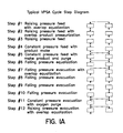
- Fig. 1A is a VPSA Cycle Step Diagram.
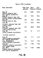
- Fig. 1B is a chart listing VPSA Process Conditions and Inner Channel Pressures.
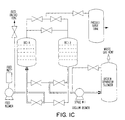
- Fig. 1C is a VPSA Equipment Diagram for carrying out the invention.
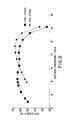
- Fig. 2 displays a graph of Vacuum Blower Efficiency vs. Vacuum Blower Suction Pressure for both a single and a two-stage vacuum blower assembly.
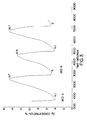
- Fig. 3 illustrates a waste (effluent) O 2 trace collected in the field.
- the invention controls a VPSA system in order to both minimize power consumption and to maintain continuous and profitable operation of the system.
- Such control is achieved by maintaining the cycle pressure ratio (Pmax/Pmin) near to a design level while maximizing the plant production.
- Control is achieved by manipulation of the cycle step times and Adjustment of equalization and purge flows. These actions help in maintaining a cycle pressure ratio near to the design while maximizing production by balancing the composition of the streams entering and leaving each adsorbent vessel.
- the overall cycle time is manipulated by changing the individual step times (purge step, equalization step and overall feed time) to produce the desired control of the cycle pressure ratio.
- the production from each of the adsorbent vessels is balanced by monitoring the composition of the vessel effluent streams. By balancing the adsorbent effluent, the efficiency and production of the plant is increased.
- the vessel effluent balancing is achieved by adjusting the equalization and purge gas flows.
- the low pressure ratio PPPOE (Product Pressurization with Purge and Overlap Equalization) cycle for a two bed VPSA system consists of 12 steps and utilizes a vacuum blower in a continuous manner. Typically, this cycle produces oxygen gas at 90-94% purity from air and operates with a short cycle time and a low bed size factor.
- the descriptions of the cycle steps below are for Bed "A”. Beds A and B undergo the exact same steps, but 180 degrees out of phase.
- Figs. 1A (VPSA Cycle Step Diagram), 1B (VPSA Process Conditions and Inner Channel Pressures) and 1C (VPSA Equipment Diagram) aid in an understanding of the process steps.
- Step 1 Rising Pressure Feed with Overlap Equalization: The feed blower is loaded during this step. Bed A (for example) is simultaneously pressurized from the bottom with feed air and from the top with equalization gas delivered from the depressurizing vessel (i.e., Bed B).
- Step 2 Rising Pressure Feed with Overlap Product Pressurization: High purity product is now added to the top of Bed A from the oxygen surge tank while feed air is supplied by the feed blower. This step is used to sharpen the adsorption front while simultaneously increasing the pressure in the bed.
- Step 3 Rising Pressure Feed: Feed continues to enter the Bed A via the feed blower. Bed A is building in pressure moving towards a set pressure before the process is permitted to make product. The pressure at the end of the step is as close as possible to the maximum adsorption pressure for the given product tank volume and pressure control system.
- Step 4 Constant Pressure Feed with Product Make: The pressure in Bed A is held relatively constant during this step by matching feed air into the vessel with product withdrawal from the top of the vessel. The product gas is delivered to the oxygen surge tank.
- Step 5 Constant Pressure Feed with Make Product and Purge: Feed air flow into the bottom of the Bed A vessel continues while the oxygen product is sent to the product surge tank and to the depressurized vessel (Bed B) as oxygen purge gas. Flows are matched to keep the vessel pressure nearly constant. The purity of the oxygen product during this step remains relatively constant and the step is terminated before the purity front breaks through the top of Bed A.
- Step 6 Falling Pressure Equalization: During this step the flow of feed gas to the Bed A vessel is discontinued by closing the feed valve. The feed air blower is unloaded by opening a vent located on the discharge side of the system. The lower purity gas remaining in the top of the pressurized Bed A is transferred to the depressurized vessel (Bed B), thus nearly equalizing the pressure in the two vessels. This is done as a process enhancement as it allows for the recovery of pressure energy and relatively high O 2 concentration gas that is contained in the top of the vessel.
- Step 7 Falling Pressure Evacuation with Overlap Equalization: The removal of waste nitrogen by the vacuum blower is initiated during this step while the Bed A vessel is simultaneously depressurized from the top by the equalization falling flow to the raising pressure adsorption vessel (Bed B).
- Steps 8, 9 and 10 Falling Pressure Evacuation: These three steps are a continuation of the evacuation period. Waste nitrogen is removed from the bottom of the Bed A vessel while there is no flow exiting or entering the top of the vessel.
- Step 11 Constant Pressure Evacuation with Oxygen Purge: The vacuum blower continues to remove nitrogen from the bottom of the Bed A vessel while oxygen purge gas is added to the top of the vessel. The pressure remains relatively constant during this step due to the fact that the oxygen purge flow is controlled equal to the evacuation flow.
- Step 12 Rising Pressure Equalization: The vacuum blower continues to evacuate nitrogen while equalization oxygen from the pressurized bed (Bed B) is fed into the top of the depressurized vessel (Bed A). The pressure in Bed A rises during this step because the equalization flow into the vessel is greater than the evacuation flow out of the vessel. The feed blower which was feeding Bed B is unloaded during this step.
- the pressure ratio for the cycle is calculated by dividing the maximum feed blower discharge pressure (occurring at the end of step 5 for Bed A; step 11 for Bed B) by the minimum vacuum blower suction pressure (occurring at the end of step 11 for Bed A; step 5 for Bed B).
- the standard pressure ratio VPSA cycle utilizes a two-stage vacuum blower and develops a large differential pressure across the vacuum blower assembly (vacuum blower suction to discharge, differential pressure ⁇ 10.5 psid).
- the low pressure ratio VPSA cycle consists of only a single stage vacuum blower and a considerably smaller differential pressure ( ⁇ 8 psid) is achieved across the vacuum blower. The resulting pressure ratio is considerably smaller than with a two stage vacuum blower assembly ( ⁇ 3 vs. ⁇ 5).
- the single stage vacuum blowers used on VPSA plants can achieve a maximum differential pressure of ⁇ 8.5 psid.
- two vacuum blowers must be used. But, by incorporating the low pressure ratio cycle, costs are lessened since only one vacuum blower is needed. Also, the process pressure ratio (which is intrinsically tied into the vacuum suction differential pressure) needs to be accurately controlled in order to enable the use of a single vacuum blower.
- the invention employs a feed blower and a single stage vacuum blower.
- the vacuum blower operates at a differential pressure near its design maximum and at pressure levels where efficiency is noticeably decreased with increasing vacuum levels.
- Fig. 2 displays a graph of Vacuum Blower Efficiency vs. Vacuum Blower Suction Pressure for both a single and a two-stage vacuum blower assembly. As the suction pressure is reduced from a suction pressure of 8 psia (vacuum blower differential pressure of ⁇ 6.5 psid) down to 6 psia ( ⁇ 8.5 psid), the pressure ratio is increasing while the efficiency of the machine is decreasing.
- PSA process pressures will remain constant with advancing time.
- the actual values that they reach each cycle will depend on the system gas storage capacity, the equipment utilized in the system, and individual step times.
- the feed air machine adds gas to the system, increasing its pressure to some high value, and the vacuum blower removes gas from the system to some low value.
- the process pressures will repeat with some average pressure. This average pressure is defined as the top and bottom pressure summed and divided by two. If more gas flows out of than into the system; top, bottom, and average pressures will fall or vise versa.
- lengthening of the cycle will increase top and reduce bottom pressures. Shortening the cycle will reduce top and increase bottom pressures. This is because more total flow is entering or exiting a fixed system but in a proportional manner.
- the average will change somewhat for each case, but its movement will be much smaller relative to the top and bottom pressure movement.
- control of at least one of the top or bottom pressures can be maintained by monitoring the pressures and changing the cycle time to maintain the pressures within tolerance or below max/min values.
- Cycle step times for steps 6 and 12, as described below, are of particular importance when effecting pressure levels as the feed blower is unloaded during those steps while the vacuum pump continues to operate. Additionally, there is internal equalization flow from vessel to vessel. Thus both flows into and out of the system, as well as flows internal to the system, can be modulated during the step so as to provide maximum effect on system pressures.
- the typical vacuum and feed blowers are selected to provide a nominal 6-7.5 psia bottom pressure and the 21-23 psia top pressure with the desired intermediate equalization, purge, overlap equalization and product pressurization steps. Pilot and field testing have demonstrated that several reflux combinations consisting of various amounts of equalization, overlap equalization and purge can be utilized to obtain a particular desired operating performance. Then by varying the amount of equalization to higher and lower level, with a subsequent lower or higher purge and overlap equalization rate, respectively, a range in top and bottom pressures can be achieved without altering the displacement of the blowers.
- the bottom pressure can be raised or lowered while maintaining a nearly constant top pressure.
- the top pressure can also be raised or lowered while maintaining a nearly constant bottom pressure by utilizing this concept simultaneously with longer or shorter adsorption steps.
- a key measure of bed balance can be determined by monitoring the O 2 concentration of the effluent for each vessel during its regeneration step. This can be accomplished with an analyzer at the outlet of each bed or, preferably, with a single analyzer in the common piping just downstream of the waste switching valves. By locating the sensor directly in the flow channel leaving the vessel, it is possible to eliminate a sample pump that would be required to draw flow from the evacuate channel.
- the equalization flows are adjusted in a manner which restores the balance. The flow is varied by sending a computer calculated setpoint to the automatic valve controlling equalization flows. A higher set point to the valve will allow more gas to flow.
- Each bed has a separate control valve for equalization thus different flows are possible for each bed.
- Fig. 3 illustrates a waste O 2 trace collected in the field. Note that bed “A” is running with a minimum waste purity of 4.1% O 2 and bed “B” is running with a minimum waste purity of 5.0 % O 2 . For this case, the proper adjustment is to increase equalization flow rate exiting Bed B and entering Bed A. The flowrate adjustments from bed to bed are done cautiously, changing the automatic control valve settings by only a few percent at a time. If these flow rates are drastically changed, the plant will become unstable and the beds will never reach a balanced state.
- tuning is much more critical than a two stage vacuum pump system.
- the performance of the adsorbent used in the VPSA oxygen system consistently improves as the overall pressure ratio increases (caused by decreasing vacuum suction pressure). Since the performance of the adsorbent used in the VPSA process is extremely sensitive to the overall pressure ratio of the process, maximizing the plant performance for a single stage vacuum pump system is important. Unbalance in a low pressure ratio process is considerably more detrimental to system capacity than in a two stage system.
- Table 1 displays process data collected from the field and a pilot plant.
- the data demonstrates the various reflux steps and their effect on VPSA operating parameters: FIELD DATA LAB DATA Data Set Descriptor Dataset 1 Dataset 2 Dataset 3 Dataset 4 Purge Step Time - sec 3.0 3.5 4.0 4.5 5.0 Equalization Step Time - sec 2.5 2.0 1.75 1.5 1.5 Bed Top Pressure - PSIA 22.2 22.2 22.2 22.1 23.7 Bed Bottom Pressure - PSIA 5.8 6.3 6.4 6.6 7.1 Plant Recovery - Percent 58.6 56.5 55.8 54.6 53.9 Product Flow Rate - STPD 167.7 166.7 167.2 166.0 - Plant Unit Power - kw/STPD 8.65 8.65 8.70 8.65 - Pressure Ratio 3.85 3.55 3.45 3.35 3.35
- FIG. 2 A plot displaying the efficiency of the Vacuum Blower Assembly (Single and Two Stage) vs. the Vacuum Suction Pressure are shown in Fig. 2.
- the graph of Fig. 2 displays how the efficiency of the Vacuum Blower Assembly changes with an increase in differential pressure (due to a decrease in suction pressure) across the assembly.
- the graph shows that for the 2-stage Vacuum Assembly, the efficiency remains relatively constant for a large segment of the graph and does not begin to decrease significantly until the suction pressure reaches ⁇ 5 psia.
- the single stage machine although it has a higher efficiency at the elevated suction pressures, begins to lose efficiency at ⁇ 10 psia.
- the single stage blower efficiency becomes worse than the two stage machine at ⁇ 8 psia and as the suction pressure drops the efficiency continues to rapidly decrease.
- the two stage machine is much more forgiving as it loses suction pressure.
- the plot shows that accurate control of the vacuum blower suction pressure along with the overall pressure ratio is important when optimizing the performance of the low pressure ratio PPPOE cycle.
- a given system is tuned for the following conditions: 6.5 PSIA bottom pressure, 21.5 PSIA top pressure, 4 second purge step, 2 second equalization step, 2 second overlap equalization step, 30 second cycle time, and operation at 80 F ambient.
- the temperature is lowered to 30 Deg F.
- a fixed displacement feed air blower will deliver approximately 10% more feed air on a mass basis and unless the cycle time is altered, the increase in mass flow will act to change the plant top pressure consistent with the new temperature conditions.
- the top pressure can be maintained as is assumed in this example.
- the ambient temperature change will not significantly affect the vacuum pump and, as a result, the bottom pressure will move away from the desired value of 6.5 psia to a higher pressure.
- the purge step can be increased to ⁇ 5 seconds with a shorter ⁇ 1.5 second equalization step and ⁇ 2 second overlap step and a slightly shorter adsorption step.
- the top pressure setpoint is established just below the feed unload pressure (set from the manufacturer recommended maximum blower differential pressure). This is done to try to operate the system as closely as possible to the desired top pressure without having the feed blower vent open, thus unloading the feed air machine. Unloading the feed blower would cause the feed air to vent and result in a process inefficiency and control disturbance to the system.
- the bottom pressure setpoint is established just above the vacuum alarm pressure (set on the VPSA system using the manufacturer recommended maximum blower differential pressure). This is done to prevent the vacuum pump from operating with too high a differential pressure which eventually can trip a shut down and cause the plant to shut down. It can also prevent the plant from running the vacuum blower at off design points from an efficiency standpoint.
- the process cycle time is automatically adjusted to operate the system such that the higher of the two bed top pressures (one each for Bed A and Bed B) is at the top pressure setpoint or the lower of the two bottom pressures is at the bottom pressure setpoint.
- the overall magnitude of pressure swing in the beds is increased or decreased by lengthening or shortening the period of time during which one bed is being fed (adsorption time) and the other is being evacuated.
- An increase in the pressure swing will occur when overall cycle time is extended because more gas is added to a "fixed” volume, thus raising the top pressure, and more gas is evacuated from the same "fixed” volume thus decreasing the bottom pressure.
- the pressure profile is shifted to higher or lower pressures by changing the amount of time the feed blower is unloaded while the vacuum blower is loaded. This is accomplished by increasing or decreasing the equalization step time. This not only changes the relative amounts of feed and evacuation; it also changes the amount of equalization gas that passes from one bed to the other. This is offset by changing the purge step timer in the opposite direction. In other words, a reduction of equalization time (and flow) is accompanied by an increase in purge time (and flow). The end result is that an increase in equalization time and a decrease in purge time will lower the top and bottom cycle pressures. A decrease in equalization time and increase in purge time will raise the top and bottom pressures.
- tuning to maintain pressure ratio adjusts the cycle to get one of the two beds to reach the top or bottom pressure setpoint, while the other bed pressures stay between these setpoints.
- Tuning to balance the vessel effluent then adjusts the cycle to locate the top and bottom pressures between the setpoints. Acting in a loop, both tuning concepts will act to maintain the overall pressure ratio and stretch the cycle such that the feed and evacuation setpoints are each reached by one bed, with neither bed passing the setpoints.
- Top and bottom pressures are checked for each bed (at the start of equalization steps 6 and 12). These values are compared against the setpoints and the offsets are calculated.
- feedtime gain x offset feedtime adjustment
- the reflux offset is calculated by subtracting the largest (in magnitude) of the two bottom offsets from the largest (in magnitude) of the two top offsets for the purge and equalization steps (reflux steps).
- These adjustments can also be positive or negative and are limited to + or -1/2 second. Maximum and minimum limits are provided for purge and equalization times.
Landscapes
- Chemical & Material Sciences (AREA)
- Engineering & Computer Science (AREA)
- Analytical Chemistry (AREA)
- General Chemical & Material Sciences (AREA)
- Oil, Petroleum & Natural Gas (AREA)
- Chemical Kinetics & Catalysis (AREA)
- Separation Of Gases By Adsorption (AREA)
- Oxygen, Ozone, And Oxides In General (AREA)
Applications Claiming Priority (2)
| Application Number | Priority Date | Filing Date | Title |
|---|---|---|---|
| US479643 | 2000-01-07 | ||
| US09/479,643 US6277174B1 (en) | 2000-01-07 | 2000-01-07 | Low pressure ratio VPSA plant tuning and balancing system |
Publications (3)
| Publication Number | Publication Date |
|---|---|
| EP1114666A2 true EP1114666A2 (fr) | 2001-07-11 |
| EP1114666A3 EP1114666A3 (fr) | 2002-07-10 |
| EP1114666B1 EP1114666B1 (fr) | 2006-10-11 |
Family
ID=23904830
Family Applications (1)
| Application Number | Title | Priority Date | Filing Date |
|---|---|---|---|
| EP01100398A Expired - Lifetime EP1114666B1 (fr) | 2000-01-07 | 2001-01-05 | Procédé pour l'ajustage et l'équilibrage d'un dispositif d'adsorption à pression alternée sous vide |
Country Status (10)
| Country | Link |
|---|---|
| US (1) | US6277174B1 (fr) |
| EP (1) | EP1114666B1 (fr) |
| JP (1) | JP4025021B2 (fr) |
| KR (1) | KR100551500B1 (fr) |
| CN (1) | CN1196512C (fr) |
| BR (1) | BR0100017B1 (fr) |
| CA (1) | CA2330360A1 (fr) |
| DE (1) | DE60123683T2 (fr) |
| ES (1) | ES2269232T3 (fr) |
| MX (1) | MXPA00013005A (fr) |
Cited By (9)
| Publication number | Priority date | Publication date | Assignee | Title |
|---|---|---|---|---|
| WO2006100398A1 (fr) * | 2005-03-25 | 2006-09-28 | L'air Liquide, Societe Anonyme Pour L'etude Et L'exploitation Des Procedes Georges Claude | Procede de reglage d'une installation de traitement par adsorption d'un gaz |
| KR100774852B1 (ko) * | 1999-12-03 | 2007-11-08 | 스미또모 가가꾸 가부시키가이샤 | 화학 증폭형 포지티브 내식막 조성물 |
| WO2007130377A3 (fr) * | 2006-05-05 | 2008-03-06 | Separation Design Group Llc | Procédé, dispositif et système de sorption |
| WO2015049462A1 (fr) * | 2013-10-04 | 2015-04-09 | L'air Liquide, Societe Anonyme Pour L'etude Et L'exploitation Des Procedes Georges Claude | Procede d'adsorption a modulation de pression avec regulation |
| WO2015092063A1 (fr) * | 2013-12-20 | 2015-06-25 | Koninklijke Philips N.V. | Séparateur d'oxygène à diagnostic rapide |
| WO2015091303A1 (fr) * | 2013-12-20 | 2015-06-25 | Koninklijke Philips N.V. | Système de capteur, et séparateur d'oxygène comprenant un système de capteur |
| EP1880753B2 (fr) † | 2006-07-20 | 2017-06-14 | Air Products and Chemicals, Inc. | Procédé d'absorption de la variation de la pression et système de lits à plusieurs cuves |
| US9919258B2 (en) | 2013-10-04 | 2018-03-20 | L'Air Liquide, Société Anonyme pour l'Etude et l'Exploitation des Procédés Georges Claude | Pressure swing adsorption method with additional elution |
| EP3741447A1 (fr) | 2019-05-23 | 2020-11-25 | L'air Liquide, Societe Anonyme Pour L'etude Et L'exploitation Des Procedes Georges Claude | Procédé de réglage d'une unité de production d'oxygène par comparaison des pressions différentielles caractéristiques des différents adsorbeurs |
Families Citing this family (33)
| Publication number | Priority date | Publication date | Assignee | Title |
|---|---|---|---|---|
| IT1318664B1 (it) * | 2000-08-02 | 2003-08-27 | Lorenzo Cogotzi | Procedimento e dispositivo per la produzione, mediante adsorbimento,di azoto a purezza prefissata e costante. |
| US6709486B2 (en) * | 2002-04-08 | 2004-03-23 | Air Products And Chemicals, Inc. | Pressure swing adsorption process with controlled internal depressurization flow |
| US6641645B1 (en) * | 2002-06-13 | 2003-11-04 | Air Products And Chemicals, Inc. | Vacuum swing adsorption process with controlled waste gas withdrawal |
| FR2841152B1 (fr) * | 2002-06-19 | 2005-02-11 | Air Liquide | Procede de traitement d'au moins un gaz de charge par adsorption a modulation de pression |
| FR2841153B1 (fr) * | 2002-06-21 | 2004-07-23 | Air Liquide | Procede de regulation d'une unite de traitement, par adsorption a modulation de pression, d'au moins un gaz de charge |
| JP4469841B2 (ja) * | 2003-05-23 | 2010-06-02 | ヨンセ ユニバーシティー | 酸素生成装置及びその制御方法 |
| US7402287B2 (en) * | 2004-12-17 | 2008-07-22 | Texaco Inc. | Apparatus and methods for producing hydrogen |
| US7354464B2 (en) * | 2004-12-17 | 2008-04-08 | Texaco Inc. | Apparatus and method for producing hydrogen |
| US7354463B2 (en) * | 2004-12-17 | 2008-04-08 | Texaco Inc. | Apparatus and methods for producing hydrogen |
| CN100444933C (zh) * | 2006-03-22 | 2008-12-24 | 四川省达科特化工科技有限公司 | 一种变压吸附法回收低分压气体的方法 |
| US7857894B2 (en) * | 2006-10-10 | 2010-12-28 | Inogen, Inc. | Adsorbent bed pressure balancing for a gas concentrator |
| US7846237B2 (en) | 2008-04-21 | 2010-12-07 | Air Products And Chemicals, Inc. | Cyclical swing adsorption processes |
| JP5171697B2 (ja) * | 2009-03-11 | 2013-03-27 | 株式会社アドバン理研 | 圧力スイング吸着式ガス発生装置 |
| JP5244658B2 (ja) * | 2009-03-12 | 2013-07-24 | 大陽日酸株式会社 | メタン濃縮方法 |
| US8016914B2 (en) * | 2009-03-25 | 2011-09-13 | Praxair Technology, Inc. | Adsorption control method and controller |
| DE102010048774A1 (de) * | 2010-10-16 | 2012-04-19 | Linde Aktiengesellschaft | Vakuum-Druckwechseladsorptionsprozess |
| US8394171B2 (en) * | 2011-03-17 | 2013-03-12 | Uop Llc | Methods for controlling impurity buildup on adsorbent for pressure swing adsorption processes |
| CN103058144B (zh) * | 2013-01-08 | 2015-05-20 | 北京北大先锋科技有限公司 | 一种真空变压吸附制氧系统及其控制方法 |
| JP6178147B2 (ja) * | 2013-07-24 | 2017-08-09 | 株式会社クラレ | 窒素ガス濃縮システム |
| US9782715B2 (en) * | 2014-12-30 | 2017-10-10 | Pacific Consolidated Industries, Llc | Load following single bed reversing blower adsorption air separation system |
| AU2016247569B2 (en) * | 2015-04-15 | 2021-04-15 | Gas Capture Technologies | Method for gas separation |
| CN106824568B (zh) * | 2016-11-18 | 2019-01-08 | 中核兰州铀浓缩有限公司 | 离心级联整区段吹洗方法 |
| US10799827B2 (en) * | 2017-04-11 | 2020-10-13 | Praxair Technology, Inc. | Mid-range purity oxygen by adsorption |
| US11883775B2 (en) * | 2018-03-29 | 2024-01-30 | Praxair Technology, Inc. | Rate/kinetic selective multiple bed adsorption process cycle |
| ES2751176B2 (es) * | 2018-09-29 | 2021-07-21 | Bluegeneration S L | Instalación y procedimiento para recuperar sustancias gaseosas a partir de corrientes gaseosas |
| JP7319819B2 (ja) * | 2019-04-26 | 2023-08-02 | 日本特殊陶業株式会社 | 酸素濃縮装置 |
| FR3096277B1 (fr) | 2019-05-23 | 2021-09-10 | Air Liquide | Procédé de réglage d’une unité de production d’oxygène avec des consignes différentes pour chaque adsorbeur |
| CN112076583B (zh) * | 2019-06-14 | 2024-09-24 | 上海先普气体技术有限公司 | 一种具有纯化罐再生压力监控功能的纯化系统及纯化方法 |
| US11491438B2 (en) | 2020-01-28 | 2022-11-08 | Koninklijke Philips N.V. | Oxygen concentrator system and method for operating the same |
| CN111558279B (zh) * | 2020-05-15 | 2025-04-01 | 安徽万瑞冷电科技有限公司 | 多塔变压吸附测试装置及变压吸附方法 |
| CN114437847B (zh) * | 2020-11-04 | 2022-12-09 | 中国石油化工股份有限公司 | 一种天然气变压吸附脱氮工艺计算机控制方法及系统 |
| CN116651140A (zh) * | 2023-05-19 | 2023-08-29 | 湖南比扬医疗科技有限公司 | 具有压力自调节的制氧设备和压力自调节方法 |
| WO2026074569A1 (fr) * | 2024-10-03 | 2026-04-09 | Hindustan Petroleum Corporation Limited | Système de régénération sous vide pour améliorer les performances globales d'une unité psa et son procédé |
Family Cites Families (24)
| Publication number | Priority date | Publication date | Assignee | Title |
|---|---|---|---|---|
| US3703068A (en) * | 1971-03-26 | 1972-11-21 | Union Carbide Corp | Control system for selective adsorption process |
| SU435275A1 (ru) * | 1973-04-02 | 1974-07-05 | Н. В. Лебедько, Д. Д. гкий , Э. И. Блох | УПЛОТНЕНИЕ ВАКУУМ-КАМЕР КОНВЕЙЕРНЫХ jМАШИН3 П Т Gv(H?:l Ш'тШ |
| US4140495A (en) * | 1977-05-27 | 1979-02-20 | Union Carbide Corporation | Turndown control for pressure swing adsorption |
| DE3006836C2 (de) * | 1980-02-23 | 1983-09-29 | Wintershall Ag, 3100 Celle | Verfahren zur adsorptiven Abtrennung von Verunreinigungen aus Gasen |
| US4472177A (en) * | 1982-09-09 | 1984-09-18 | Air Products And Chemicals, Inc. | Control system and method for air fractionation by vacuum swing adsorption |
| JPS6217008A (ja) * | 1985-07-11 | 1987-01-26 | Hokusan Koatsu Gas Kk | 圧力変動式吸着を利用する窒素の濃縮方法 |
| GB8616185D0 (en) * | 1986-07-02 | 1986-08-06 | Ici Plc | Pressure control |
| US4693730A (en) | 1986-07-24 | 1987-09-15 | Union Carbide Corporation | Pressure swing adsorption product purity control method and apparatus |
| US4725293A (en) * | 1986-11-03 | 1988-02-16 | The Boc Group, Inc. | Automatic control for Pressure Swing Adsorption system |
| US4927434A (en) * | 1988-12-16 | 1990-05-22 | Pall Corporation | Gas component extraction |
| US5258056A (en) * | 1991-09-27 | 1993-11-02 | The Boc Group, Inc. | PSA system with product turndown and purity control |
| GB2273252B (en) * | 1992-12-09 | 1996-09-18 | Boc Group Plc | The separation of gaseous mixtures |
| US5407465A (en) | 1993-12-16 | 1995-04-18 | Praxair Technology, Inc. | Tuning of vacuum pressure swing adsorption systems |
| US5529607A (en) | 1995-03-15 | 1996-06-25 | The Boc Group, Inc. | PSA process with dynamic purge control |
| US5591254A (en) * | 1995-07-12 | 1997-01-07 | Jordan Holding Company | Vapor recovery system with automatic valve control |
| EP0760247A3 (fr) * | 1995-08-30 | 1997-04-23 | Devilbiss Health Care Inc | Système de surveillance d'un système de concentration d'oxygène |
| GB9524721D0 (en) * | 1995-12-02 | 1996-01-31 | Normalair Garrett Ltd | Molecular sieve type gas separation apparatus |
| DE29605889U1 (de) * | 1996-03-29 | 1996-06-20 | Kröber Medizintechnik GmbH, 56332 Dieblich | Vorrichtung zur Erzeugung von mit Sauerstoff angereicherter Luft |
| US6063169A (en) * | 1996-05-10 | 2000-05-16 | Litton Systems, Inc. | Control means for molecular sieve on-board oxygen generator |
| US5917135A (en) * | 1996-06-14 | 1999-06-29 | Invacare Corporation | Gas concentration sensor and control for oxygen concentrator utilizing gas concentration sensor |
| US5906672A (en) * | 1996-06-14 | 1999-05-25 | Invacare Corporation | Closed-loop feedback control for oxygen concentrator |
| US5733359A (en) * | 1996-06-19 | 1998-03-31 | The Boc Group, Inc. | Pressure swing adsorption process turndown control |
| FR2751892B1 (fr) * | 1996-07-30 | 1998-09-11 | Air Liquide | Procede et appareil de traitement d'un gaz par adsorption avec un debit variable de production |
| US5989313A (en) * | 1997-12-19 | 1999-11-23 | Praxair Technology, Inc. | Method for operation of an air prepurifier which takes into account inlet air conditions |
-
2000
- 2000-01-07 US US09/479,643 patent/US6277174B1/en not_active Expired - Lifetime
- 2000-12-20 MX MXPA00013005A patent/MXPA00013005A/es active IP Right Grant
-
2001
- 2001-01-05 CN CNB011013915A patent/CN1196512C/zh not_active Expired - Lifetime
- 2001-01-05 BR BRPI0100017-9A patent/BR0100017B1/pt not_active IP Right Cessation
- 2001-01-05 EP EP01100398A patent/EP1114666B1/fr not_active Expired - Lifetime
- 2001-01-05 DE DE60123683T patent/DE60123683T2/de not_active Expired - Lifetime
- 2001-01-05 ES ES01100398T patent/ES2269232T3/es not_active Expired - Lifetime
- 2001-01-05 CA CA002330360A patent/CA2330360A1/fr not_active Abandoned
- 2001-01-05 KR KR1020010000524A patent/KR100551500B1/ko not_active Expired - Fee Related
- 2001-01-05 JP JP2001000369A patent/JP4025021B2/ja not_active Expired - Fee Related
Cited By (17)
| Publication number | Priority date | Publication date | Assignee | Title |
|---|---|---|---|---|
| KR100774852B1 (ko) * | 1999-12-03 | 2007-11-08 | 스미또모 가가꾸 가부시키가이샤 | 화학 증폭형 포지티브 내식막 조성물 |
| FR2883489A1 (fr) * | 2005-03-25 | 2006-09-29 | Air Liquide | Procede de reglage d'une installation de traitement par adsorption d'un gaz soumis a un ecoulement a travers ladite installation |
| US7736417B2 (en) | 2005-03-25 | 2010-06-15 | L'air Liquide, Societe Anonyme Pour L'etude Et L'exploitation Des Procedes Georges Claude | Method of adjusting an installation for the adsorption treatment of a gas |
| WO2006100398A1 (fr) * | 2005-03-25 | 2006-09-28 | L'air Liquide, Societe Anonyme Pour L'etude Et L'exploitation Des Procedes Georges Claude | Procede de reglage d'une installation de traitement par adsorption d'un gaz |
| WO2007130377A3 (fr) * | 2006-05-05 | 2008-03-06 | Separation Design Group Llc | Procédé, dispositif et système de sorption |
| US8500852B2 (en) | 2006-05-05 | 2013-08-06 | Separation Design Group, Llc | Sorption method, device, and system |
| EP1880753B2 (fr) † | 2006-07-20 | 2017-06-14 | Air Products and Chemicals, Inc. | Procédé d'absorption de la variation de la pression et système de lits à plusieurs cuves |
| WO2015049462A1 (fr) * | 2013-10-04 | 2015-04-09 | L'air Liquide, Societe Anonyme Pour L'etude Et L'exploitation Des Procedes Georges Claude | Procede d'adsorption a modulation de pression avec regulation |
| FR3011481A1 (fr) * | 2013-10-04 | 2015-04-10 | Air Liquide | Procede d'adsorption a modulation de pression avec regulation |
| US9919258B2 (en) | 2013-10-04 | 2018-03-20 | L'Air Liquide, Société Anonyme pour l'Etude et l'Exploitation des Procédés Georges Claude | Pressure swing adsorption method with additional elution |
| WO2015092063A1 (fr) * | 2013-12-20 | 2015-06-25 | Koninklijke Philips N.V. | Séparateur d'oxygène à diagnostic rapide |
| WO2015091303A1 (fr) * | 2013-12-20 | 2015-06-25 | Koninklijke Philips N.V. | Système de capteur, et séparateur d'oxygène comprenant un système de capteur |
| US10137401B2 (en) | 2013-12-20 | 2018-11-27 | Koninklijke Philips N.V. | Oxygen separator with rapid diagnostic |
| US10232303B2 (en) | 2013-12-20 | 2019-03-19 | Koninklijke Philips N.V. | Sensor system and oxygen separator comprising a sensor system |
| EP3741447A1 (fr) | 2019-05-23 | 2020-11-25 | L'air Liquide, Societe Anonyme Pour L'etude Et L'exploitation Des Procedes Georges Claude | Procédé de réglage d'une unité de production d'oxygène par comparaison des pressions différentielles caractéristiques des différents adsorbeurs |
| FR3096278A1 (fr) | 2019-05-23 | 2020-11-27 | L'air Liquide, Societe Anonyme Pour L'etude Et L'exploitation Des Procedes Georges Claude | Procédé de réglage d’une unité de production d’oxygène par comparaison des pressions différentielles caractéristiques des différents adsorbeurs |
| US11369916B2 (en) | 2019-05-23 | 2022-06-28 | L'Air Liquide, Société Anonyme pour l'Etude et l'Exploitation des Procédés Georges Claude | Process for regulating an oxygen production unit by comparison of the differential pressures characteristic of different adsorbers |
Also Published As
| Publication number | Publication date |
|---|---|
| MXPA00013005A (es) | 2002-04-10 |
| KR20010070418A (ko) | 2001-07-25 |
| KR100551500B1 (ko) | 2006-02-13 |
| JP2001224918A (ja) | 2001-08-21 |
| ES2269232T3 (es) | 2007-04-01 |
| DE60123683D1 (de) | 2006-11-23 |
| US6277174B1 (en) | 2001-08-21 |
| BR0100017B1 (pt) | 2010-02-09 |
| CN1323648A (zh) | 2001-11-28 |
| EP1114666B1 (fr) | 2006-10-11 |
| JP4025021B2 (ja) | 2007-12-19 |
| EP1114666A3 (fr) | 2002-07-10 |
| CN1196512C (zh) | 2005-04-13 |
| DE60123683T2 (de) | 2007-08-02 |
| CA2330360A1 (fr) | 2001-07-07 |
| BR0100017A (pt) | 2001-08-28 |
Similar Documents
| Publication | Publication Date | Title |
|---|---|---|
| US6277174B1 (en) | Low pressure ratio VPSA plant tuning and balancing system | |
| CA2138180C (fr) | Procede pour le reglage d'un appareil d'adsorption modulee en pression | |
| EP2318116B1 (fr) | Procédé de commande de la repressurisation d'un lit d'adsorbant | |
| US5733359A (en) | Pressure swing adsorption process turndown control | |
| US5258056A (en) | PSA system with product turndown and purity control | |
| US5989313A (en) | Method for operation of an air prepurifier which takes into account inlet air conditions | |
| EP0266985B1 (fr) | Réglage automatique pour un appareil de fractionnement de gaz | |
| US10989210B2 (en) | Anti-surge speed control for two or more compressors | |
| US6238458B1 (en) | Process for treatment of a gaseous mixture by pressure swing adsorption, with variable production flow rate | |
| CN113874097B (zh) | 用于调节针对每个吸附器具有不同设定点的氧气生产单元的方法 | |
| CN114585430A (zh) | 利用直接驱动的高速离心式压缩机的节能vpsa系统 | |
| CN111974162B (zh) | 用于通过比较不同吸附器的压差特征调节制氧单元的方法 | |
| JPH10180027A (ja) | 吸着塔切替時の圧力制御方法 | |
| JP3565246B2 (ja) | 気体分離装置 | |
| JP7710297B2 (ja) | 気体分離装置 | |
| JPH0278415A (ja) | 圧力変動吸着装置の減量運転方法 | |
| JPS6111120A (ja) | 圧力変動式吸着分離方法 |
Legal Events
| Date | Code | Title | Description |
|---|---|---|---|
| PUAI | Public reference made under article 153(3) epc to a published international application that has entered the european phase |
Free format text: ORIGINAL CODE: 0009012 |
|
| AK | Designated contracting states |
Kind code of ref document: A2 Designated state(s): AT BE CH CY DE DK ES FI FR GB GR IE IT LI LU MC NL PT SE TR |
|
| AX | Request for extension of the european patent |
Free format text: AL;LT;LV;MK;RO;SI |
|
| PUAL | Search report despatched |
Free format text: ORIGINAL CODE: 0009013 |
|
| AK | Designated contracting states |
Kind code of ref document: A3 Designated state(s): AT BE CH CY DE DK ES FI FR GB GR IE IT LI LU MC NL PT SE TR |
|
| AX | Request for extension of the european patent |
Free format text: AL;LT;LV;MK;RO;SI |
|
| 17P | Request for examination filed |
Effective date: 20020724 |
|
| AKX | Designation fees paid |
Designated state(s): DE ES FR GB IT |
|
| 17Q | First examination report despatched |
Effective date: 20030916 |
|
| GRAP | Despatch of communication of intention to grant a patent |
Free format text: ORIGINAL CODE: EPIDOSNIGR1 |
|
| RAP1 | Party data changed (applicant data changed or rights of an application transferred) |
Owner name: PRAXAIR TECHNOLOGY, INC. |
|
| GRAS | Grant fee paid |
Free format text: ORIGINAL CODE: EPIDOSNIGR3 |
|
| GRAA | (expected) grant |
Free format text: ORIGINAL CODE: 0009210 |
|
| AK | Designated contracting states |
Kind code of ref document: B1 Designated state(s): DE ES FR GB IT |
|
| PG25 | Lapsed in a contracting state [announced via postgrant information from national office to epo] |
Ref country code: IT Free format text: LAPSE BECAUSE OF FAILURE TO SUBMIT A TRANSLATION OF THE DESCRIPTION OR TO PAY THE FEE WITHIN THE PRESCRIBED TIME-LIMIT;WARNING: LAPSES OF ITALIAN PATENTS WITH EFFECTIVE DATE BEFORE 2007 MAY HAVE OCCURRED AT ANY TIME BEFORE 2007. THE CORRECT EFFECTIVE DATE MAY BE DIFFERENT FROM THE ONE RECORDED. Effective date: 20061011 |
|
| REG | Reference to a national code |
Ref country code: GB Ref legal event code: FG4D |
|
| REF | Corresponds to: |
Ref document number: 60123683 Country of ref document: DE Date of ref document: 20061123 Kind code of ref document: P |
|
| REG | Reference to a national code |
Ref country code: ES Ref legal event code: FG2A Ref document number: 2269232 Country of ref document: ES Kind code of ref document: T3 |
|
| ET | Fr: translation filed | ||
| PLBE | No opposition filed within time limit |
Free format text: ORIGINAL CODE: 0009261 |
|
| STAA | Information on the status of an ep patent application or granted ep patent |
Free format text: STATUS: NO OPPOSITION FILED WITHIN TIME LIMIT |
|
| 26N | No opposition filed |
Effective date: 20070712 |
|
| PGFP | Annual fee paid to national office [announced via postgrant information from national office to epo] |
Ref country code: GB Payment date: 20080129 Year of fee payment: 8 |
|
| GBPC | Gb: european patent ceased through non-payment of renewal fee |
Effective date: 20090105 |
|
| PG25 | Lapsed in a contracting state [announced via postgrant information from national office to epo] |
Ref country code: GB Free format text: LAPSE BECAUSE OF NON-PAYMENT OF DUE FEES Effective date: 20090105 |
|
| REG | Reference to a national code |
Ref country code: FR Ref legal event code: PLFP Year of fee payment: 16 |
|
| PGFP | Annual fee paid to national office [announced via postgrant information from national office to epo] |
Ref country code: DE Payment date: 20160127 Year of fee payment: 16 Ref country code: ES Payment date: 20160126 Year of fee payment: 16 Ref country code: IT Payment date: 20160122 Year of fee payment: 16 |
|
| PGFP | Annual fee paid to national office [announced via postgrant information from national office to epo] |
Ref country code: FR Payment date: 20160126 Year of fee payment: 16 |
|
| REG | Reference to a national code |
Ref country code: DE Ref legal event code: R119 Ref document number: 60123683 Country of ref document: DE |
|
| REG | Reference to a national code |
Ref country code: FR Ref legal event code: ST Effective date: 20170929 |
|
| PG25 | Lapsed in a contracting state [announced via postgrant information from national office to epo] |
Ref country code: FR Free format text: LAPSE BECAUSE OF NON-PAYMENT OF DUE FEES Effective date: 20170131 |
|
| PG25 | Lapsed in a contracting state [announced via postgrant information from national office to epo] |
Ref country code: DE Free format text: LAPSE BECAUSE OF NON-PAYMENT OF DUE FEES Effective date: 20170801 |
|
| PG25 | Lapsed in a contracting state [announced via postgrant information from national office to epo] |
Ref country code: IT Free format text: LAPSE BECAUSE OF NON-PAYMENT OF DUE FEES Effective date: 20170105 |
|
| PG25 | Lapsed in a contracting state [announced via postgrant information from national office to epo] |
Ref country code: ES Free format text: LAPSE BECAUSE OF NON-PAYMENT OF DUE FEES Effective date: 20170106 |
|
| REG | Reference to a national code |
Ref country code: ES Ref legal event code: FD2A Effective date: 20180625 |