EP1114679A1 - Herstellung von böden, vorrichtung zur behandlung von böden, behandlungsverfahren und vorrichtung - Google Patents
Herstellung von böden, vorrichtung zur behandlung von böden, behandlungsverfahren und vorrichtung Download PDFInfo
- Publication number
- EP1114679A1 EP1114679A1 EP99912057A EP99912057A EP1114679A1 EP 1114679 A1 EP1114679 A1 EP 1114679A1 EP 99912057 A EP99912057 A EP 99912057A EP 99912057 A EP99912057 A EP 99912057A EP 1114679 A1 EP1114679 A1 EP 1114679A1
- Authority
- EP
- European Patent Office
- Prior art keywords
- soil
- treated
- thermal decomposition
- heating
- organic halides
- Prior art date
- Legal status (The legal status is an assumption and is not a legal conclusion. Google has not performed a legal analysis and makes no representation as to the accuracy of the status listed.)
- Withdrawn
Links
Images






Classifications
-
- F—MECHANICAL ENGINEERING; LIGHTING; HEATING; WEAPONS; BLASTING
- F23—COMBUSTION APPARATUS; COMBUSTION PROCESSES
- F23G—CREMATION FURNACES; CONSUMING WASTE PRODUCTS BY COMBUSTION
- F23G7/00—Incinerators or other apparatus for consuming industrial waste, e.g. chemicals
- F23G7/14—Incinerators or other apparatus for consuming industrial waste, e.g. chemicals of contaminated soil, e.g. by oil
-
- B—PERFORMING OPERATIONS; TRANSPORTING
- B01—PHYSICAL OR CHEMICAL PROCESSES OR APPARATUS IN GENERAL
- B01D—SEPARATION
- B01D53/00—Separation of gases or vapours; Recovering vapours of volatile solvents from gases; Chemical or biological purification of waste gases, e.g. engine exhaust gases, smoke, fumes, flue gases, aerosols
- B01D53/002—Separation of gases or vapours; Recovering vapours of volatile solvents from gases; Chemical or biological purification of waste gases, e.g. engine exhaust gases, smoke, fumes, flue gases, aerosols by condensation
-
- B—PERFORMING OPERATIONS; TRANSPORTING
- B01—PHYSICAL OR CHEMICAL PROCESSES OR APPARATUS IN GENERAL
- B01D—SEPARATION
- B01D53/00—Separation of gases or vapours; Recovering vapours of volatile solvents from gases; Chemical or biological purification of waste gases, e.g. engine exhaust gases, smoke, fumes, flue gases, aerosols
- B01D53/02—Separation of gases or vapours; Recovering vapours of volatile solvents from gases; Chemical or biological purification of waste gases, e.g. engine exhaust gases, smoke, fumes, flue gases, aerosols by adsorption, e.g. preparative gas chromatography
-
- B—PERFORMING OPERATIONS; TRANSPORTING
- B01—PHYSICAL OR CHEMICAL PROCESSES OR APPARATUS IN GENERAL
- B01D—SEPARATION
- B01D53/00—Separation of gases or vapours; Recovering vapours of volatile solvents from gases; Chemical or biological purification of waste gases, e.g. engine exhaust gases, smoke, fumes, flue gases, aerosols
- B01D53/34—Chemical or biological purification of waste gases
- B01D53/46—Removing components of defined structure
- B01D53/68—Halogens or halogen compounds
- B01D53/70—Organic halogen compounds
-
- B—PERFORMING OPERATIONS; TRANSPORTING
- B09—DISPOSAL OF SOLID WASTE; RECLAMATION OF CONTAMINATED SOIL
- B09C—RECLAMATION OF CONTAMINATED SOIL
- B09C1/00—Reclamation of contaminated soil
- B09C1/06—Reclamation of contaminated soil thermally
-
- F—MECHANICAL ENGINEERING; LIGHTING; HEATING; WEAPONS; BLASTING
- F23—COMBUSTION APPARATUS; COMBUSTION PROCESSES
- F23G—CREMATION FURNACES; CONSUMING WASTE PRODUCTS BY COMBUSTION
- F23G5/00—Incineration of waste; Incinerator constructions; Details, accessories or control therefor
- F23G5/02—Incineration of waste; Incinerator constructions; Details, accessories or control therefor with pretreatment
- F23G5/027—Incineration of waste; Incinerator constructions; Details, accessories or control therefor with pretreatment pyrolising or gasifying stage
-
- F—MECHANICAL ENGINEERING; LIGHTING; HEATING; WEAPONS; BLASTING
- F23—COMBUSTION APPARATUS; COMBUSTION PROCESSES
- F23G—CREMATION FURNACES; CONSUMING WASTE PRODUCTS BY COMBUSTION
- F23G2201/00—Pretreatment
- F23G2201/50—Devolatilising; from soil, objects
-
- F—MECHANICAL ENGINEERING; LIGHTING; HEATING; WEAPONS; BLASTING
- F23—COMBUSTION APPARATUS; COMBUSTION PROCESSES
- F23G—CREMATION FURNACES; CONSUMING WASTE PRODUCTS BY COMBUSTION
- F23G2202/00—Combustion
- F23G2202/10—Combustion in two or more stages
- F23G2202/103—Combustion in two or more stages in separate chambers
-
- F—MECHANICAL ENGINEERING; LIGHTING; HEATING; WEAPONS; BLASTING
- F23—COMBUSTION APPARATUS; COMBUSTION PROCESSES
- F23G—CREMATION FURNACES; CONSUMING WASTE PRODUCTS BY COMBUSTION
- F23G2202/00—Combustion
- F23G2202/30—Combustion in a pressurised chamber
-
- F—MECHANICAL ENGINEERING; LIGHTING; HEATING; WEAPONS; BLASTING
- F23—COMBUSTION APPARATUS; COMBUSTION PROCESSES
- F23G—CREMATION FURNACES; CONSUMING WASTE PRODUCTS BY COMBUSTION
- F23G2203/00—Furnace arrangements
- F23G2203/80—Furnaces with other means for moving the waste through the combustion zone
- F23G2203/801—Furnaces with other means for moving the waste through the combustion zone using conveyors
- F23G2203/8016—Belt conveyors
-
- F—MECHANICAL ENGINEERING; LIGHTING; HEATING; WEAPONS; BLASTING
- F23—COMBUSTION APPARATUS; COMBUSTION PROCESSES
- F23G—CREMATION FURNACES; CONSUMING WASTE PRODUCTS BY COMBUSTION
- F23G2205/00—Waste feed arrangements
- F23G2205/18—Waste feed arrangements using airlock systems
-
- F—MECHANICAL ENGINEERING; LIGHTING; HEATING; WEAPONS; BLASTING
- F23—COMBUSTION APPARATUS; COMBUSTION PROCESSES
- F23G—CREMATION FURNACES; CONSUMING WASTE PRODUCTS BY COMBUSTION
- F23G2205/00—Waste feed arrangements
- F23G2205/20—Waste feed arrangements using airblast or pneumatic feeding
-
- F—MECHANICAL ENGINEERING; LIGHTING; HEATING; WEAPONS; BLASTING
- F23—COMBUSTION APPARATUS; COMBUSTION PROCESSES
- F23G—CREMATION FURNACES; CONSUMING WASTE PRODUCTS BY COMBUSTION
- F23G2209/00—Specific waste
- F23G2209/24—Contaminated soil; foundry sand
-
- F—MECHANICAL ENGINEERING; LIGHTING; HEATING; WEAPONS; BLASTING
- F23—COMBUSTION APPARATUS; COMBUSTION PROCESSES
- F23G—CREMATION FURNACES; CONSUMING WASTE PRODUCTS BY COMBUSTION
- F23G2209/00—Specific waste
- F23G2209/30—Solid combustion residues, e.g. bottom or flyash
-
- F—MECHANICAL ENGINEERING; LIGHTING; HEATING; WEAPONS; BLASTING
- F23—COMBUSTION APPARATUS; COMBUSTION PROCESSES
- F23J—REMOVAL OR TREATMENT OF COMBUSTION PRODUCTS OR COMBUSTION RESIDUES; FLUES
- F23J2215/00—Preventing emissions
- F23J2215/30—Halogen; Compounds thereof
-
- F—MECHANICAL ENGINEERING; LIGHTING; HEATING; WEAPONS; BLASTING
- F23—COMBUSTION APPARATUS; COMBUSTION PROCESSES
- F23J—REMOVAL OR TREATMENT OF COMBUSTION PRODUCTS OR COMBUSTION RESIDUES; FLUES
- F23J2219/00—Treatment devices
- F23J2219/60—Sorption with dry devices, e.g. beds
-
- F—MECHANICAL ENGINEERING; LIGHTING; HEATING; WEAPONS; BLASTING
- F23—COMBUSTION APPARATUS; COMBUSTION PROCESSES
- F23J—REMOVAL OR TREATMENT OF COMBUSTION PRODUCTS OR COMBUSTION RESIDUES; FLUES
- F23J2219/00—Treatment devices
- F23J2219/70—Condensing contaminants with coolers
Definitions
- An object of the present invention is to provide a soil producing method and a soil processing apparatus for producing clean soil from soil contaminated by organic halides such as dioxins or the like.
- Another object of the present invention is to provide a processing method and a processing apparatus for safely treating an object to be treated such as burned ashes or shredder dust.
- a treatment apparatus of the present invention for carrying out such treatments be provided with, for example, a hermetic zone capable of holding an object to be treated hermetically therein, means for regulating the temperature of the hermetic zone, purging means for replacing gas in the hermetic zone, and cooling means for cooling the heated residue of the object to be treated.
- the pressure in the hermetic zone may be reduced.
- the diffusion of organic halides having toxicity to the environment is a serious problem, and the reconstruction of incineration facilities into new treatment facilities requires tremendous cost and time, and moreover the treatment of wastes generated day by day is also needed.
- the present invention can be applied also to existing incineration facilities as an incidental equipment. Consequently, it is possible to treat an object to be treated having an organic halide generating capacity while utilizing the existing facilities.
- a thermally decomposed residue of the first soil is cooled after a purge gas, substantially being organic halide-free and having no organic halide generating capacity, is substituted for gas in the hermetic zone.
- the treatment device may further comprise: a gas separating device for thermally decomposing gas exhausted by pressure reducing means such as an exhaust system included by the pressure reducing means; an alkaline water (oil) gas injector type (venturi) cooling device for rapidly cooling the decomposed gas and reacting it with alkali; an adsorption device continuous with the cooling device, for adsorbing toxic components in the gas from which moisture has been removed; and a suction device for sucking (exhausting) gas let from the adsorption device.
- a gas separating device for thermally decomposing gas exhausted by pressure reducing means such as an exhaust system included by the pressure reducing means
- an alkaline water (oil) gas injector type (venturi) cooling device for rapidly cooling the decomposed gas and reacting it with alkali
- an adsorption device continuous with the cooling device for adsorbing toxic components in the gas from which moisture has been removed
- a suction device for sucking (exhausting) gas let from the adsorption device.
- a continuous treatment apparatus of the present invention at least two gastight chambers divided from a hermetic zone by a vacuum door are provided on the inlet side of the hermetic zone, and a pressure reducing device for reducing the pressure in at least one of the two gastight chambers is provided.
- the two gastight chambers are also divided by a vacuum door.
- a tray (a jig) for storing an object to be treated is provided in the gastight chamber.
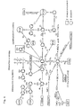
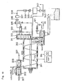
- a thermal decomposition furnace 1 includes a control device 2 for controlling the temperature in the furnace, a recovery device 3 for evaporated metals, furnace reducing means, furnace heating means 20, and cooling means 21, and moreover as a reduced pressure thermal decomposition furnace, enables the recovery of valuables by providing structure and a mechanism for pressure reduction composed of vacuum valves 40 and 42 and the subsequent parts which will be described.
- a sensor group 5 composed of a temperature sensor, a vacuum degree sensor, an oxygen and oxide concentration sensor, and a chlorine and chloride concentration sensor and the like is placed in the thermal decomposition furnace 1, whereby the temperature, the degree of vacuum, the concentration of at least either one of oxygen or oxide gas, and the like in the furnace are measured, and data signals thereof are sent to the control device 2.
- the thermal decomposition furnace 1 is surrounded by a heat insulating material, and a vacuum door 17 which is driven to ascend and descend by an air cylinder or the like is placed in a port for carrying in an object to be treated 18.
- the object to be treated 18 is carried into the furnace while stored in a jig 19 after the vacuum door 17 is opened.
- stirring means 23 for the object to be treated 18 is placed as required in addition to the heating means 20 and the cooling means 21 inside the furnace.
- the stirring means 23 illustrated is a fan, but not limited to this, in place of this or together with this, a screw which gets into the jig 19 to stir the object to be treated 18 may be placed, or a rotary kiln method in which the entire furnace is rotated may be adopted.
- a heater is used as the heating means 20, and a nitrogen gas circulating circuit is used as the cooling means 21.
- a water cooling type cooler 24 for cooling nitrogen gas and a pump 25 for circulating the nitrogen gas in the thermal decomposition furnace 1 are provided in the nitrogen gas circulating circuit 21. It is more preferable that a filter is further provided in the circulating circuit.
- a reducing retort 4 as the furnace reducing means is placed in a produced gas reducing section protruding from the thermal decomposition furnace 1.
- a metal reducing agent such as an aluminum powder or the like alone or together with alkali hydroxide is filled into the reducing retort 4, and a temperature sensor 5a for detecting the temperature in the reducing retort 4 is placed.
- a heater 7 which can heat the interior of the reducing retort 4 to about 800°C to about 1200°C is embedded in a heat insulating material surrounding the reducing retort 4.
- An oxygen concentration sensor 5b and a chlorine concentration sensor 5c are placed in a reducing gas outlet 8 formed downstream of the reducing retort 4.
- the reducing gas outlet 8 leads to the following recovery means 3, and a vacuum door 26 having vacuum-proof performance, which is commonly driven to ascend and descend by a cylinder, is placed midway between them.
- Evaporated substances generated in the thermal decomposition furnace 1 are introduced into the recovery device 3, and the recovery device 3 carries out the function of removing dioxins generated by heating and residual dioxins in the object to be treated 18.
- dioxins are generated in a temperature region not less than 200°C, and dioxins in residual ashes and the like are decomposed when the temperature is 500°C or more.
- Thermal decomposition in the thermal decomposition furnace 1 is normal pressure thermal decomposition in the range of 500°C or thereabouts.
- dioxins in produced gases are decomposed by introducing the produced gases into the reducing retort 4 heated to not less than 500°C, and oxygen and chlorine atoms are dissociated.
- the dissociated oxygen and chlorine immediately react chemically with a metal reducing agent with small reaction energy such as aluminum, magnesium, or the like filled in the reducing retort 4 to thereby be removed, and contribute again to prevent the generation of dioxins.
- heating can be performed after the interior of the furnace is evacuated to about 1 Torr to 10 -2 Torr and the amount of oxygen inside a system is decreased, whereby the consumption of a reducing agent can be reduced.
- the oxygen concentration sensor 5b and the chlorine concentration sensor 5c in the aforethe embodiment are placed not at the reducing gas outlet 8 but inside the thermal decomposition furnace 1, and in the thermal decomposition furnace 1, reducing agent supply means 22 for supplying a powdery, liquid, or gaseous metal reducing agent such as aluminum, magnesium, zinc, or the like into the furnace is provided, and the other structure is the same as in the aforethe first embodiment.
- the concentrations of oxygen, chlorine, and the like in the thermal decomposition furnace 1 are detected and analyzed by the oxygen concentration sensor 5b and the chlorine concentration sensor 5c respectively and exceed predetermined values, for example, the rise of the temperature in the furnace is stopped according to detected values, and simultaneously a metal reducing agent such as aluminum, magnesium, or the like is supplied into the thermal decomposition furnace 1 from the reducing agent supply means 22.
- a metal reducing agent such as aluminum, magnesium, or the like is supplied into the thermal decomposition furnace 1 from the reducing agent supply means 22.
- aluminum oxide, aluminum chloride, or the like is produced, whereby the quantities of oxygen and chlorine and pressure in the thermal decomposition furnace 1 are controlled, preventing the generation of dioxins.
- the recovery means 3 is surrounded by a water-cooled space 27 and has a vacuum door 28 in one side surface from which a recovery retort 29 can be pressed out to the reducing gas outlet 8 through the vacuum door 26 by a cylinder not illustrated even during evaporation operation. Furthermore, the recovery retort 29 can be put in and out by opening and closing the vacuum door 26 during evaporation operation.
- recovered material cooling means 30 mounted in the recovery device 3 is recovered material cooling means 30 by means of nitrogen gas circulation which is the same as in the aforethe thermal decomposition furnace 1, and hence quick cooling of recovered materials is considered.
- a fine particle filter is continuously placed at a stage subsequent to the recovery device 3, and fine particles not recovered in the recovery device 3 are captured.
- the fine particle filter is composed of a wire gauge fine particle filter 31 and an oil fine particle trap 32.
- the oil fine particle trap 32 allows an oil film 35 to capture fine particles by putting up the oil film 35 commonly made of cloth, the lower portion of which is immersed in oil 34, in a case 33 storing the oil 34 in the bottom thereof and forcibly leading gas which has passed the wire gauge fine particle filter 31 to the oil film 35 to let the gas pass.
- the oil 34 rises in the oil film 35 by capillarity to form an oil film, and after capturing fine particles in gas which tries to pass it, falls into the oil 34 together with fine particles.
- the vacuum system branches out into a main line which operates when the degree of vacuum in the thermal decomposition furnace 1 is not more than a predetermined degree of vacuum (10 -3 Torr, for example) and a secondary line which operates when it exceeds the predetermined degree of vacuum.
- the main line is composed of a booster pump 41 and a water sealing pump 47 which are provided through the vacuum valve 40
- the secondary line is composed of a diffusion pump 43 and a rotary pump 44 which are provided through the vacuum valve 42.
- the booster pump 41 and the water sealing pump 47 operate to thereby exhaust gas in the furnace.
- the vacuum valves 40 and 42, and other valves perform opening and closing operation, and the flow of gas shifts from the main line to the secondary line.
- the secondary line is used mainly for recovery of metals, removal of elements, and the like.
- the diffusion pump 43 and the rotary pump 44 of the secondary line operate, and the evaporated substances are recovered while the degree of vacuum in the thermal decomposition furnace 1 is maintained at a degree of vacuum not less than the predetermined degree of vacuum.
- the numeral 45 is a holding pump for assisting the diffusion pump 43 together with the rotary pump 44.
- a chlorine, NOx, SOx, and the like removing device utilizing water circulation of the water sealing pump 47 is placed downstream of the booster pump 41.
- the chlorine and the like removing device includes a water sealing pump water tank 48, a filter 49, an oil-water separating device 50, an alkali feed water tank 51, an ion-exchange resin tank 52, a cooler 53, and a pump 54 in addition to a water sealing pump 47.
- An alkali tank 55 which is commonly a solution tank of calcium hydroxide or sodium hydroxide is connected to the alkali feed water tank 51, and thus water in the alkali feed water tank 51 is circulated in the alkali tank 55 by a pump 56. Therefore, pH-controlled water is sent to the ion-exchange resin tank 52.
- Ion-exchange water from which salt such as sodium chloride or the like is removed by passing through the ion-exchange resin tank 52 is sent into the water sealing vacuum pump 47 by the operation of the pump 54 after being cooled by the cooling water 53.
- Gas is sent into the water sealing vacuum pump 47 from the main line of the vacuum system, and chlorine gas, NOx, SOx, and the like contained in the gas are changed into salt such as calcium salt or sodium salt by chemically reacting with an alkaline solution in the water sealing vacuum pump 47 and then sent to the water sealing pump water tank 48. Part of this salt is removed in the exchange resin tank 52 as described above.
- Gas and a water solution are sent from the water sealing vacuum pump 47 into the water sealing pump water tank 48, where mercury is precipitated and collected in the bottom, and then taken out by timely turning on a cock.
- a gas vent passage 57 including an adsorption device 58 and a pump 59 is provided as an exhaust system in the water sealing pump water tank 48, and gas sucked out by the operation of the pump 59 is introduced into the adsorption device 58.
- the adsorption device 58 contains activated carbon, adsorbent such as zeolite or the like, and a catalyst such as vanadium oxide or the like for decomposing dioxins and the like, and mainly adsorbs and removes noxious components in the gas. The gas from which noxious components are removed in the aforethe manner is exhausted by the operation of the pump 59.
- the concentrations of oxygen and the like and chlorine and the like in the thermal decomposition furnace 1 are detected by the oxygen concentration sensor 5b and the chlorine concentration sensor 5c in the sensor group 5 at the time of thermal decomposition under reduced pressure as described above, and aluminum and aluminum oxide are produced in the thermal decomposition furnace 1 by the reducing agent supply means 22 according to the detected values, whereby the quantities of chlorine and oxygen, and the degree of vacuum are controlled.
- Gases produced in a low temperature range are introduced into the reducing retort 4 and decomposed by heating, and chlorine, oxygen, and the like are removed by being captured by a metal reducing agent or hydroxides of alkali metals and alkali-earth metals there.
- an aluminum powder is suitable for a reducing agent. This is because the aluminum powder is inexpensive, and next to magnesium, it has small reaction energy, whereby it shows oxidation-reduction reaction such as 2O 2 + 3Al ⁇ Al 3 O 4 even in low temperature.
- Gases produced in the thermal decomposition furnace 62 are introduced into the recovery device 3 by opening the vacuum door 26 as described above, and metallic evaporated substances such as cadmium, lead, zinc, chromium, or nickel, water, oil, and the like are condensed and recovered in the recovery retort 29.
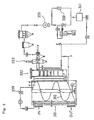
- the thermal decomposition furnace can have triple chamber structure composed of a purge chamber 61 for introducing the object to be treated 18 therein and performing pre-evacuation, a heating chamber 62 including reducing means for performing vacuum heat treatment, and a cooling chamber 63 for cooling a treated matter (See FIG. 4).
- a vacuum heat insulating door system and a vacuum system are provided continuously between the chambers.
- thermal decomposition furnace 62 has such a triple chamber structure, throughput increases and treatment efficiency rises, and unmanned treatment also becomes possible.
- the object 18 to be treated is transferred to the way in/out of the purge chamber 71 by a transfer roller 82, and sent into the purge chamber 71 by a push-in cylinder 83 added to the transfer roller 82 after a vacuum door 71a is opened.
- the object 18 to be treated is returned to the purge chamber 71 after the completion of all treatment.
- the purge chamber 71 serves both as an entrance and an exit of the apparatus.
- a push-out cylinder 84 for pushing out the object 18 to be treated by which the treated object returned to the purge chamber 71 is pushed out to the outside of the chamber, and carried out while being placed on the transfer roller 82.
- a vacuum pump is provided in the purge chamber 71, and substitution of air is performed.
- Vacuum doors 87 and 88 are placed in both side faces of the purge chamber 71, which allows the object to be treated to move between the chambers.
- Bypasses 89 to 99 (The bypass 96 is provided as required.) each including an on-off valve are provided between all the aforethe chambers, which permits the pressures in chambers to be equalized before the vacuum doors between the chambers are opened.
- the preheating chamber 72 is a chamber including heating means for preheating the object to be treated sent from the purge chamber 71 by the transfer conveyor 86 to about a maximum of 150°C commonly, in which as is the case with the aforethe single furnace, the structure of a recovery system, a vacuum system, and an exhaust system including the recovery device 3, the fine particle filter 31, the booster pump 41, the water sealing-type vacuum pump 47 and the following, is provided through the vacuum door 26.
- the structure and operation of these produced gas treating systems and the like are the same as those described above, and thus the explanation thereof is omitted.
- the reducing retort 4 is placed at a gas outlet.
- Vacuum double doors composed of a heat insulating door 100 facing the preheating chamber 72 side and a vacuum door 101 facing the first separating chamber 76 side are placed between the preheating chamber 72 and the first separating chamber 76. Moreover, vacuum double doors composed of a vacuum door 102 facing the first separating chamber 76 side and a heat insulating door 103 facing the first vacuum heating chamber 73 side are placed between the first separating chamber 76 and the first vacuum heating chamber 73 adjacent thereto.
- the first separating chamber 76 includes a push-feed cylinder 104 for transferring the object to be treated sent from the preheating chamber 72 to the first vacuum heating chamber 73.
- the first separating chamber 76 divides the preheating chamber 72 and the first vacuum heating chamber 73, prevents evaporated substances from the preheating chamber 72 from flowing into the first vacuum heating chamber 73, and has a function of regulating the degree of vacuum between the chambers. The evaporated substances are precipitated there, whereby vacuum sealing properties of the vacuum double doors are protected.
- the later separating chambers 77 to 79 also have the same function as the first separating chamber 76. Incidentally, evacuation of the separating chambers 76 to 79 can be performed by the booster pump 41 and the water sealing-type vacuum pump 47 in the previous-stage chamber (the preheating chamber 72 in the case of the first separating chamber 76).
- the first vacuum heating chamber 73 also includes the same structure of a recovery system and a vacuum system as the preheating chamber 72.
- Vacuum double doors composed of a heat insulating door 105 facing the first vacuum heating chamber 73 side and a vacuum door 106 facing the second separating chamber 77 side are placed between the first vacuum heating chamber 73 and the second separating chamber 77.
- the transfer of the object to be treated in the first vacuum heating chamber 73, and therefrom to the second separating chamber 77 is performed by pusher drive by the push-feed cylinder 104, tray pusher, or the like (The transfer progresses by pushes of a plurality of objects to be treated from behind), and the transfer after its entry into the second separating chamber 77 is performed by roller drive.
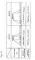
- the first vacuum heating chamber 73 is operated, for example, at a vacuum degree of 600 Torr to 10 -2 Torr and at a temperature between 150°C and 500°C, and thermal decomposition of most of the substances is completed there.
- the produced gases are treated by the furnace reducing agent or the reducing retort 4, oxygen and chlorine are removed therefrom, and moreover the quantities of generation of oxygen and chlorine are controlled by the control of temperature and vacuum degree.
- the above is the same as in the following vacuum heating chambers.
- the second separating chamber 77 includes a push-feed cylinder 107 for sending the object to be treated sent from the first vacuum heating chamber 73 into the second vacuum heating chamber 74.
- Vacuum double doors composed of a vacuum door 108 facing the second separating chamber 77 side and a heat insulating door 109 facing the second vacuum heating chamber 74 side are placed between the second separating chamber 77 and the second vacuum heating chamber 74.
- the second vacuum heating chamber 74 also includes the same structure of a recovery system, a vacuum system, and an exhaust gas system as above.
- the second vacuum heating chamber 74 is operated, for example, at a vacuum degree between about 10 -1 Torr and 10 -3 Torr and at a temperature in the range of 500°C to 900°C and has the aim of fully decomposing and evaporating undecomposed components in a thermally decomposed residue and recovering evaporated metals.
- Vacuum double doors composed of a heat insulating door 110 facing the second vacuum heating chamber 74 side and a vacuum door 111 facing the third separating chamber 78 side are placed between the second vacuum heating chamber 74 and the third separating chamber 78.
- the transfer of the object to be treated in the second vacuum heating chamber 74, and therefrom to the third separating chamber 78 is performed by pusher drive by the push-feed cylinder 107, and the transfer after its entry into the third separating chamber 78 is performed by roller drive.
- the third separating chamber 78 includes a push-feed cylinder 112 for sending the object to be treated sent from the second vacuum heating chamber 74 into the third vacuum heating chamber 75.
- Vacuum double doors composed of a vacuum door 113 facing the third separating chamber 78 side and a heat insulating door 114 facing the third vacuum heating chamber 75 side are placed between the third separating chamber 78 and the third vacuum heating chamber 75.
- the third vacuum heating chamber 75 includes a mechanism in which a diffusion pump 115 and a rotary pump 116 are added to a vacuum system in addition to the same recovery system and vacuum system as the aforethe vacuum heating chamber has. Besides, a heat insulating door 117 facing the fourth separating chamber 79 side is placed between the third vacuum heating chamber 75 and the fourth separating chamber 79. The transfer of the object to be treated in the third vacuum heating chamber 75, and therefrom to the fourth separating chamber 79 is performed by pusher drive by the pusher 112, and its movement in the fourth separating chamber 79 is performed by roller drive.
- the fourth separating chamber 79 serves also as a first vacuum cooling chamber, and includes cooling means for the object to be treated and a push-feed cylinder 118 for sending the object to be treated sent from the third vacuum heating chamber 75 into the second cooling chamber 80.
- a vacuum door 119 is placed between the fourth separating chamber 79 and the second cooling chamber 80 adjacent thereto.
- the recovery device 3, the fine particle filter 31, the booster pump 41, and the rotary pump 116 are disposed through the vacuum door 26, and a bypass passage 120 connecting the downstream side of the vacuum door 26 and the purge chamber 71 is formed.
- the third cooling chamber 81 is placed adjacent to the second cooling chamber 80 with a vacuum door 121 between them, and the cooling chamber 81 adjoins the purge chamber 71 with the vacuum door 88 between them.
- a vacuum pump provided in the bypass passage 120 operates to reduce the pressure in the purge chamber 71. Then, after the pressures in the purge chamber 71 and the pre-heating chamber 72 are equalized by opening the bypass 89, the vacuum door 87 is opened. Subsequently, after the object to be treated is sent into the preheating chamber 72 by the transfer conveyor 86, the vacuum door 87 is closed and the bypass 89 is closed.
- the preheating chamber 72 has, for example, a vacuum degree in the range of 760 Torr to 1 Torr and a temperature between 0°C and 150°C, and decomposition gas generated here and having passed through the reducing retort 4 is led to the recovery device 3 by opening the vacuum door 26, and recovery of evaporated substances, removal of fine particles, and removal of oxygen and chlorine are performed.
- the bypass 90 is opened, and thereby the pressures in the preheating chamber 72 and the first separating chamber 76 are equalized. Subsequently, after the double vacuum doors 100 and 101 are opened and the object to be treated is transferred into the first separating chamber 76 by the transfer conveyor 86, the double vacuum doors 100 and 101 are closed and the bypass 90 is closed.
- the bypass 91 is opened, and the pressures in the first separating chamber 76 and the first vacuum heating chamber 73 are equalized.
- the double vacuum doors 102 and 103 are opened, and the object to be treated is carried into the first vacuum heating chamber 73 by the push-feed cylinder 104.
- heating in a vacuum a vacuum degree of 600 Torr to 10 -2 Torr
- the temperature range of 150°C to 500°C Within this temperature range, most of organic substances and the like are decomposed and evaporated, and passing through the opened vacuum door 26 via the reducing retort 4, recovered in the recovery device 3.
- removal of fine particles and removal of oxygen and chlorine are performed.
- the same operation is performed. More specifically, after the bypass 92 is opened and the pressures in the first vacuum heating chamber 73 and the second separating chamber 77 are equalized, the double vacuum doors 105 and 106 are opened, and the object to be treated is carried into the second separating chamber 77 by the push-feed cylinder 104. Then, after the double vacuum doors 105 and 106 are closed and the bypass 92 is closed, the bypass 93 is opened and the pressures in the second separating chamber 77 and the second vacuum heating chamber 74 are equalized.
- the double vacuum doors 108 and 109 are opened, and the object to be treated is carried into the second vacuum heating chamber 74 by the push-feed cylinder 107, the double vacuum doors 108 and 109 are closed and the bypass 93 is closed.
- the bypasses are opened after the pressures are regulated by using the vacuum pump. The same operation is performed also in the following vacuum heating chambers 74 and 75.
- the second vacuum heating chamber 74 heating in a vacuum (a vacuum degree of 10 -1 Torr to 10 -3 Torr) is performed, for example, in the temperature range of 500°C to 900°C. Within this temperature range, cadmium, zinc, lead, and the like are decomposed and evaporated, and through the opened vacuum door 26, recovered in the recovery device 3. Furthermore, similarly to the above, removal of fine particles and removal of chlorine are performed.
- a vacuum a vacuum degree of 10 -1 Torr to 10 -3 Torr
- the double vacuum doors 110 and 111 are opened, and the object to be treated is transferred into the third separating chamber 78 by the push-feed cylinder 107. Then, after the double vacuum doors 110 and 111 are closed and the bypass 94 is closed, the bypass 95 is opened and the pressures in the third separating chamber 78 and the third vacuum heating chamber 75 are equalized. Subsequently, after the double vacuum doors 113 and 114 are opened, and the object to be treated is transferred into the third vacuum heating chamber 75 by the push-feed cylinder 112, the double vacuum doors 113 and 114 are closed and the bypass 95 is closed.
- heating in a vacuum (a vacuum degree of about 10 -2 Torr to about 10 -5 Torr) is performed, for example, in the temperature range of 900°C to 1300°C.
- a vacuum a vacuum degree of about 10 -2 Torr to about 10 -5 Torr
- copper, tin, chromium, and the like are decomposed and evaporated, and through the opened vacuum door 26, recovered in the recovery device 3.
- removal of fine particles and removal of chlorine are performed.
- the third vacuum heating chamber 75 and the fourth separating chamber 79 always have the same pressure, and after the heat insulating door 117 is opened, the object to be treated is carried into the fourth separating chamber 79 by the push-feed cylinder 112, where temporary cooling of the object to be treated by a vacuum is performed.
- the object to be treated is transferred to the second cooling chamber 80.
- the second cooling chamber 80 residual nitrogen gas in the chamber is exhausted by the operation of the rotary pump 116 and the booster pump 41 while the bypass 120 is closed.
- the bypass 97 is opened and the pressures in the fourth separating chamber 79 and the second cooling chamber 80 are equalized.
- the vacuum door 119 is opened, and the object to be treated is transferred to the second cooling chamber 80 by the push-feed cylinder 118. Thereafter, the vacuum door 119 is closed, and concurrently the bypass 97 is closed.
- the second cooling chamber 80 secondary cooling of the object to be treated by nitrogen gas is performed after nitrogen gas, equal to the amount exhausted, is put back.
- the bypass 98 is opened, and treatment for equalizing the pressures in the second cooling chamber 80 and the third cooling chamber 81 is performed.
- the vacuum door 121 is opened, and the object to be treated is transferred to the third cooling chamber 81 by the transfer conveyor 86. Thereafter, the vacuum door 121 is closed, and simultaneously the bypass 98 is closed, and then cooling by nitrogen is performed in the cooling chamber 81.
- the bypass 99 is opened, and treatment for equalizing the pressures in the third cooling chamber 81 and the purge chamber 71 is performed. Then, the vacuum door 88 is opened, and the object to be treated is carried out to the purge chamber 71 by the transfer conveyor 86. After the vacuum door 88 is closed and the bypass 99 is closed, the purge chamber 71 is returned to its original pressure, the vacuum door 71a is opened, and the treated object is carried out onto the transfer roller 82 by the push-out cylinder 84.
- the third cooling chamber 81 In the third cooling chamber 81, only exchange of nitrogen gas for cooling is performed, and evacuation is not performed. Therefore, treatment time is reduced, and also the cost of installing vacuum system equipment and the quantity of nitrogen gas can be reduced, and thus throughput is increased.
- This treatment apparatus includes a heating device for heating the object to be treated thrown into a closed container, a cooling device, continuous with the heating device, for cooling the heated residue of the object to be treated, means for detecting the concentrations of chlorine, oxygen, and the like in the closed container and controlling the concentrations based on them, means for transferring the object to be treated, and purging means for performing gas substitution in the closed container.
- heating atmosphere gas containing organic halides and substances having organic halide generating capacity is purged with a purge gas immediately after the completion of heat treatment, and the concentrations of the organic halides and the substances having organic halide generating capacity in the treatment container are reduced. Then, the object to be treated is cooled in this state. Thus, the residual concentration of organic halides such as dioxins or the like in the object to be treated can be reduced and removed.
- a purge gas nitrogen, a rare gas such as argon, air, or the like can be used.
- a condition demanded of the purge gas is that it is substantially organic halide-free.
- it is suitable to use a purge gas which can not generate organic halides by reacting with the object to be treated. Since air contains oxygen, when it is used as a purge gas, there is a possibility that organic halides are regenerated during cooling depending on the structure and situation of the heated residue. Accordingly, it is more preferable to use nitrogen or a rare gas.
- it is suitable to reduce the pressure in the container, thereafter perform purge with a purge gas (substitution under reduced pressure), and subsequently perform cooling.
- the means for transferring the object to be treated in the container may be selected according to the form and treatment conditions of the object to be treated.
- a screw conveyor a rotary kiln, a roller house, a tray pusher, a continuous mesh belt, or the like can be used.
- An apparatus used for this substitution treatment under reduced pressure further includes a pressure reducing device for reducing the pressure in the gastight container and a control device for controlling the pressure in the gastight container of the apparatus explained in the aforethe substitution under normal pressure.
- the pressure in the gastight container is reduced to about 10 Torr to 10 -2 Torr by a vacuum pump, and the object to be treated is cooled.
- the cooling of the object to be treated may be performed with the pressure remaining reduced or with the aforethe purge gas being introduced into the gastight container.
- the performance of heat treatment itself of the object to be treated under reduced pressure is more effective in reducing the concentration of organic halides remaining in the heated residue of the object to be treated.
- a purge chamber having a vacuum door at an input port of a hermetic zone including heating means and pressure regulating means. After the object to be treated is introduced into the purge chamber and the interior of the purge chamber is purged by a reduction in pressure or a purge gas, a vacuum door between the purge chamber and the gastight container for heat treatment is opened, and then the object to be treated is introduced into the gastight container.
- a vacuum door between the purge chamber and the gastight container for heat treatment is opened, and then the object to be treated is introduced into the gastight container.
- two connected purge chambers may be provided at a stage prior to a vacuum heating chamber.
- a jig such as a tray or the like capable of coming and going between the two purge chambers and a throwing device for the vacuum heating chamber. It is recommended that the tray come and go between the two purge chambers by transfer means such as a drawer or a pusher.
- the object to be treated may be thrown into the vacuum heating chamber in pieces. It is recommended that the pressure of the purge chamber divided from the gastight container by the vacuum door be reduced and air be purged.
- the heated residue of the object to be treated can be taken out of the gastight container for heat treatment in the same manner. Since cooling of the heated residue demands a lot of time, productivity is raised if the tray is turned.
- a storing chamber capable of gastightly storing the heated residue; a cooling chamber for cooling the heated residue; a purge chamber for purging a purge gas for atmosphere, storing the transfer means for the heated residue such as a tray, a casing, and the like, and performing purge; and a discharge chamber for discharging the heated residue to a conveyor or the like under normal pressure
- These four chambers may include vacuum doors respectively so as to maintain gas tightness independently of one another.
- the heated residue is transferred between these four chambers by moving a jig such as a tray or the like.
- These chambers may be provided in the form of a grid (Each chamber is provided at each vertex of a quadrangle, for example).
- the transfer of the heated residue from the gastight container for performing heat treatment to the storing chamber is performed by various transfer means, and in addition may be performed by providing the storing chamber below the gastight container and dropping the heated residue by gravity.
- the heated residue of the object to be treated heat-treated in the gastight container is moved to the outlet side in the gastight container by a transfer device for objects to be treated provided in the gastight container, and then transferred to the storing chamber placed adjacent to this outlet.
- the tray is waiting in the storing chamber, and the heated residue is stored in this tray. Subsequently, the tray and the casing are moved to the cooling chamber, and the heated residue is cooled as described above. After the heated residue is cooled, the tray is moved to the discharge chamber, and discharged from this discharge chamber to a conveyor and the like.
- the vacant tray from which the heated residue is discharged is returned to the initial storing chamber via the purge chamber for purging air.
- the tray can make the rounds of chambers as described above.
- predetermined treatment can be performed while the plurality of trays are making the rounds of chambers, thereby improving treatment efficiency.
- the movement of the tray between the chambers be performed by the transfer means such as a pusher or a roller. It is also suitable to use a combination of a plurality of transfer means.
- the gases are basically gases produced by heat treatment such as combustion, thermal decomposition, and the like of the object to be treated, but the case where the produced gases contain solid and liquid substances and the like mixed therein is not excluded.
- the produced gases of the object to be treated contain organic halides such as dioxins in many cases, and also contains moisture, oil, metals, and compounds such as metallic oxides resulting from the object to be treated. Such substances need to be decomposed, removed, or recovered before letting out gas into the environment.
- the produced gases of the object to be treated are reformed and decomposed by being heated to about 500°C to about 950°C, or to about 500°C to about 1200°C. It is desirable to perform this treatment in a reducing atmosphere.
- NOx, SOx, and Cl 2 in the produced gases may be removed by an alkali such as NaOH or Ca(OH) 2 .
- a cooling device for cooling the reformed gas by a refrigerant such as water or oil be provided. It is preferable to perform this cooling rapidly so that the residence time of the produced gases at a temperature at which organic halides such as dioxins are produced can be shortened as much as possible.
- the refrigerant is alkaline, an alkali assistant is mixed in the refrigerant, or an alkali is injected in addition to the refrigerant.
- the refrigerant may be injected to the produced gases by a gas injector, a venturi, or the like.
- the produced gases contain dust, and hence it is desirable to provide a filter for removing the dust.
- the cooling device is mounted with a dust filter, an alkali tank, a heat exchanger, a pump, and the like.
- Gas which has passed the cooling device is sent to a recovery device for condensing residual condensates in the gas and recovering them. It is preferable to dispose an adsorption member such as an activated carbon filter or the like, providing for malfunctions, over load, and the like of the aforethe devices for making the produced gases innoxious at a stage prior to the exhaust pump for exhausting gas in the aforethe treatment system.
- an adsorption member such as an activated carbon filter or the like
- the produced gases of the object to be treated are reformed as described above, and sent to the recovery device for condensing and recovering water, oil, evaporated metals, oxides, and the like contained in the produced gases.
- dust removal is performed by a filter, a cyclone, a liquid trap such as an oil trap, or the like for removing dust and the like still remaining in the produced gases.
- a vacuum door and a vacuum valve so that the recovery of condensates, exchange of filters, and the like can be performed during heat treatment of the object to be treated while a space between the recovery device and the dust removing device is maintained gastight.
- the condensates As concerns the taking out of the condensates to the outside of the system, it is preferable to expose the condensates to a non-oxidizing gas after cooling them and before letting them out into the air as described above. This is because the surface zones of the condensates tend to become very large and surface free energy tends to be excessive due to heating under reduced pressure, and thus there are some dangerous cases where strong ignition occurs if the condensates are let out into the air as they are. Specially in the case of metals such as Mg, Al, and the like, there is a possibility that a fire occurs, which is dangerous.
- a gastight container for heating the object to be treated under reduced pressure and a vacuum pump for reducing the pressure in the produced gas treatment system are provided.
- the vacuum pump is selected out of a booster pump, a rotary pump, a water sealing pump, and the like, and that they are combined as required.
- a pump sucking at the back of the vacuum pump may be provided.
- a cooling device for removing organic halides, NOx, SOx, and Cl 2 in the produced gases may be provided. It is preferable to also provide an adsorption device for fail-safe.
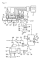
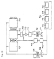
- FIG. 7 is a diagram schematically showing an example of the structure of the treatment apparatus of the present invention.
- This treatment apparatus can heat the object to be treated under almost normal pressure and prevent organic halides such as dioxins from remaining in the heated residue of the object to be treated.
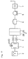
- FIG. 8 is a diagram schematically showing an example of the structure of the treatment apparatus of the present invention.
- This treatment apparatus can heat the object to be treated under reduced pressure and prevent organic halides such as dioxins from remaining in the heated residue of the object to be treated.
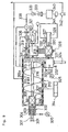
- FIG. 9 is a diagram schematically showing an example of the structure of the treatment apparatus of the present invention.
- This treatment apparatus enables continuous treatment, and an automatic throwing device for the object to be treated and an automatic take-out device for the heated residue are mounted in the reduced pressure-type treatment apparatus illustrated in FIG. 8.
- the normal pressure-type treatment apparatus in FIG. 7 costs less than the reduced pressure-type one.
- the treatment apparatus substitutes a purge gas such as nitrogen for an atmospheric gas containing organic halides after heat-treating the object to be treated, and cools the object to be treated while the concentration of organic halides in the atmosphere is reduced. Thus, the concentration of organic halides remaining in the heated residue can be reduced.
- the object to be treated thrown from an input port 101 into a heat treatment furnace 103 is heated by a heater 105.
- a stirring device not illustrated may be provided to stir an atmosphere in the furnace or to stir the object to be treated.
- the temperature in the furnace is controlled by a control device 110b capable of controlling a temperature sensor 107 and the heater.
- a gas sensor 108 for detecting the gas concentration in the furnace is provided depending on the type of gas which needs to be detected, for example, oxygen concentration, chlorine concentration, or the like.
- Such gas concentration may be regulated by introducing a carrier gas such as nitrogen, a rare gas, or the like.
- a valve in a purge gas introduction system 106 is opened, and a purge gas is introduced to thereby reduce and remove organic halides in the atmospheric gas in the furnace.
- valve in the purge gas introduction system 106 is closed, and a gas cooling device 104 including a filter, a gas cooler, a pump in a bypass is operated to cool the heated residue by a purge gas atmosphere. After cooling is completed, the heated residue of the object to be treated is taken out of an exhaust port 102.
- gases produced by heating are led to a decomposition reaction container 131, where the produced gases let out from the heating furnace 103 are thermally decomposed and reformed by being reheated by the heater. Undecomposed gas is also decomposed.
- a spherical or honeycomb ceramic material, a catalyst, and a reducing agent Zn, Al, Mg, or the like, for example
- an alkali agent for permitting NOx, SOx, Cl 2 , and the like which are decomposition gases to be reacted and removed may be thrown thereinto.
- the aforethe ceramic, catalyst, and reducing agent can be used in combination or individually depending on gas conditions.
- the gas let out from the decomposition reaction container 131 still contains a variety of hydrocarbons. These components condense oil and moisture contained in the produced gases in a condensing device 111.
- Dust and the like are removed from the gas which has passed through the condensing device 111 by a filter 112.
- a vacuum pump 114 such as a rotary pump is provided at a stage next to the filter 112. Gas substitution in the heat treatment furnace 103 only by introduction of a purge gas takes a lot of time, and requires a large amount of purge gas, whereby the quantity of gas to be treated is increased. Hence, it is desirable to first exhaust gas in the heat treatment furnace 103 by the vacuum pump 114, then introduce a purge gas to restore the pressure, and to perform cooling.
- the produced gases of the object to be treated are introduced to a gas heating furnace 115, where undecomposed gas of the produced gases, reproduced dioxins, residual dioxins, and the like are decomposed and reformed at temperatures as high as about 700°C to about 1100°C.
- the gas decomposed and reformed in the gas heating furnace 115 is cooled while being mixed by a cooling device 116 with a gas injector and introduced into a cooling water tank with an oil-water separating tank 118. It is preferable that this cooling is performed as rapidly as possible in order to shorten the residence time of the gas at a dioxin production temperature. For example, it is preferable to perform this cooling within ten seconds. Cooling water is utilized, circulating through an alkali tank 117 for keeping water used for cooling alkaline, a pump, a heat exchanger, and the cooling device 116, in which case NOx, SOx, Cl 2 , and the like in the decomposition gas are also removed by reaction.
- the dust is removed by a filter 119, a bag filter 120, and the like. It is recommended that dust captured by a circulating system of alkaline water be removed by a filter 132.
- a gas adsorption device 121 is further placed at a stage next to the bag filter 120. Gas is exhausted from the back side of the adsorption device 121 by being sucked by a suction pump 122. It is preferable that the exhaust gas is let out after the concentration of noxious components is monitored. Moreover, a bypass for circulating the exhaust gas to the gas heating furnace 115 may be provided.
- the intermediate door 306 is opened, and the vacant jig 304 is returned to the vacuum substitution chamber 302 by the transfer device 307.
- the intermediate door 306 is then closed, and air is brought into the vacuum substitution chamber 302 to restore the pressure to normal pressure.
- the upper door 303 of the vacuum substitution chamber 302 is opened, and the following object to be treated is thrown into the tray 304.
- the object to be treated can be thrown into the heating furnace 310 without air getting into the heating furnace 310.
- the object to be treated thrown into the heating chamber 310 is moved to the treatment outlet side by a screw conveyor 312 while being heated by a heater 311.
- the furnace temperature is controlled by a temperature sensor 313 and a control device 314 for the heater.
- a gas sensor 313a is provided according to the type and content of gas.
- the object to be treated cooled in the cooling chamber 318 is carried out onto the a conveyor 326 by a transfer device 319 after a vacuum door 322 on the outlet side placed in the perpendicular direction is opened.
- the vacuum door 322 is then closed, and pressure reduction by a vacuum pump 320 is performed.
Landscapes
- Engineering & Computer Science (AREA)
- Chemical & Material Sciences (AREA)
- Environmental & Geological Engineering (AREA)
- Chemical Kinetics & Catalysis (AREA)
- Oil, Petroleum & Natural Gas (AREA)
- General Chemical & Material Sciences (AREA)
- Analytical Chemistry (AREA)
- Mechanical Engineering (AREA)
- General Engineering & Computer Science (AREA)
- Life Sciences & Earth Sciences (AREA)
- Soil Sciences (AREA)
- Health & Medical Sciences (AREA)
- Biomedical Technology (AREA)
- Thermal Sciences (AREA)
- Physics & Mathematics (AREA)
- Processing Of Solid Wastes (AREA)
- Fire-Extinguishing Compositions (AREA)
- Treating Waste Gases (AREA)
Applications Claiming Priority (7)
| Application Number | Priority Date | Filing Date | Title |
|---|---|---|---|
| JP10329798 | 1998-03-31 | ||
| JP10329798 | 1998-03-31 | ||
| JP27341798 | 1998-09-28 | ||
| JP27341798 | 1998-09-28 | ||
| JP37717598 | 1998-12-27 | ||
| JP37717598 | 1998-12-27 | ||
| PCT/JP1999/001660 WO1999051366A1 (en) | 1998-03-31 | 1999-03-31 | Method for producing soil, soil-treating unit, method for treating and unit for treating |
Publications (2)
| Publication Number | Publication Date |
|---|---|
| EP1114679A1 true EP1114679A1 (de) | 2001-07-11 |
| EP1114679A4 EP1114679A4 (de) | 2002-09-18 |
Family
ID=27309945
Family Applications (1)
| Application Number | Title | Priority Date | Filing Date |
|---|---|---|---|
| EP99912057A Withdrawn EP1114679A4 (de) | 1998-03-31 | 1999-03-31 | Herstellung von böden, vorrichtung zur behandlung von böden, behandlungsverfahren und vorrichtung |
Country Status (5)
| Country | Link |
|---|---|
| US (2) | US7156027B1 (de) |
| EP (1) | EP1114679A4 (de) |
| JP (1) | JP3395148B2 (de) |
| KR (1) | KR100555686B1 (de) |
| WO (1) | WO1999051366A1 (de) |
Cited By (6)
| Publication number | Priority date | Publication date | Assignee | Title |
|---|---|---|---|---|
| WO2002024354A1 (en) * | 2000-09-22 | 2002-03-28 | Environmental Waste International Inc. | Medical waste treatment unit |
| EP1792667A4 (de) * | 2004-08-25 | 2011-02-23 | Hoei Shokai Co Ltd | Bearbeitungsvorrichtung, bearbeitungsverfahren und verfahren zurerzeugung von entgifteten materialien |
| CN105121602A (zh) * | 2013-05-13 | 2015-12-02 | 三菱重工业株式会社 | 干馏装置 |
| EP2608868A4 (de) * | 2010-08-27 | 2018-01-17 | Empire Technology Development LLC | Vorrichtung zur beseitigung von kohlenwasserstoff |
| CN110293124A (zh) * | 2019-06-22 | 2019-10-01 | 生态环境部华南环境科学研究所 | 一种用于修复农田有机污染土壤的一体化装置 |
| CN114225617A (zh) * | 2021-12-17 | 2022-03-25 | 镇海石化工程股份有限公司 | 高凝点重油油气处理方法 |
Families Citing this family (13)
| Publication number | Priority date | Publication date | Assignee | Title |
|---|---|---|---|---|
| NZ523665A (en) * | 2003-01-15 | 2004-02-27 | Rajeev Prasad Gupta | Use of microwave energy for the combustion of organic material |
| JP4534821B2 (ja) * | 2005-03-18 | 2010-09-01 | 株式会社大林組 | 揮発性有機化合物の浄化システム及び方法 |
| WO2006117005A1 (en) * | 2005-05-03 | 2006-11-09 | Danmarks Tekniske Universitet | Pyrolysis method and apparatus |
| TWI285138B (en) * | 2006-03-29 | 2007-08-11 | Hung Jiang | Method for separating mercury and cracking dioxin and organic substance with high temperature vapor and recycled heat source |
| JP4724052B2 (ja) * | 2006-06-13 | 2011-07-13 | 株式会社東芝 | パッケージ型熱分解処理装置 |
| US7812002B2 (en) * | 2007-03-21 | 2010-10-12 | Quark Pharmaceuticals, Inc. | Oligoribonucleotide inhibitors of NRF2 and methods of use thereof for treatment of cancer |
| ATE550529T1 (de) * | 2008-03-28 | 2012-04-15 | Inergy Automotive Systems Res | Scr-system zur reinigung von abgasen in nox |
| US9939153B2 (en) * | 2013-06-03 | 2018-04-10 | Washington University | Method and apparatus for capturing carbon dioxide during combustion of carbon containing fuel |
| CN108500046A (zh) * | 2018-05-09 | 2018-09-07 | 中国联合工程有限公司 | 污染土壤热脱附装置及其减少二恶英生成的方法 |
| CN109856364A (zh) * | 2019-01-08 | 2019-06-07 | 丁晋利 | 一种土壤检测装置及土壤检测方法 |
| JP6573298B1 (ja) * | 2019-01-22 | 2019-09-11 | 株式会社タクマ | オゾン・プラズマ処理装置及びこれを使用した酸化分解処理方法 |
| CN113883897B (zh) * | 2020-07-01 | 2022-08-16 | 中冶长天国际工程有限责任公司 | 一种链箅机预热段防窜风系统及其风流控制方法 |
| CN112122327B (zh) * | 2020-08-20 | 2022-02-22 | 广州市番禺环境工程有限公司 | 一种基于土壤热解吸修复技术的修复装置 |
Family Cites Families (53)
| Publication number | Priority date | Publication date | Assignee | Title |
|---|---|---|---|---|
| US4685220A (en) * | 1983-09-02 | 1987-08-11 | American Toxic Disposal Partners | Method and apparatus for separating dioxin from fluidizable solids |
| US4615283A (en) * | 1984-09-26 | 1986-10-07 | Westinghouse Electric Corp. | Apparatus and method for disposal of hazardous waste material |
| DE3623492A1 (de) | 1986-07-11 | 1988-01-21 | Hagenmaier Hans Paul | Verfahren zum abbau von halogenierten aromaten |
| US4700638A (en) * | 1986-08-11 | 1987-10-20 | M & S Engineering And Manufacturing Co., Inc. | Method and apparatus for soil detoxification |
| US4667609A (en) * | 1986-09-08 | 1987-05-26 | Robert Hardison | Apparatus and method for treatment of soil contaminated with hydrocarbons |
| NL8700726A (nl) * | 1987-03-27 | 1988-10-17 | Nbm Aannemingsbedrijf Bv | Werkwijze voor het reinigen van verontreinigde grond. |
| US4864942A (en) | 1988-01-14 | 1989-09-12 | Chemical Waste Management Inc. | Process and apparatus for separating organic contaminants from contaminated inert materials |
| US4977839A (en) * | 1988-01-14 | 1990-12-18 | Chemical Waste Management, Inc. | Process and apparatus for separating organic contaminants from contaminated inert materials |
| US4961391A (en) * | 1989-03-29 | 1990-10-09 | International Technology Corporation | Thermal treatment process for organically contaminated material |
| US5020452A (en) * | 1989-10-11 | 1991-06-04 | Murya, Inc. | Thermal remediation apparatus and method |
| FR2653044B1 (fr) | 1989-10-12 | 1992-03-27 | Pec Engineering | Procede et dispositifs de decontamination de produits solides. |
| US5319176A (en) * | 1991-01-24 | 1994-06-07 | Ritchie G. Studer | Plasma arc decomposition of hazardous wastes into vitrified solids and non-hazardous gasses |
| US5103578A (en) * | 1991-03-26 | 1992-04-14 | Amoco Corporation | Method and apparatus for removing volatile organic compounds from soils |
| US5245113A (en) * | 1991-05-23 | 1993-09-14 | Dynecology, Incorporated | Decontamination of PCB contaminated solids |
| US5179903A (en) * | 1991-06-24 | 1993-01-19 | Abboud Harry I | Closed loop incineration process |
| DE4124277A1 (de) * | 1991-07-22 | 1993-01-28 | Linde Ag | Verfahren zur dekontamination von verunreinigten boeden |
| JPH08976B2 (ja) | 1991-08-28 | 1996-01-10 | 株式会社真空技研 | 気相成長装置における真空排気管及びガス導入管の接続装置 |
| JPH05305275A (ja) * | 1991-09-13 | 1993-11-19 | Ogihara:Kk | 真空加熱によるプラスチック等の廃棄物の処理方法および装置 |
| US5230167A (en) | 1991-10-30 | 1993-07-27 | Westinghouse Electric Corp. | Removal or organics and volatile metals from soils using thermal desorption |
| US5273629A (en) * | 1992-02-03 | 1993-12-28 | Recycling Sciences International, Inc. | Method and apparatus for separating contaminants from fluidizable solids and converting the contaminate to less toxic or non-toxic materials |
| JPH05346219A (ja) * | 1992-06-15 | 1993-12-27 | Nkk Corp | 廃棄物の溶融・ガス化装置 |
| US5300137A (en) * | 1992-09-18 | 1994-04-05 | Pittsburgh Mineral And Environmental Technology, Inc. | Method for removing mercury from contaminated soils and industrial wastes and related apparatus |
| TW309448B (de) * | 1993-05-24 | 1997-07-01 | Goal Line Environmental Tech | |
| US5619936A (en) * | 1993-05-28 | 1997-04-15 | Kleen Soil Technologies, L.C. | Thermal desorption unit and processes |
| JP3309257B2 (ja) | 1993-10-18 | 2002-07-29 | 三井造船株式会社 | 集じん灰の処理方法 |
| JP3053045B2 (ja) * | 1993-10-28 | 2000-06-19 | 株式会社クボタ | 流体浄化装置 |
| DK0672743T3 (da) * | 1994-03-18 | 1999-06-23 | Ald Vacuum Techn Gmbh | Fremgangsmåde og apparat til termisk behandling af materialer med andele af forkampelige stoffer |
| JP3095609B2 (ja) * | 1994-03-31 | 2000-10-10 | 日立造船株式会社 | 灰加熱分解装置 |
| JPH07313951A (ja) * | 1994-05-24 | 1995-12-05 | Motoda Electron Co Ltd | 生ゴミ,紙オムツ等の水分を含むか又は悪臭を放つ廃棄物の処理方法 |
| JP2940659B2 (ja) * | 1994-08-30 | 1999-08-25 | 川崎重工業株式会社 | 焼却炉排ガスの処理方法及び装置 |
| JPH08108164A (ja) * | 1994-10-12 | 1996-04-30 | Motoda Electron Co Ltd | ダイオキシンを発生させない塩素を含む合成樹脂廃棄物の熱分解処理方法 |
| JP3731678B2 (ja) * | 1994-11-29 | 2006-01-05 | 株式会社伸生 | 廃棄物の減容処理方法 |
| JPH08168752A (ja) * | 1994-12-15 | 1996-07-02 | Ebara Corp | 土壌中に含まれる芳香族ハロゲン化合物の処理方法 |
| JPH08187483A (ja) * | 1995-01-06 | 1996-07-23 | Motoda Electron Co Ltd | 塩ビ系廃材の無害化処理法及びこの処理における生成物から塩化カルシウムを得る方法 |
| ES2200014T3 (es) * | 1995-01-25 | 2004-03-01 | I.T.B. S.R.L. | Procedimiento y planta para el tratamiento pirotilico de desechos que contienen material organico, en particular para el tratamiento de desechos solidos municipales. |
| JP3218961B2 (ja) * | 1995-02-22 | 2001-10-15 | 三菱マテリアル株式会社 | 含塩素プラスチック廃材の処理方法 |
| DE19606339A1 (de) | 1995-02-22 | 1996-08-29 | Mitsubishi Materials Corp | Verfahren zur Behandlung chlorenthaltender Kunststoffabfälle |
| US5797995A (en) * | 1995-03-29 | 1998-08-25 | General Electric Company | Method for thermal removal of halogenated organic compounds from soil |
| US5662050A (en) * | 1995-05-05 | 1997-09-02 | Angelo, Ii; James F. | Process for chemical/thermal treatment without toxic emissions |
| JPH09126427A (ja) | 1995-10-30 | 1997-05-16 | Motoda Electron Co Ltd | 可燃性廃材の連続熱分解処理方法とその装置 |
| US5886326A (en) * | 1996-01-19 | 1999-03-23 | Thermotrex Corporation | Microwave waste incinerator |
| JP3422616B2 (ja) * | 1996-01-19 | 2003-06-30 | 三菱重工業株式会社 | 汚染土壌の処理方法 |
| JP3382083B2 (ja) | 1996-03-15 | 2003-03-04 | 株式会社東芝 | 処理装置、処理システムおよび処理方法 |
| JP3245073B2 (ja) | 1996-09-30 | 2002-01-07 | 株式会社東芝 | 処理装置および処理方法 |
| WO1997033703A1 (en) * | 1996-03-15 | 1997-09-18 | Ogihara Ecology Co., Ltd. | Treatment apparatus, treatment system and treatment method |
| US5720232A (en) * | 1996-07-10 | 1998-02-24 | Meador; William R. | Method and apparatus for recovering constituents from discarded tires |
| WO1998005439A1 (en) | 1996-08-01 | 1998-02-12 | Itochu Shoji Kabushikikaisha | Method of thermal decomposition of scrap motor vehicle and apparatus therefor |
| JPH1047629A (ja) * | 1996-08-01 | 1998-02-20 | Kawasaki Steel Corp | シュレッダ・ダストの熱分解処理方法及び装置 |
| US5836718A (en) * | 1997-01-13 | 1998-11-17 | Price; Philip A. | Method and apparatus for ex situ cleaning of contaminated soil |
| US6063979A (en) * | 1997-01-30 | 2000-05-16 | Kurita Water Industries Ltd. | Method of decomposing dioxins |
| JP3763557B2 (ja) | 1997-07-04 | 2006-04-05 | コスモリード株式会社 | 真空蒸発分離回収方法及び装置 |
| DE69833204T2 (de) * | 1998-09-04 | 2006-09-21 | Maejima, Fumio | Verbrennungsanlage zur entfernung von schadstoffen |
| US6284940B1 (en) * | 1999-06-07 | 2001-09-04 | Kurita Water Industries Ltd. | Method for decomposing halogenated organic compound |
-
1999
- 1999-03-31 WO PCT/JP1999/001660 patent/WO1999051366A1/ja not_active Ceased
- 1999-03-31 JP JP2000542123A patent/JP3395148B2/ja not_active Expired - Fee Related
- 1999-03-31 KR KR1020007010691A patent/KR100555686B1/ko not_active Expired - Fee Related
- 1999-03-31 EP EP99912057A patent/EP1114679A4/de not_active Withdrawn
-
2000
- 2000-09-29 US US09/676,367 patent/US7156027B1/en not_active Expired - Fee Related
-
2006
- 2006-08-25 US US11/509,586 patent/US20060293551A1/en not_active Abandoned
Cited By (11)
| Publication number | Priority date | Publication date | Assignee | Title |
|---|---|---|---|---|
| WO2002024354A1 (en) * | 2000-09-22 | 2002-03-28 | Environmental Waste International Inc. | Medical waste treatment unit |
| US7361303B2 (en) | 2000-09-22 | 2008-04-22 | Environmental Waste International Inc. | Medical waste treatment unit |
| EP1700610A3 (de) * | 2000-09-22 | 2014-05-14 | Environmental Waste International Inc. | Vorrichtung zur Behandlung von medizinischen Abfällen |
| EP1792667A4 (de) * | 2004-08-25 | 2011-02-23 | Hoei Shokai Co Ltd | Bearbeitungsvorrichtung, bearbeitungsverfahren und verfahren zurerzeugung von entgifteten materialien |
| EP2608868A4 (de) * | 2010-08-27 | 2018-01-17 | Empire Technology Development LLC | Vorrichtung zur beseitigung von kohlenwasserstoff |
| CN105121602A (zh) * | 2013-05-13 | 2015-12-02 | 三菱重工业株式会社 | 干馏装置 |
| CN105121602B (zh) * | 2013-05-13 | 2017-04-26 | 三菱重工业株式会社 | 干馏装置 |
| CN110293124A (zh) * | 2019-06-22 | 2019-10-01 | 生态环境部华南环境科学研究所 | 一种用于修复农田有机污染土壤的一体化装置 |
| CN110293124B (zh) * | 2019-06-22 | 2021-03-09 | 生态环境部华南环境科学研究所 | 一种用于修复农田有机污染土壤的一体化装置 |
| CN114225617A (zh) * | 2021-12-17 | 2022-03-25 | 镇海石化工程股份有限公司 | 高凝点重油油气处理方法 |
| CN114225617B (zh) * | 2021-12-17 | 2023-09-08 | 镇海石化工程股份有限公司 | 高凝点重油油气处理方法 |
Also Published As
| Publication number | Publication date |
|---|---|
| KR20010042202A (ko) | 2001-05-25 |
| WO1999051366A1 (en) | 1999-10-14 |
| JP3395148B2 (ja) | 2003-04-07 |
| US20060293551A1 (en) | 2006-12-28 |
| EP1114679A4 (de) | 2002-09-18 |
| KR100555686B1 (ko) | 2006-03-03 |
| US7156027B1 (en) | 2007-01-02 |
Similar Documents
| Publication | Publication Date | Title |
|---|---|---|
| US7156027B1 (en) | Method for producing soil, soil-processing unit, method for processing and unit for processing | |
| KR100583892B1 (ko) | 처리장치, 처리방법 및 토양의 처리방법 | |
| JPWO1999051366A1 (ja) | 土壌の生産方法、土壌処理装置、処理方法および処理装置 | |
| KR101721614B1 (ko) | 시멘트 킬른 배기가스의 처리장치 및 처리 방법 | |
| TW457140B (en) | Apparatus, system and method for treating waste material | |
| CN1070839A (zh) | 净化油燃烧设备排出的有负载的废气的方法 | |
| JPH06506246A (ja) | 環境に害を与える固体物の熱分解処理用装置 | |
| US5602297A (en) | Multistage double closed-loop process for waste decontamination | |
| JPH11114374A (ja) | 活性炭循環バグフィルタで用いられた活性炭の再生方法 | |
| JP2007039296A (ja) | セメント製造装置の排ガスの処理方法及び処理システム | |
| KR101660469B1 (ko) | 수은 함유 폐기물의 처리 장치 및 이러한 장치를 사용한 고순도 원소 수은의 회수 방법 | |
| JP2007196229A (ja) | 処理装置 | |
| JP2002331273A (ja) | 処理方法及び処理装置 | |
| JP2003175372A (ja) | 土壌の生産方法、土壌処理装置、処理方法および処理装置 | |
| JP3023479B1 (ja) | 処理装置、処理方法および土壌の処理方法 | |
| JP4675804B2 (ja) | ポリ塩化ビフェニル汚染物の処理設備 | |
| EP1015143B1 (de) | Behandlung von verunreinigten böden | |
| WO1992019365A1 (en) | Stack gas cleaning process | |
| JP3310245B2 (ja) | 処理装置および処理方法 | |
| JP2007152350A (ja) | 処理装置及び処理方法 | |
| JP3818936B2 (ja) | 処理装置 | |
| JP3966485B2 (ja) | 塩素化合物を含有する廃棄物の焼却処分過程において生じる排ガスの処理方法およびその装置 | |
| JP2002194451A (ja) | 処理システムおよび処理方法 | |
| RU2113874C1 (ru) | Способ уничтожения высокотоксичных органических соединений | |
| JP4160065B2 (ja) | 土壌の処理装置 |
Legal Events
| Date | Code | Title | Description |
|---|---|---|---|
| PUAI | Public reference made under article 153(3) epc to a published international application that has entered the european phase |
Free format text: ORIGINAL CODE: 0009012 |
|
| 17P | Request for examination filed |
Effective date: 20001027 |
|
| AK | Designated contracting states |
Kind code of ref document: A1 Designated state(s): BE DE DK FI FR GB NL SE |
|
| A4 | Supplementary search report drawn up and despatched |
Effective date: 20020806 |
|
| AK | Designated contracting states |
Kind code of ref document: A4 Designated state(s): BE DE DK FI FR GB NL SE |
|
| RIC1 | Information provided on ipc code assigned before grant |
Free format text: 7B 09B 3/00 A, 7B 09C 1/06 B, 7B 01D 53/34 B, 7F 23G 7/14 B, 7B 01D 53/70 B |
|
| 17Q | First examination report despatched |
Effective date: 20031209 |
|
| STAA | Information on the status of an ep patent application or granted ep patent |
Free format text: STATUS: THE APPLICATION IS DEEMED TO BE WITHDRAWN |
|
| 18D | Application deemed to be withdrawn |
Effective date: 20101001 |