EP1114785B1 - Ensemble de séparation à lame - Google Patents
Ensemble de séparation à lame Download PDFInfo
- Publication number
- EP1114785B1 EP1114785B1 EP00127382A EP00127382A EP1114785B1 EP 1114785 B1 EP1114785 B1 EP 1114785B1 EP 00127382 A EP00127382 A EP 00127382A EP 00127382 A EP00127382 A EP 00127382A EP 1114785 B1 EP1114785 B1 EP 1114785B1
- Authority
- EP
- European Patent Office
- Prior art keywords
- stripper
- blade
- blade assembly
- recited
- rotatable shaft
- Prior art date
- Legal status (The legal status is an assumption and is not a legal conclusion. Google has not performed a legal analysis and makes no representation as to the accuracy of the status listed.)
- Expired - Lifetime
Links
- 239000000463 material Substances 0.000 claims description 12
- 238000000034 method Methods 0.000 claims description 8
- 229920002799 BoPET Polymers 0.000 claims description 2
- 229920000728 polyester Polymers 0.000 claims description 2
- 239000000853 adhesive Substances 0.000 description 3
- 230000001070 adhesive effect Effects 0.000 description 3
- 239000004033 plastic Substances 0.000 description 2
- 239000005041 Mylar™ Substances 0.000 description 1
- 230000004323 axial length Effects 0.000 description 1
- 239000003795 chemical substances by application Substances 0.000 description 1
- 230000001419 dependent effect Effects 0.000 description 1
- 239000003000 extruded plastic Substances 0.000 description 1
- 238000010137 moulding (plastic) Methods 0.000 description 1
- 239000000758 substrate Substances 0.000 description 1
- 230000007704 transition Effects 0.000 description 1
Images


Classifications
-
- B—PERFORMING OPERATIONS; TRANSPORTING
- B41—PRINTING; LINING MACHINES; TYPEWRITERS; STAMPS
- B41J—TYPEWRITERS; SELECTIVE PRINTING MECHANISMS, i.e. MECHANISMS PRINTING OTHERWISE THAN FROM A FORME; CORRECTION OF TYPOGRAPHICAL ERRORS
- B41J2/00—Typewriters or selective printing mechanisms characterised by the printing or marking process for which they are designed
- B41J2/005—Typewriters or selective printing mechanisms characterised by the printing or marking process for which they are designed characterised by bringing liquid or particles selectively into contact with a printing material
- B41J2/01—Ink jet
-
- B—PERFORMING OPERATIONS; TRANSPORTING
- B65—CONVEYING; PACKING; STORING; HANDLING THIN OR FILAMENTARY MATERIAL
- B65H—HANDLING THIN OR FILAMENTARY MATERIAL, e.g. SHEETS, WEBS, CABLES
- B65H29/00—Delivering or advancing articles from machines; Advancing articles to or into piles
- B65H29/54—Article strippers, e.g. for stripping from advancing elements
- B65H29/56—Article strippers, e.g. for stripping from advancing elements for stripping from elements or machines
-
- B—PERFORMING OPERATIONS; TRANSPORTING
- B41—PRINTING; LINING MACHINES; TYPEWRITERS; STAMPS
- B41J—TYPEWRITERS; SELECTIVE PRINTING MECHANISMS, i.e. MECHANISMS PRINTING OTHERWISE THAN FROM A FORME; CORRECTION OF TYPOGRAPHICAL ERRORS
- B41J2/00—Typewriters or selective printing mechanisms characterised by the printing or marking process for which they are designed
- B41J2/005—Typewriters or selective printing mechanisms characterised by the printing or marking process for which they are designed characterised by bringing liquid or particles selectively into contact with a printing material
- B41J2/01—Ink jet
- B41J2002/012—Ink jet with intermediate transfer member
-
- B—PERFORMING OPERATIONS; TRANSPORTING
- B65—CONVEYING; PACKING; STORING; HANDLING THIN OR FILAMENTARY MATERIAL
- B65H—HANDLING THIN OR FILAMENTARY MATERIAL, e.g. SHEETS, WEBS, CABLES
- B65H2401/00—Materials used for the handling apparatus or parts thereof; Properties thereof
- B65H2401/10—Materials
- B65H2401/11—Polymer compositions
- B65H2401/114—Polyester, e.g. polyethylene terephthalate [PET]
-
- B—PERFORMING OPERATIONS; TRANSPORTING
- B65—CONVEYING; PACKING; STORING; HANDLING THIN OR FILAMENTARY MATERIAL
- B65H—HANDLING THIN OR FILAMENTARY MATERIAL, e.g. SHEETS, WEBS, CABLES
- B65H2402/00—Constructional details of the handling apparatus
- B65H2402/50—Machine elements
- B65H2402/51—Joints, e.g. riveted or magnetic joints
-
- Y—GENERAL TAGGING OF NEW TECHNOLOGICAL DEVELOPMENTS; GENERAL TAGGING OF CROSS-SECTIONAL TECHNOLOGIES SPANNING OVER SEVERAL SECTIONS OF THE IPC; TECHNICAL SUBJECTS COVERED BY FORMER USPC CROSS-REFERENCE ART COLLECTIONS [XRACs] AND DIGESTS
- Y10—TECHNICAL SUBJECTS COVERED BY FORMER USPC
- Y10S—TECHNICAL SUBJECTS COVERED BY FORMER USPC CROSS-REFERENCE ART COLLECTIONS [XRACs] AND DIGESTS
- Y10S271/00—Sheet feeding or delivering
- Y10S271/90—Stripper
Definitions
- the present invention relates to ink jet offset printers, and more particularly to a stripper blade assembly for removing a print medium from the surface of an offset drum in an ink jet offset printer.
- an intermediate image is printed onto a print surface of a drum, the print surface generally being a release agent coated on the surface of the drum.
- the intermediate image is then transferred from the print surface onto a print medium, such as paper or transparency material, in a transfer fusing process.
- a transfer fusing process causes the print medium to tend to adhere to the surface of the drum.
- the print medium is stripped from the drum with multiple, spring loaded, plastic fingers that are presented to the drum and print medium at a specified time in the print process.
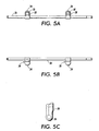
- the blade holder 24 has a main body 36 with a top surface 38 and a bottom surface 40.
- the thin blade 22 is fixedly attached to the top surface 38 along a leading edge 42 via a suitable adhesive 44 that is compatible with the materials of both the blade holder 24 and the thin blade.
- a leading edge 46 of the thin blade 22 extends beyond the leading edge 42 of the top surface 38 of the blade holder 24 .
- the adhesive 44 may be in the form of a double-sided sticky tape.
- the top surface 38 also includes a longitudinal ledge 48.
- the thin blade 22 includes a corresponding longitudinal bend 50 that overhangs the ledge 48 to provide a smooth transition of the medium path 18 over the top of the blade holder 24 .
- the guide ribs 30 of the blade holder 24 engage the shaft 26 via the slots, and the blade holder is rotated until the flexible eyelet portions 32 snap over the protuberances 34 of the connectors 28 to secure the blade holder to the shaft.
- the stripper blade assembly 20 is generally kept clear of the drum 12, but when the print medium passes through the transfer nip 16, the shaft 26 rotates to bring the thin blade 22 in contact with the drum 12 along the width of the drum to detach the leading edge of the print medium from the drum. Alternatively the entire assembly 20 may be moved linearly to bring the thin blade 22 in contact with the drum 12.
- the stripper blade assembly 20 then moves away from the drum and the print medium passes over the blade holder 24 to exit the printer along the medium path 18.
- the flexible eyelet portions 32 are lifted from the protuberances 34 and the body 36 is rotated to clear the connectors 28.
- the blade holder 24 is then pulled back from the shaft 26, disengaging the guide ribs 30 from the shaft, to complete the removal.
- the material of the thin blade 22 needs to be flexible, but durable; needs to be compatible with the ink chemistry of the printer, as vapor from the ink is present; and needs to be heat resistant.
- a material includes a Mylar/polyester material that may be (0.007") 0.18 mm thick, 221 mm (8.75") long and 28mm (1.1") wide.
- the bend 50 in the thin blade material is formed thermally to provide a smooth bend in order to avoid any sharp edges that might scrape the ink surface of the print medium.
- the material of blade holder 24, which may be an extruded plastic molding needs to have dimensional stability and be moldable; needs to be compatible with the ink chemistry of the printer; and needs to be heat resistant.
- the materials of the thin blade 22 and the blade holder 24 need to be compatible with the adhesive 44 used to assure a secure attachment of the thin blade to the blade holder.
- the present invention provides a stripper blade assembly 20 for an ink jet offset printer that has a thin blade 22 fixedly attached to a blade holder 24 that in turn may be removably attached to a shaft 26, which at the appropriate point in the print process engages the drum 12 along its axial length to strip the leading edge of the print medium from the surface of the drum while minimizing damage to the drum or medium and reducing the risk of jams.
Landscapes
- Engineering & Computer Science (AREA)
- Mechanical Engineering (AREA)
- Ink Jet (AREA)
- Separation, Sorting, Adjustment, Or Bending Of Sheets To Be Conveyed (AREA)
- Handling Of Sheets (AREA)
Claims (10)
- Ensemble de séparation à lame (20) pour une imprimante à jet d'encre ayant un tambour déporté (12) comprenant :caractérisé en ce que la lame fine comprend un morceau rectangulaire mince de matériau flexible ayant un bord d'attaque longitudinal et ayant une courbure longitudinale vers un bord arrière en face du bord d'attaque.un arbre de séparateur (26) ;un porte lame (24) monté sur l'arbre de séparateur ;une lame fine (22) montée de façon fixe sur le porte lame de telle façon que, lorsqu'elle est en contact avec le tambour en un point approprié dans un processus d'impression, la lame fine s'engage entièrement dans le bord d'attaque d'un milieu d'impression sur le tambour déporté pour séparer le milieu d'impression du tambour déporté.
- Ensemble de séparation à lame selon la revendication 1, dans lequel l'arbre de séparateur comprend :un arbre rotatif ; etun connecteur mécanique (28) attaché de façon fixe à l'arbre rotatif.
- Ensemble de séparation à lame selon la revendication 2, dans lequel le porte lame (24) comprend :un corps ayant une surface supérieure (38) et une surface inférieure (40), la lame fine étant attachée de façon fixe à la surface supérieure ; etun moyen (32) monté de façon fixe sur la surface inférieure pour attacher de façon détachable le corps au connecteur mécanique (28) sur l'arbre rotatif.
- Ensemble de séparation à lame selon la revendication 3, dans lequel le corps comprend de plus une pluralité de nervures (30), chacune ayant une fente, montée de façon fixe sur la surface inférieure (40) pour interagir avec l'arbre rotatif lorsque le corps est attaché à l'arbre rotatif.
- Ensemble de séparation à lame selon la revendication 4, dans lequel le corps comprend de plus un moyen de guide (56) attaché de façon fixe à la surface inférieure (40) pour guider le moyen d'attache détachable (32) pour interagir avec le connecteur mécanique (28) pour fixer le corps sur l'arbre rotatif.
- Ensemble de séparation à lame selon la revendication 3, comprenant de plus un moyen (44) pour attacher de façon fixe la lame fine (22) à la surface supérieure (38) du corps.
- Ensemble de séparation à lame selon la revendication 6, dans lequel le moyen d'attache de façon fixe comprend une bande adhésive à double face.
- Ensemble de séparation à lame selon la revendication 1, dans lequel le matériau de la lame fine comprend un Mylar®/matériau polyester.
- Ensemble de séparation à lame selon la revendication 1, dans lequel l'épaisseur du bord de la lame fine est de 0,18 mm (0,007 pouce).
- Ensemble de séparation à lame selon la revendication 2, dans lequel le connecteur mécanique (28) est surmoulé sur l'arbre rotatif pour attacher de façon fixe le connecteur mécanique à l'arbre rotatif.
Applications Claiming Priority (2)
| Application Number | Priority Date | Filing Date | Title |
|---|---|---|---|
| US465240 | 1999-12-15 | ||
| US09/465,240 US6293545B1 (en) | 1999-12-15 | 1999-12-15 | Stripper blade assembly |
Publications (3)
| Publication Number | Publication Date |
|---|---|
| EP1114785A2 EP1114785A2 (fr) | 2001-07-11 |
| EP1114785A3 EP1114785A3 (fr) | 2002-10-09 |
| EP1114785B1 true EP1114785B1 (fr) | 2004-08-25 |
Family
ID=23846995
Family Applications (1)
| Application Number | Title | Priority Date | Filing Date |
|---|---|---|---|
| EP00127382A Expired - Lifetime EP1114785B1 (fr) | 1999-12-15 | 2000-12-13 | Ensemble de séparation à lame |
Country Status (4)
| Country | Link |
|---|---|
| US (1) | US6293545B1 (fr) |
| EP (1) | EP1114785B1 (fr) |
| JP (1) | JP2001199607A (fr) |
| DE (1) | DE60013238T2 (fr) |
Families Citing this family (10)
| Publication number | Priority date | Publication date | Assignee | Title |
|---|---|---|---|---|
| JP2001260446A (ja) * | 2000-01-12 | 2001-09-25 | Fuji Photo Film Co Ltd | 記録装置およびその方法、およびこの装置に用いられる剥離爪 |
| KR100433554B1 (ko) * | 2002-07-23 | 2004-05-31 | 삼성전자주식회사 | 인쇄기의 정착장치 |
| US6766896B1 (en) * | 2003-03-27 | 2004-07-27 | China Steel Corporation | Scraping device |
| US6986575B1 (en) * | 2004-06-30 | 2006-01-17 | Xerox Corporation | Automatic rotating media stripper carriage for a printer and method for maintaining a printer |
| US20070206981A1 (en) * | 2006-03-01 | 2007-09-06 | Xerox Corporation | Fusing apparatus including a sheet centering stripper assembly |
| US20110221841A1 (en) * | 2010-03-09 | 2011-09-15 | Xerox Corporation | Stripping blade for stripping media from a drum in an inkjet printer |
| US8313190B2 (en) * | 2010-03-11 | 2012-11-20 | Xerox Corporation | System and method for stripping media from an offset imaging member in an inkjet printer |
| US8695503B2 (en) | 2011-08-31 | 2014-04-15 | Xerox Corporation | Apparatus and method for locking and actuating a stripper blade in a printer |
| JP5999053B2 (ja) * | 2013-09-09 | 2016-09-28 | 富士ゼロックス株式会社 | 剥離機構、画像形成ユニットおよび画像形成装置 |
| DE102014006253A1 (de) * | 2014-04-28 | 2015-10-29 | Giesecke & Devrient Gmbh | Abstreifeinrichtung |
Family Cites Families (15)
| Publication number | Priority date | Publication date | Assignee | Title |
|---|---|---|---|---|
| BR7503982A (pt) * | 1974-06-26 | 1976-07-06 | Roland Offsetmaschf | Caixa de tinta aperfeicoada em um mecanismo tintureiro para maquinas impressoras |
| US4119308A (en) * | 1977-06-20 | 1978-10-10 | Xerox Corporation | Sheet stripping apparatus |
| JPS5538310A (en) * | 1978-09-11 | 1980-03-17 | Nat Starch Chem Corp | Aerosol hair spray composition |
| US4387981A (en) * | 1980-12-23 | 1983-06-14 | Nashua Corporation | Sheet stripping apparatus and method |
| JPS57122466A (en) * | 1981-01-23 | 1982-07-30 | Fuji Xerox Co Ltd | Peeling claw of sheet |
| JPS5895768A (ja) * | 1981-12-02 | 1983-06-07 | Copyer Co Ltd | 電子複写機に於けるマイラ−分離機構 |
| JPS59118544A (ja) * | 1982-12-25 | 1984-07-09 | Koito Mfg Co Ltd | 車輌用前照灯の光軸調整装置 |
| JPS61145958A (ja) * | 1984-12-19 | 1986-07-03 | Dainippon Printing Co Ltd | 光フアイバによる投受光装置 |
| JPS62215974A (ja) * | 1986-03-18 | 1987-09-22 | Toshiba Corp | 画像形成装置 |
| US5455604A (en) * | 1991-04-29 | 1995-10-03 | Tektronix, Inc. | Ink jet printer architecture and method |
| DE4405197C2 (de) * | 1994-02-18 | 1996-10-02 | Santrade Ltd | Vorrichtung zum Ablösen eines Produktes von einem endlos umlaufenden Band |
| DE4440648A1 (de) * | 1994-11-14 | 1996-05-15 | Windmoeller & Hoelscher | Rakelvorrichtung für Tiefdruckmaschinen |
| EP0782968B1 (fr) * | 1995-12-18 | 2001-10-17 | Heidelberger Druckmaschinen Aktiengesellschaft | Méthode et appareils pour maintenir des substrats sur une bande transporteuse d'une machine d'impression |
| DE69720205T2 (de) * | 1996-12-18 | 2003-09-25 | Toshiba Tec K.K., Tokio/Tokyo | Tintenstrahldrucker |
| JP3987166B2 (ja) * | 1997-08-21 | 2007-10-03 | 株式会社不二工機 | 温度式サブクール制御弁 |
-
1999
- 1999-12-15 US US09/465,240 patent/US6293545B1/en not_active Expired - Lifetime
-
2000
- 2000-11-22 JP JP2000355098A patent/JP2001199607A/ja active Pending
- 2000-12-13 DE DE60013238T patent/DE60013238T2/de not_active Expired - Lifetime
- 2000-12-13 EP EP00127382A patent/EP1114785B1/fr not_active Expired - Lifetime
Also Published As
| Publication number | Publication date |
|---|---|
| DE60013238D1 (de) | 2004-09-30 |
| US6293545B1 (en) | 2001-09-25 |
| JP2001199607A (ja) | 2001-07-24 |
| DE60013238T2 (de) | 2004-12-30 |
| EP1114785A2 (fr) | 2001-07-11 |
| EP1114785A3 (fr) | 2002-10-09 |
Similar Documents
| Publication | Publication Date | Title |
|---|---|---|
| EP0822093B1 (fr) | Feuille de nettoyage sensible à la pression et méthode de nettoyage d'un dispositif de formation d'image | |
| EP1114785B1 (fr) | Ensemble de séparation à lame | |
| US20250144930A1 (en) | Arrangements for securing cylinder jackets | |
| US5120147A (en) | Printing device | |
| EP0622242B1 (fr) | Appareil pour l'impression d'images graphiques | |
| US7552920B2 (en) | Paper feed cassette | |
| EP2052866B1 (fr) | Appareil d'impression | |
| EP1993844B1 (fr) | Cassette et imprimante | |
| KR101712404B1 (ko) | 재접착식 메모지용 프린터 | |
| CN211617073U (zh) | 标签打印机 | |
| JP2001106216A (ja) | ラベル発行装置 | |
| EP0225498B1 (fr) | Assemblage d'imprimante à ruban encreur avec une protection intégrale de ruban encreur et méthode d'impression de document | |
| JP3059623U (ja) | 用 紙 | |
| US5735616A (en) | Printing mechanism with means for preventing contact between ink ribbon and drive IC of thermal head | |
| CN116373462B (zh) | 一种支承组件、耗材单元、打印机芯和打印装置 | |
| GB2311495A (en) | Pre-print sheet cleaning apparatus for thermal printer | |
| US20240265829A1 (en) | Printing medium and tape cartridge | |
| CN120363613A (zh) | 卷筒纸支架及打印机 | |
| KR20050077360A (ko) | 2 가지 방식의 용지 픽업 시스템 | |
| JP4256154B2 (ja) | 熱転写プリンタ | |
| CN1939825A (zh) | 具有手动进纸盘的成像设备 | |
| JPH03254968A (ja) | シリアルプリンタ用印刷用紙搬送機構 | |
| JPH10157897A (ja) | プリンタの用紙ガイド機構 | |
| JPH11322108A (ja) | 用紙のガイド機構 | |
| JPH04255376A (ja) | プリンタ |
Legal Events
| Date | Code | Title | Description |
|---|---|---|---|
| PUAI | Public reference made under article 153(3) epc to a published international application that has entered the european phase |
Free format text: ORIGINAL CODE: 0009012 |
|
| AK | Designated contracting states |
Kind code of ref document: A2 Designated state(s): AT BE CH CY DE DK ES FI FR GB GR IE IT LI LU MC NL PT SE TR |
|
| AX | Request for extension of the european patent |
Free format text: AL;LT;LV;MK;RO;SI |
|
| PUAL | Search report despatched |
Free format text: ORIGINAL CODE: 0009013 |
|
| AK | Designated contracting states |
Kind code of ref document: A3 Designated state(s): AT BE CH CY DE DK ES FI FR GB GR IE IT LI LU MC NL PT SE TR |
|
| AX | Request for extension of the european patent |
Free format text: AL;LT;LV;MK;RO;SI |
|
| 17P | Request for examination filed |
Effective date: 20030409 |
|
| AKX | Designation fees paid |
Designated state(s): DE FR GB |
|
| 17Q | First examination report despatched |
Effective date: 20030703 |
|
| GRAP | Despatch of communication of intention to grant a patent |
Free format text: ORIGINAL CODE: EPIDOSNIGR1 |
|
| GRAS | Grant fee paid |
Free format text: ORIGINAL CODE: EPIDOSNIGR3 |
|
| GRAA | (expected) grant |
Free format text: ORIGINAL CODE: 0009210 |
|
| AK | Designated contracting states |
Kind code of ref document: B1 Designated state(s): DE FR GB |
|
| REG | Reference to a national code |
Ref country code: GB Ref legal event code: FG4D |
|
| REG | Reference to a national code |
Ref country code: IE Ref legal event code: FG4D |
|
| REF | Corresponds to: |
Ref document number: 60013238 Country of ref document: DE Date of ref document: 20040930 Kind code of ref document: P |
|
| ET | Fr: translation filed | ||
| PLBE | No opposition filed within time limit |
Free format text: ORIGINAL CODE: 0009261 |
|
| STAA | Information on the status of an ep patent application or granted ep patent |
Free format text: STATUS: NO OPPOSITION FILED WITHIN TIME LIMIT |
|
| 26N | No opposition filed |
Effective date: 20050526 |
|
| REG | Reference to a national code |
Ref country code: GB Ref legal event code: 746 Effective date: 20050809 |
|
| REG | Reference to a national code |
Ref country code: FR Ref legal event code: PLFP Year of fee payment: 16 |
|
| REG | Reference to a national code |
Ref country code: FR Ref legal event code: PLFP Year of fee payment: 17 |
|
| PGFP | Annual fee paid to national office [announced via postgrant information from national office to epo] |
Ref country code: DE Payment date: 20161121 Year of fee payment: 17 Ref country code: GB Payment date: 20161128 Year of fee payment: 17 Ref country code: FR Payment date: 20161121 Year of fee payment: 17 |
|
| REG | Reference to a national code |
Ref country code: DE Ref legal event code: R119 Ref document number: 60013238 Country of ref document: DE |
|
| GBPC | Gb: european patent ceased through non-payment of renewal fee |
Effective date: 20171213 |
|
| REG | Reference to a national code |
Ref country code: FR Ref legal event code: ST Effective date: 20180831 |
|
| PG25 | Lapsed in a contracting state [announced via postgrant information from national office to epo] |
Ref country code: FR Free format text: LAPSE BECAUSE OF NON-PAYMENT OF DUE FEES Effective date: 20180102 Ref country code: DE Free format text: LAPSE BECAUSE OF NON-PAYMENT OF DUE FEES Effective date: 20180703 |
|
| PG25 | Lapsed in a contracting state [announced via postgrant information from national office to epo] |
Ref country code: GB Free format text: LAPSE BECAUSE OF NON-PAYMENT OF DUE FEES Effective date: 20171213 |