EP1114964A2 - Douille de lampe - Google Patents
Douille de lampe Download PDFInfo
- Publication number
- EP1114964A2 EP1114964A2 EP01100254A EP01100254A EP1114964A2 EP 1114964 A2 EP1114964 A2 EP 1114964A2 EP 01100254 A EP01100254 A EP 01100254A EP 01100254 A EP01100254 A EP 01100254A EP 1114964 A2 EP1114964 A2 EP 1114964A2
- Authority
- EP
- European Patent Office
- Prior art keywords
- contact
- lamp holder
- holder according
- contact elements
- side wall
- Prior art date
- Legal status (The legal status is an assumption and is not a legal conclusion. Google has not performed a legal analysis and makes no representation as to the accuracy of the status listed.)
- Withdrawn
Links
- 229910052573 porcelain Inorganic materials 0.000 claims abstract description 11
- 230000002093 peripheral effect Effects 0.000 claims description 20
- 238000011161 development Methods 0.000 claims description 5
- 238000009413 insulation Methods 0.000 description 20
- 238000004519 manufacturing process Methods 0.000 description 8
- 230000018109 developmental process Effects 0.000 description 4
- 229910052751 metal Inorganic materials 0.000 description 4
- 239000002184 metal Substances 0.000 description 4
- 210000002105 tongue Anatomy 0.000 description 3
- 238000010304 firing Methods 0.000 description 2
- 238000003825 pressing Methods 0.000 description 2
- RYGMFSIKBFXOCR-UHFFFAOYSA-N Copper Chemical compound [Cu] RYGMFSIKBFXOCR-UHFFFAOYSA-N 0.000 description 1
- 229910052782 aluminium Inorganic materials 0.000 description 1
- XAGFODPZIPBFFR-UHFFFAOYSA-N aluminium Chemical compound [Al] XAGFODPZIPBFFR-UHFFFAOYSA-N 0.000 description 1
- 238000005452 bending Methods 0.000 description 1
- 230000015572 biosynthetic process Effects 0.000 description 1
- 229910052802 copper Inorganic materials 0.000 description 1
- 239000010949 copper Substances 0.000 description 1
- NLYAJNPCOHFWQQ-UHFFFAOYSA-N kaolin Chemical compound O.O.O=[Al]O[Si](=O)O[Si](=O)O[Al]=O NLYAJNPCOHFWQQ-UHFFFAOYSA-N 0.000 description 1
- 239000000463 material Substances 0.000 description 1
- 238000000034 method Methods 0.000 description 1
- 239000000725 suspension Substances 0.000 description 1
Images


Classifications
-
- F—MECHANICAL ENGINEERING; LIGHTING; HEATING; WEAPONS; BLASTING
- F21—LIGHTING
- F21V—FUNCTIONAL FEATURES OR DETAILS OF LIGHTING DEVICES OR SYSTEMS THEREOF; STRUCTURAL COMBINATIONS OF LIGHTING DEVICES WITH OTHER ARTICLES, NOT OTHERWISE PROVIDED FOR
- F21V19/00—Fastening of light sources or lamp holders
- F21V19/006—Fastening of light sources or lamp holders of point-like light sources, e.g. incandescent or halogen lamps, with screw-threaded or bayonet base
Definitions
- the invention relates to a lamp holder with an insulation body Porcelain.
- the lamp body has a recording room for a lamp base that has a side wall and a Ground is surrounded.
- a threaded sleeve made of metal is inserted into the receiving space, which is both an internal thread that is used to screw in a lamp base thread is suitable, and also has an external thread with which the Threaded sleeve in an in an inner peripheral surface of the receiving space provided internal thread can be screwed.
- contact bushings are in a bottom of the insulation body provided, are used in the screw terminals, which with in Receiving space arranged contact flags are riveted. Because of this The rivets consisting of contact tabs and screw terminals are riveted Contact elements held in the insulation body.
- the invention has for its object a lamp holder with a Porcelain insulation body to provide simple and inexpensive is to be produced.
- one recording space surrounded by a side wall and a floor for a lamp base is therefore a section according to the invention an inner peripheral surface of the side wall of the insulating body as an internal thread trained to screw in the lamp base.
- the internal thread for screwing in the Lamp base directly in the side wall i.e. directly in the insulation body made of porcelain, so that the lamp base directly into the Porcelain thread can be screwed in.
- the internal thread for screwing in the Lamp base directly in the side wall i.e. directly in the insulation body made of porcelain, so that the lamp base directly into the Porcelain thread can be screwed in.
- This symmetrical structure makes the insulation body compact created that allows in the manufacture of the insulation body the individual functional elements of the insulation body made of porcelain, in particular the internal thread and the contact bushings to manufacture with high accuracy and low tolerances, because when pressing the blank, a uniform filling of the mold and a uniform high pressure can be achieved.
- Blanks enable a homogeneous behavior when burning, so that lower manufacturing tolerances have to be accepted. In particular become smaller due to the high, homogeneous pressing of the blank Shrinkage achieved during the burning process, so that even in the Insulation body during firing lower voltages and thus Less deformations occur, which means higher manufacturing accuracy has the consequence.
- locking recesses makes it possible to use any To use a bracket that is provided with appropriate counter-locking means, to use the lamp holder according to the invention in a lamp to be able to.
- plastic mounts that can have very different shapes, just with that Porcelain existing insulation body connected to the lamp holder become.
- Another advantageous embodiment of the invention is characterized by this from that in the bottom two substantially L-shaped contact bushings are preferably mirror images of each other and that on an outside of the floor, the contact bushings of Support webs are enclosed in a U-shape, the contact bushings with the short legs opposite to their L-shape. On in this way contact bushings are created, which on the The outside of the floor is assigned to the receptacle for screw terminals are that the contact elements can be used easily and the screw terminals for connecting the lamp holder to the mains are easily accessible.
- contact elements each with contact lug and screw terminal are integrally formed as stamped and bent parts
- the first and second contact elements are provided, which mirror each other are and have the same processing, so that they are the same Stamped parts can be bent.
- the one-piece design of the contact elements as stamped and bent parts the advantage that the electrical resistance is lower than when used screw terminals riveted with contact lugs. About that In addition, a manufacturing step for the connection of the contact flags avoided with the screw terminals.
- the formation of screw terminals in the manufacture of the contact elements can be designed particularly easily if it is provided that the Contact elements a receiving space for a wire or strand end have, which is surrounded by bent strips, which with their free end portions overlap, and that in the overlapping Overlapping through holes are formed at end portions, one of which, preferably the one on the inside, has an internal thread is provided for screwing in a clamping screw.
- Another development of the invention provides that the Contact elements using bent retaining tabs in the respective contact bushings are held, the holding tabs of the contact elements radially within passage areas in the contact bushings are arranged through which there are contact tabs of the contact elements stretch into the receiving space for a lamp base. This arrangement ensures that the contact elements simply insert into the insulation body and attach to it to let.
- a central projection is arranged on an inside of the bottom is over which a contact tab bent one of the contact elements is so that this contact tab between the central projection and a center contact can be clamped on a lamp base.
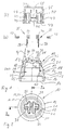
- an insulation body 10 has one lamp holder according to the invention a bottom 11 and a itself from the floor 11 extending sidewall 12, which is annular is.
- the side wall 12, which is essentially rotationally symmetrical comprises an adapter section 13 extending from the floor, an internal thread section adjoining it in the axial direction 14 and an edge section 15, which has a receiving opening 16 of one of the side wall 12 and the bottom 11 enclosed receiving space 17th circumferentially surrounds.
- the outer peripheral surface 18 of the adapter section 13 is substantially represents a conical surface, goes over a conical step 21 in a likewise conical outer peripheral surface 22 to which an outer peripheral surface 23 of the edge section 15 adjoins the has a lower taper than the outer peripheral surface 22.
- the opening angle ⁇ of the conical outer peripheral surface 22 belonging cone is between 20 ° and 25 °.
- the corresponding opening angles to the outer peripheral surfaces 18 and 23 of the adapter section 13 or the cone belonging to the edge section 15 are somewhat smaller, so that the increase in thickness of the side wall 12 is smaller in these areas than the increase in thickness in the area of the internal thread section 14. In particular, this results in a compact structure of the insulation body 10 reached with a sufficiently large wall thickness in the internal thread section 14.
- the receiving space 17 for a lamp base 24 (see Figure 4) has in the direct connection to the receiving opening 16 an entrance area 25 on which there is a threaded area 26 and subsequently a contact area 27 connect.
- two contact bushings 30 are formed, which are essentially Are L-shaped and each other with respect to a radial center line are mirror images so opposite that the short legs of the L-shape the bank feed-throughs 30 face each other.
- the Bottom 11 On its inside 36 the Bottom 11 has a central projection 37, which serves a contact tab 38 one of the contact elements 35 together with a center contact 39 of a lamp base 24, as shown in FIG is.
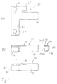
- Figure 3a shows a blank 35 'from an electrically good conductive plastically deformable, flat material, preferably from a Metal sheet, in particular made of copper or aluminum sheet.
- the Blank 35 ' has a contact tab section 38', a clamping sleeve section 34 'and a retaining tab portion 40'.
- first contact element 35 In order to create a first contact element 35, it becomes the retaining tab section 40 'adjacent portion of the ferrule portion 34 'of the blank 35' bent out of the plane of the drawing, while the free portion of the ferrule portion 34 in the 3d is bent so that the holes 41 and 42nd come to lie on top of each other.
- first contact element 35 with a receiving space for a Wire or strand end surrounding, during a ferrule 34, one Contact flag 38 and a retaining tab 40 made.
- the holding rag 40 is perpendicular to the contact lug 38 and forms an L-shape that corresponds to the L-shape of one of the contact bushings 30.
- a second Form contact element 35 that with respect to the arrangement of Clamping sleeve 34 and holding tab 40 mirror-symmetrical to the first contact element 35, the ferrule portion 34 'and the retaining tab portion 40 'of the cut 35' from the drawing plane folded down so that the contact element 35 shown in Figure 3c with contact tab 38, clamping sleeve 34 and retaining tab 40 results.
- an adapter or a holder 20 which has axially cut-out retaining tongues 45 with counter-latching elements, in particular with latching hooks 46, in a peripheral side wall 44.
- support ribs 47 are also formed on the inner circumference of the side wall 44, which lie closely on the outer circumferential surface 18 of the adapter section 13 when the insulation body 10 is inserted into the holder 20.
- a hole 48 for cable passage is formed in a bottom 49 of the bracket.
- a corresponding contact element 35 is first inserted into each of the contact bushings 30 in such a way that the clamping sleeve 34 comes to rest in the respective receiving space 33 within the U-shaped support web 32.
- the retaining tab 40 of each contact element 35 is then bent over the inside 19 of the base 11, so that each contact element 35 is held firmly in the insulation body 10.
- the bending of the retaining tab 40 is preferably carried out in the direction of the clamping sleeve 34, so that the base 11 is clamped between the retaining tab 40 and the clamping sleeve 34 for holding a contact element 35 in the insulating body 10.
- the one contact lug 38 is then bent inwards onto the central projection 37 of the base 11.
- the clamping screws 43 can be inserted into the threaded holes 41 and 42 before or after the mounting of the contact element 35 on the insulating body 10 in order to form screw terminals 34 together with the clamping sleeves.
- Lamp holder can simply be inserted into the holder 20, which is shown in Figure 4, wherein the latching hook 46 of the retaining tongues 45 snap into the recesses 19.
- Lamp holder can simply be inserted into the holder 20, which is shown in Figure 4, wherein the latching hook 46 of the retaining tongues 45 snap into the recesses 19.
- a light bulb 50 this is with a lamp base 24 in the internal thread 28 screwed so that the one contact lug 38 between the center contact 39 on the lamp base 24 and the central projection 37 of the bottom 11 is pinched.
- the other contact lug 38, the right one in FIG. 4 occurs with the external thread on the lamp base serving as external contact 24 in electrically conductive contact.
- the bracket 20 can be used as an adapter acts and which is expediently made of plastic on various Formed in such a way and provided with further functional elements his.
- the Bracket 20 is connected to a mounting bracket 51 with which the bracket 20 can be attached to a support 52 or the like.
- FIG. 6 shows another holder 20 'serving as an adapter, in which a External thread 53 on a cylinder element surrounding the holding tongues 45 54 is provided, on which a nut 55 with a clamping flange 56 can be screwed on.
- the clamping flange 56 acts with another Clamping flange 57 together, which extends from the cylinder element 54 extends outside to hold a lampshade or the like.
- the hole 48 for cable entry can not be closer to one Holding element shown are provided to the bracket 20 ' to fix a lamp stand or a lamp suspension.
- the lamp holder according to the invention can be inexpensive and simple Manufacture from porcelain with high accuracy, since it is a compact Has shape so that insulation body blanks with high pressure can be produced, which are subject to only slight shrinkage during firing are.
- the one-piece design of the contact elements leads to that this is easier and with less effort in manufacturing steps can be made and at the same time a low electrical Have resistance that is lower than conventional riveted Contact elements.
Landscapes
- Engineering & Computer Science (AREA)
- General Engineering & Computer Science (AREA)
- Fastening Of Light Sources Or Lamp Holders (AREA)
- Connecting Device With Holders (AREA)
- Vessels And Coating Films For Discharge Lamps (AREA)
- Non-Portable Lighting Devices Or Systems Thereof (AREA)
Applications Claiming Priority (2)
| Application Number | Priority Date | Filing Date | Title |
|---|---|---|---|
| DE10000245 | 2000-01-05 | ||
| DE2000100245 DE10000245B4 (de) | 2000-01-05 | 2000-01-05 | Lampenfassung |
Publications (1)
| Publication Number | Publication Date |
|---|---|
| EP1114964A2 true EP1114964A2 (fr) | 2001-07-11 |
Family
ID=7626810
Family Applications (1)
| Application Number | Title | Priority Date | Filing Date |
|---|---|---|---|
| EP01100254A Withdrawn EP1114964A2 (fr) | 2000-01-05 | 2001-01-03 | Douille de lampe |
Country Status (5)
| Country | Link |
|---|---|
| EP (1) | EP1114964A2 (fr) |
| DE (1) | DE10000245B4 (fr) |
| HR (1) | HRP20010012A2 (fr) |
| PL (1) | PL344959A1 (fr) |
| YU (1) | YU701A (fr) |
Cited By (1)
| Publication number | Priority date | Publication date | Assignee | Title |
|---|---|---|---|---|
| EP1400749A3 (fr) * | 2002-09-19 | 2007-05-30 | VERDA s.r.l. | Support pour douille de lampe, notamment pour lampes halogènes |
Family Cites Families (5)
| Publication number | Priority date | Publication date | Assignee | Title |
|---|---|---|---|---|
| DE2714922B2 (de) * | 1977-04-02 | 1979-04-19 | Broekelmann, Jaeger & Busse Gmbh & Co, 5760 Arnsberg | Elektrische Glühlampenfassung |
| DE8323973U1 (de) * | 1983-08-20 | 1983-12-15 | Brökelmann, Jaeger & Busse GmbH & Co, 5760 Arnsberg | Glühlampenfassung |
| DE9319757U1 (de) * | 1993-12-22 | 1995-04-20 | Brökelmann, Jaeger & Busse GmbH & Co, 59755 Arnsberg | Glühlampenfassung |
| DE29704696U1 (de) * | 1997-03-14 | 1997-05-15 | Hsu, Yuan-Shun, Chu-Pei, Hsing Chu | Lampenfassungsanordnung |
| DE29706338U1 (de) * | 1997-04-10 | 1997-06-26 | Brökelmann, Jaeger & Busse GmbH & Co, 59755 Arnsberg | Lampenfassung |
-
2000
- 2000-01-05 DE DE2000100245 patent/DE10000245B4/de not_active Expired - Fee Related
-
2001
- 2001-01-03 EP EP01100254A patent/EP1114964A2/fr not_active Withdrawn
- 2001-01-04 YU YU701A patent/YU701A/sh unknown
- 2001-01-04 HR HRP20010012 patent/HRP20010012A2/hr not_active Application Discontinuation
- 2001-01-05 PL PL34495901A patent/PL344959A1/xx not_active Application Discontinuation
Non-Patent Citations (1)
| Title |
|---|
| None |
Cited By (1)
| Publication number | Priority date | Publication date | Assignee | Title |
|---|---|---|---|---|
| EP1400749A3 (fr) * | 2002-09-19 | 2007-05-30 | VERDA s.r.l. | Support pour douille de lampe, notamment pour lampes halogènes |
Also Published As
| Publication number | Publication date |
|---|---|
| YU701A (sh) | 2004-03-12 |
| PL344959A1 (en) | 2001-07-16 |
| DE10000245A1 (de) | 2001-10-31 |
| DE10000245B4 (de) | 2004-02-05 |
| HRP20010012A2 (en) | 2001-12-31 |
Similar Documents
| Publication | Publication Date | Title |
|---|---|---|
| DE68908731T2 (de) | Mikrokoaxiale Verbinderfamilie. | |
| DE3587104T2 (de) | Elektrische steckervorrichtung. | |
| DE102004002404B3 (de) | Kontaktbuchse, zugehöriges Federelement und Verfahren zu deren Herstellung | |
| DE4226904C2 (de) | Crimphülse | |
| EP0291989B1 (fr) | Barre omnibus à basse tension | |
| EP3336969A1 (fr) | Dispositif de contact pour une transmission d'énergie électrique sur une carte de circuits imprimés et procédé de montage d'un tel dispositif de contacts | |
| DE4316903C2 (de) | Kontaktierungsvorrichtung für den Metallgeflechtmantel geschirmter Leitungen | |
| DE69716701T2 (de) | Luminar | |
| EP0141021A2 (fr) | Douille pour lampe à incandescence | |
| DE10000245B4 (de) | Lampenfassung | |
| EP1460734A2 (fr) | Adaptateur à un rail conducteur | |
| EP0854497A2 (fr) | Lampe compacte à décharge basse pression | |
| DE19853927A1 (de) | Anschlußdose für abgeschirmte Kabel | |
| EP0854496A2 (fr) | Lampe compacte à décharge basse pression | |
| DE102004001899A1 (de) | Sperrkreisanordnung | |
| EP0415136B1 (fr) | Insert pour connecteur à boîtier métallique | |
| EP0923105B1 (fr) | Lampe à décharge à basse pression de type compact | |
| EP0871266B1 (fr) | Douille de lampe | |
| EP0436064A1 (fr) | Douille pour lampe à incandescence | |
| EP0778640A1 (fr) | Douille de lampe, en particulier pour lampes halogènes | |
| DE4219068C2 (de) | Fassung für Leuchtstofflampen | |
| DE3817133A1 (de) | Niedervolt-stromschiene | |
| EP0415951B1 (fr) | Douille de lampe | |
| DE102021112799B4 (de) | Lampenfassung mit Halteklammer für Lampe | |
| DE102008062597B3 (de) | Verbindungselement mit mindestens einem elektrischen Steckkontakt und Verfahen zur Herstellung desselben |
Legal Events
| Date | Code | Title | Description |
|---|---|---|---|
| PUAI | Public reference made under article 153(3) epc to a published international application that has entered the european phase |
Free format text: ORIGINAL CODE: 0009012 |
|
| AK | Designated contracting states |
Kind code of ref document: A2 Designated state(s): AT BE CH CY DE DK ES FI FR GB GR IE IT LI LU MC NL PT SE TR |
|
| AX | Request for extension of the european patent |
Free format text: AL;LT;LV;MK;RO;SI |
|
| STAA | Information on the status of an ep patent application or granted ep patent |
Free format text: STATUS: THE APPLICATION IS DEEMED TO BE WITHDRAWN |
|
| 18D | Application deemed to be withdrawn |
Effective date: 20040803 |