EP1114987A2 - Diaphragme pour capteurs de pression - Google Patents
Diaphragme pour capteurs de pression Download PDFInfo
- Publication number
- EP1114987A2 EP1114987A2 EP00126274A EP00126274A EP1114987A2 EP 1114987 A2 EP1114987 A2 EP 1114987A2 EP 00126274 A EP00126274 A EP 00126274A EP 00126274 A EP00126274 A EP 00126274A EP 1114987 A2 EP1114987 A2 EP 1114987A2
- Authority
- EP
- European Patent Office
- Prior art keywords
- membrane
- trapezoidal
- membrane according
- plane
- active
- Prior art date
- Legal status (The legal status is an assumption and is not a legal conclusion. Google has not performed a legal analysis and makes no representation as to the accuracy of the status listed.)
- Granted
Links
- 239000012528 membrane Substances 0.000 claims abstract description 164
- 239000000463 material Substances 0.000 claims abstract description 11
- 230000007704 transition Effects 0.000 claims description 9
- 239000002184 metal Substances 0.000 claims description 3
- 229910052751 metal Inorganic materials 0.000 claims description 3
- 238000000034 method Methods 0.000 claims description 3
- 230000008569 process Effects 0.000 claims description 3
- 229910000831 Steel Inorganic materials 0.000 claims description 2
- 238000009530 blood pressure measurement Methods 0.000 claims description 2
- 239000010959 steel Substances 0.000 claims description 2
- VNNRSPGTAMTISX-UHFFFAOYSA-N chromium nickel Chemical compound [Cr].[Ni] VNNRSPGTAMTISX-UHFFFAOYSA-N 0.000 claims 1
- 230000009747 swallowing Effects 0.000 abstract description 2
- 210000004379 membrane Anatomy 0.000 description 117
- 238000003466 welding Methods 0.000 description 12
- 230000008901 benefit Effects 0.000 description 3
- 238000010276 construction Methods 0.000 description 3
- 230000035945 sensitivity Effects 0.000 description 3
- 230000001419 dependent effect Effects 0.000 description 2
- 238000001514 detection method Methods 0.000 description 2
- 238000009826 distribution Methods 0.000 description 2
- 239000004744 fabric Substances 0.000 description 2
- 238000005259 measurement Methods 0.000 description 2
- 238000005457 optimization Methods 0.000 description 2
- 230000015572 biosynthetic process Effects 0.000 description 1
- 238000005553 drilling Methods 0.000 description 1
- 238000004049 embossing Methods 0.000 description 1
- 230000017525 heat dissipation Effects 0.000 description 1
- 230000006872 improvement Effects 0.000 description 1
- 230000003993 interaction Effects 0.000 description 1
- 229910052759 nickel Inorganic materials 0.000 description 1
- PXHVJJICTQNCMI-UHFFFAOYSA-N nickel Substances [Ni] PXHVJJICTQNCMI-UHFFFAOYSA-N 0.000 description 1
- 229920002545 silicone oil Polymers 0.000 description 1
Images


Classifications
-
- G—PHYSICS
- G01—MEASURING; TESTING
- G01L—MEASURING FORCE, STRESS, TORQUE, WORK, MECHANICAL POWER, MECHANICAL EFFICIENCY, OR FLUID PRESSURE
- G01L19/00—Details of, or accessories for, apparatus for measuring steady or quasi-steady pressure of a fluent medium insofar as such details or accessories are not special to particular types of pressure gauges
- G01L19/04—Means for compensating for effects of changes of temperature, i.e. other than electric compensation
-
- G—PHYSICS
- G01—MEASURING; TESTING
- G01L—MEASURING FORCE, STRESS, TORQUE, WORK, MECHANICAL POWER, MECHANICAL EFFICIENCY, OR FLUID PRESSURE
- G01L19/00—Details of, or accessories for, apparatus for measuring steady or quasi-steady pressure of a fluent medium insofar as such details or accessories are not special to particular types of pressure gauges
- G01L19/0007—Fluidic connecting means
- G01L19/0046—Fluidic connecting means using isolation membranes
Definitions
- the invention relates to a membrane made of a material which is not very deformable, in particular for recording pressure, differential, absolute and / or relative pressure, with an embossed membrane structure.
- Membranes for the detection of pressure, differential, absolute and / or relative pressure have been in use for many years, usually sine, toride, saw or conical profiles can be used.
- the membrane geometries currently in use work with the same diameter and material, same Fabric thickness as well as in a same pressure and temperature range with one Linearity error of over 0.5%. Due to the linearity error, therefore Larger error tolerances in the pressure ranges provided are taken into account and can lead to considerable measurement errors. causes for the linearity error are the tangential and radial stresses that occur as well as a limited deformability of the membrane.
- Metal membranes are preferably used for low and high pressure values. so that the elasticity of the membrane is highly dependent on the chosen one Geometry is dependent and can lead to an increased linearity error.
- the invention has for its object to show a novel membrane, which is an improved temperature compensation and an essential has less linearity error.
- the solution is that the active membrane region due to the membrane surface located between the clamped edge area is determined and at least one level, centric and set off towards the center arranged measuring surface.
- the membrane surface set off towards the center contributes significantly to that the linearity error can be reduced because of an even load the membrane enters and due to the resulting harmonic Vibration behavior the inherent elasticity to reduce the linearity error contributes.
- the membrane is circular and has at least one annular trapezoidal surface.
- the at least a stepped measuring surface has at least a 45 ° bevel and / or that one or more trapezoidal membrane surfaces are formed and each have a 45 ° bevel on both sides.
- the design of a membrane according to the invention has significant advantages over this reduced linearity factor on other advantageous properties. Due to the geometry with a reduced swallowing volume, one is essential a smaller filling quantity, for example with oil, is necessary, so that a significantly reduced temperature dependency and thus improved temperature compensation is present. The reduced filling quantity results in particular due to the geometry of the membrane used, because only the area between the membrane bed and the measuring surface or the trapezoidal surfaces are needed.
- the embossed membranes are made according to their respective purpose optionally welded to one edge of the diaphragm seal, heat distortion avoided by sufficient heat dissipation becomes. As a result, there is no visible heat distortion after the welding process and an increase in linearity error is limited to less than 0.005%. For this reason, the membrane works in the intended pressure measuring range with a linearity error of ⁇ 0.04%. This low level is achieved Linearity error in that the tangential and Radial stresses as well as the tangential and radial strains mutually cancel. As a result, the linearity is largely influenced avoided and linearity errors of ⁇ 0.04% guaranteed.
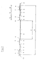
- the radially outside horizontal trapezoidal transition has the largest radius and this radius range works like an elastic joint at the edge of the membrane, so that a almost parallel sideways movement of the membrane surface and in particular the centric measuring surface to the membrane level is possible. It has also been found to be more advantageous Way shown that the inner trapezoidal transitions are the same Radii must be present in order to avoid tangential and radial stresses to compensate for the tangential and radial expansions.
- the active membrane surface can be formed lying in or parallel to the membrane plane, that the trapezoidal surface alternately below or above the membrane level are arranged horizontally or that individual trapezoidal surfaces in the membrane plane are arranged horizontally.
- the offset trapezoidal surface lying in the membrane plane Membrane surfaces are formed. Due to the different trained Trapezoidal surfaces there is the possibility of individual membrane for different Use applications and optimization of the active membrane area, as well as the linearity error.
- the parallel to or in the Trapezoidal surfaces lying at the membrane level are almost identical Spread out. Due to the large number of annular trapezoidal surfaces in the edge area the membrane and the relatively large flat measuring surface parallel vibrations are thus opposed in the center of the membrane the membrane level, which keeps the linearity error low can be.
- the active measuring surface comprises at least 20% of the active membrane diameter, while the outer edge area 2-10% of the active membrane diameter is.
- the individual ring-shaped trapezoidal surfaces point here compared to the outer edge area 1.0 - 2.5 times the width, which is has proven to be particularly advantageous.
- the edge area of the membrane has the largest possible elevation on the membrane level, so that in interaction with the larger radius selected between the first 45 ° bevel and the edge area the formation of an elastic joint is reinforced.
- the offset 45 ° trapezoidal profile ensures stability towards the center with the smaller, constant radii.
- the number of trapezoidal profiles is primarily from the membrane diameter and the thickness of the Depending on the membrane material.
- two mechanical or electronically coupled membranes are used for pressure measurement be, the trapezoidal surfaces of two membrane used symmetrical or can be arranged asymmetrically.
- the membrane here used separately as a measuring element for two pressure chambers and can be used together be coupled.
- the membrane after the embossing process of a stress-reducing treatment is subjected.
- a metal membrane according to the invention is preferred, for example Stainless chrome-nickel steel, manufactured to ensure a long service life.
- the membranes according to the invention are preferred for use with pressure transmitters or diaphragm seals.
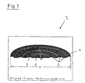
- Figure 1 shows a perspective and half-sided view of an inventive Membrane 1, which has a centrally arranged measuring surface 2 as well as several annular trapezoidal surfaces 3 and an elevated edge area 4 having.
- the number of trapezoidal surfaces 3 is the maximum Diameter of the membrane 1 and the thickness 9 of the membrane material determined.
- the width of the linear work area is based on the required Sensitivity of the measuring surface is set, setting the sensitivity by changing the outer edge elevation 10, the trapezoidal area increase 11 and the radii 6.7 and the trapezoidal surface width 12, 13.
- FIG. 3 shows the stress intensity curve over the diameter of a membrane 1, 27 according to the invention.
- FIG. 4 shows a typical characteristic curve deviation between two predefined ones Measuring range limits.
- the solid line 15 represents the linear target Work area while the thin solid line 16 as well the dashed line 17 the behavior of a real membrane 1 after Welding or before welding.
- the thermal load of the Material of the previously known membranes leads to mechanical stresses, so that between the just welded and the opposite Weld creates an antisymmetric field of tension. Immediate The consequence of this is that the membrane 1 after welding by its geometry undergoes conditional, antisymmetric deformation, causing the tangential Mobility and thus also the linear working range of the membrane 1 is restricted becomes.
- FIG. 5 shows a partially sectioned view of a diaphragm seal 20, which consists of a welded spigot 21 and a flange 22nd consists.
- Weld-on spigot 21 and flange 22 are in the exemplary embodiment shown welded together.
- the flange 22 has several circumferentially distributed Fastening holes 23, so that the diaphragm seal 20 accordingly the respective use can be installed.
- the diaphragm seal 20 can thus be flanged directly to the measuring point.
- a Membrane bed 24 formed, which has a contour adapted to the membrane 25 having. Is located between the membrane bed 24 and the membrane 25 in an intermediate space 26 an oil filling.
- the membrane 25 is normally parallel arranged to the membrane bed 24, and so that's a barely visible There is a gap to the membrane bed 24, which forms the intermediate space 26. In the event of the membrane can thus be pressurized by overpressure or underpressure Dodge on both sides. If membrane 25 comes to rest to the membrane bed 24 due to an impermissible overpressure, the membrane 25 protected from damage. Filling the intermediate space 26 takes place via a filling opening 27, which with a threaded plug, not shown can be sealed. Extends from the filling opening 27 there is an opening 28 to an axially extending connecting channel 29, which on the one hand in the intermediate space 26 and on the other hand in the pressure medium connection 30 leads to the electronic or mechanical pressure gauges can be connected.
- the circular membrane is built with its outer edge is directly welded to the membrane bed 24 without dead space, so that the intermediate space 26 is filled through the filling opening 27, for example with a silicone oil.
- the first application example the membrane 25 according to the invention as a diaphragm seal 20 in Flange construction is ideal for use in aggressive, contaminated or hot media.
- the membrane geometry is on all commercially available diaphragm seal variants, especially for tube constructions, and diaphragm seals in the food industry.
- FIG. 6 shows a pressure transmitter 50, consisting of a sensor housing 51 with a threaded shoulder 52 and one provided for screwing in Hexagon area 53.
- the sensor housing 51 is above the hexagon area 53 equipped with a hollow-walled cylindrical extension 54, which by an upper end flange 55 with attached measuring housing 56 is closed.
- Within the cylindrical extension 54 is one Membrane 57 according to the invention lying transversely to the longitudinal extent of the pressure transmitter 50 arranged.
- the membrane 57 divides the cylindrical Approach 54 into an upper 58 and lower pressure area 59, the two Pressure areas 58, 59 can be filled with different media, which are further separated from each other by the membrane 57.
- the Membrane 57 is attached to a sensor element 61 by means of a flange ring 60, which is also used to forward the recorded measured values the measuring housing 56 and the electronics located therein via supply lines 62 is connected.
- the lower pressure chamber 59 is through a bore 63 with the pressure medium to be measured, so that depending on the existing Pressure a deflection of the membrane 57 takes place, which in turn is detected by the sensor element 61.
Landscapes
- Physics & Mathematics (AREA)
- General Physics & Mathematics (AREA)
- Measuring Fluid Pressure (AREA)
Applications Claiming Priority (2)
| Application Number | Priority Date | Filing Date | Title |
|---|---|---|---|
| CH282000 | 2000-01-08 | ||
| CH20000028 | 2000-01-08 |
Publications (3)
| Publication Number | Publication Date |
|---|---|
| EP1114987A2 true EP1114987A2 (fr) | 2001-07-11 |
| EP1114987A3 EP1114987A3 (fr) | 2002-05-22 |
| EP1114987B1 EP1114987B1 (fr) | 2004-04-14 |
Family
ID=4242302
Family Applications (1)
| Application Number | Title | Priority Date | Filing Date |
|---|---|---|---|
| EP00126274A Expired - Lifetime EP1114987B1 (fr) | 2000-01-08 | 2000-12-01 | Diaphragme pour capteurs de pression |
Country Status (4)
| Country | Link |
|---|---|
| EP (1) | EP1114987B1 (fr) |
| AT (1) | ATE264500T1 (fr) |
| CH (1) | CH693469A5 (fr) |
| DE (1) | DE50006065D1 (fr) |
Cited By (9)
| Publication number | Priority date | Publication date | Assignee | Title |
|---|---|---|---|---|
| WO2003036250A1 (fr) * | 2001-10-19 | 2003-05-01 | Endress + Hauser Gmbh + Co. Kg | Systeme de transmission de pression a membrane de separation et son procede de production |
| WO2006131434A1 (fr) * | 2005-06-10 | 2006-12-14 | Endress+Hauser Gmbh+Co.Kg | Capteur de pression hydraulique |
| DE102007056844A1 (de) * | 2007-11-23 | 2009-06-10 | Endress + Hauser Gmbh + Co. Kg | Membranbett für einen Druckmittler, Druckmittler mit einem solchen Membranbett sowie Drucksensor mit einem solchen Druckmittler |
| WO2010006898A1 (fr) * | 2008-07-16 | 2010-01-21 | Endress+Hauser Gmbh+Co.Kg | Système de transmission de pression et appareil de mesure de pression équipé d’un tel système |
| WO2011061006A1 (fr) * | 2009-11-18 | 2011-05-26 | Endress+Hauser Gmbh+Co.Kg | Cellule de mesure de pression céramique capacitive |
| DE102004014919B4 (de) * | 2003-03-28 | 2013-09-26 | Denso Corporation | Drucksensor, der eine Metallmembran mit einer Konvexität besitzt |
| DE102015216626A1 (de) * | 2015-08-31 | 2017-03-02 | Siemens Aktiengesellschaft | Drucksensoranordnung sowie Messumformer zur Prozessinstrumentierung mit einer derartigen Drucksensoranordnung |
| WO2021121964A1 (fr) * | 2019-12-20 | 2021-06-24 | Endress+Hauser SE+Co. KG | Membrane de séparation, joint à membrane doté d'une membrane de séparation dudit type, et unité de mesure de pression dotée d'un joint à membrane dudit type |
| DE102020127080A1 (de) | 2020-10-14 | 2022-04-14 | Endress+Hauser SE+Co. KG | Trennmembran, Druckmittler mit einer solchen Trennmembran und Druckmessgerät mit einem solchen Druckmittler |
Families Citing this family (1)
| Publication number | Priority date | Publication date | Assignee | Title |
|---|---|---|---|---|
| DE102010042421A1 (de) | 2010-10-13 | 2012-04-19 | Endress + Hauser Gmbh + Co. Kg | Druckmittler und Druckmessaufnehmer mit einem solchen Druckmittler |
Family Cites Families (1)
| Publication number | Priority date | Publication date | Assignee | Title |
|---|---|---|---|---|
| US4241325A (en) * | 1979-03-21 | 1980-12-23 | Micro Gage, Inc. | Displacement sensing transducer |
-
2000
- 2000-01-08 CH CH00028/00A patent/CH693469A5/de not_active IP Right Cessation
- 2000-12-01 DE DE50006065T patent/DE50006065D1/de not_active Expired - Lifetime
- 2000-12-01 AT AT00126274T patent/ATE264500T1/de not_active IP Right Cessation
- 2000-12-01 EP EP00126274A patent/EP1114987B1/fr not_active Expired - Lifetime
Cited By (19)
| Publication number | Priority date | Publication date | Assignee | Title |
|---|---|---|---|---|
| WO2003036250A1 (fr) * | 2001-10-19 | 2003-05-01 | Endress + Hauser Gmbh + Co. Kg | Systeme de transmission de pression a membrane de separation et son procede de production |
| US7258059B2 (en) | 2001-10-19 | 2007-08-21 | Endress + Hauser Gmbh + Co. Kg | Pressure mediator with separating membrane and method for the production thereof |
| DE102004014919B4 (de) * | 2003-03-28 | 2013-09-26 | Denso Corporation | Drucksensor, der eine Metallmembran mit einer Konvexität besitzt |
| WO2006131434A1 (fr) * | 2005-06-10 | 2006-12-14 | Endress+Hauser Gmbh+Co.Kg | Capteur de pression hydraulique |
| US7798007B2 (en) | 2005-06-10 | 2010-09-21 | Endress + Hauser Gmbh + Co. Kg | Hydraulic pressure intermediary |
| DE102007056844A1 (de) * | 2007-11-23 | 2009-06-10 | Endress + Hauser Gmbh + Co. Kg | Membranbett für einen Druckmittler, Druckmittler mit einem solchen Membranbett sowie Drucksensor mit einem solchen Druckmittler |
| US8210048B2 (en) | 2008-07-16 | 2012-07-03 | Endress + Hauser Gmbh + Co. Kg | Pressure transfer device and pressure measuring device with such pressure transfer means |
| CN102099604A (zh) * | 2008-07-16 | 2011-06-15 | 恩德莱斯和豪瑟尔两合公司 | 压力传递装置以及具有该压力传递装置的压力测量设备 |
| RU2464467C1 (ru) * | 2008-07-16 | 2012-10-20 | Эндресс + Хаузер Гмбх + Ко.Кг | Передатчик давления и манометр |
| WO2010006898A1 (fr) * | 2008-07-16 | 2010-01-21 | Endress+Hauser Gmbh+Co.Kg | Système de transmission de pression et appareil de mesure de pression équipé d’un tel système |
| CN102099604B (zh) * | 2008-07-16 | 2013-11-20 | 恩德莱斯和豪瑟尔两合公司 | 压力传递装置以及具有该压力传递装置的压力传感器 |
| WO2011061006A1 (fr) * | 2009-11-18 | 2011-05-26 | Endress+Hauser Gmbh+Co.Kg | Cellule de mesure de pression céramique capacitive |
| DE102015216626A1 (de) * | 2015-08-31 | 2017-03-02 | Siemens Aktiengesellschaft | Drucksensoranordnung sowie Messumformer zur Prozessinstrumentierung mit einer derartigen Drucksensoranordnung |
| US10605683B2 (en) | 2015-08-31 | 2020-03-31 | Siemens Aktiengesellschaft | Pressure sensor arrangement having rotating articulation including strain gauges |
| WO2021121964A1 (fr) * | 2019-12-20 | 2021-06-24 | Endress+Hauser SE+Co. KG | Membrane de séparation, joint à membrane doté d'une membrane de séparation dudit type, et unité de mesure de pression dotée d'un joint à membrane dudit type |
| CN114787605A (zh) * | 2019-12-20 | 2022-07-22 | 恩德莱斯和豪瑟尔欧洲两合公司 | 分隔膜、具有所述类型的分隔膜的隔膜密封件以及具有所述类型的隔膜密封件的压力测量单元 |
| CN114787605B (zh) * | 2019-12-20 | 2024-07-19 | 恩德莱斯和豪瑟尔欧洲两合公司 | 分隔膜、具有所述类型的分隔膜的隔膜密封件以及具有所述类型的隔膜密封件的压力测量单元 |
| US12174079B2 (en) | 2019-12-20 | 2024-12-24 | Endress+Hauser SE+Co. KG | Separating membrane, diaphragm seal with a separating membrane of said type, and pressure measuring unit with a diaphragm seal of said type |
| DE102020127080A1 (de) | 2020-10-14 | 2022-04-14 | Endress+Hauser SE+Co. KG | Trennmembran, Druckmittler mit einer solchen Trennmembran und Druckmessgerät mit einem solchen Druckmittler |
Also Published As
| Publication number | Publication date |
|---|---|
| DE50006065D1 (de) | 2004-05-19 |
| ATE264500T1 (de) | 2004-04-15 |
| CH693469A5 (de) | 2003-08-15 |
| EP1114987B1 (fr) | 2004-04-14 |
| EP1114987A3 (fr) | 2002-05-22 |
Similar Documents
| Publication | Publication Date | Title |
|---|---|---|
| DE4234290C2 (de) | Drucksensor | |
| EP3507581B1 (fr) | Capteur de couple à rayon de dérivation | |
| EP0090872B1 (fr) | Détecteur à haute pression | |
| EP1649257B1 (fr) | Capteur de pression | |
| EP2981796B1 (fr) | Dispositif de mesure de forces | |
| DE2544505C3 (de) | Druckaufnehmer | |
| EP1114987B1 (fr) | Diaphragme pour capteurs de pression | |
| DE112011102258T5 (de) | Verbesserte Kapazitätssensoren | |
| EP0090871A1 (fr) | Détecteur à haute pression | |
| WO2015090757A1 (fr) | Capteur de pression | |
| EP3344967B1 (fr) | Ensemble capteur de pression et transducteurs de mesure pour l'instrumentation de processus à l'aide d'un tel ensemble capteur de pression | |
| DE2855746B2 (de) | Piezoelektrischer Dehnungsaufnehmer | |
| EP3126805A1 (fr) | Capteur de pression différentielle | |
| WO2012095304A1 (fr) | Dispositif destiné à convertir une force ou une pression en un signal électrique, et procédé de production d'un tel dispositif | |
| EP2729779B1 (fr) | Procédé pour relier une membrane à un boîtier de capteur | |
| EP1170578B1 (fr) | Capteur de pression résistant aux surcharges | |
| DE10245768B4 (de) | Kraftaufnehmer zum Messen von Achskräften | |
| EP2784463A1 (fr) | Cellule de mesure de pression dotée d'un dispositif d'intégration | |
| EP3641979A1 (fr) | Procédé et dispositif de mesure d'une force d'électrode d'une pince à souder | |
| CH684808A5 (de) | Drucksensor und Verfahren zu seiner Herstellung. | |
| EP3285057B1 (fr) | Capteur de pression élevée | |
| DE10162044A1 (de) | Druckmeßaufnehmer | |
| DE102005027035A1 (de) | Hydraulischer Druckmittler | |
| EP1505378A1 (fr) | Système de transmission de pression | |
| EP0629846B1 (fr) | Médiateur de pression pour tuyaux et dispositif de mesure avec un médiateur de pression pour tuyaux |
Legal Events
| Date | Code | Title | Description |
|---|---|---|---|
| PUAI | Public reference made under article 153(3) epc to a published international application that has entered the european phase |
Free format text: ORIGINAL CODE: 0009012 |
|
| AK | Designated contracting states |
Kind code of ref document: A2 Designated state(s): AT BE CH CY DE DK ES FI FR GB GR IE IT LI LU MC NL PT SE TR |
|
| AX | Request for extension of the european patent |
Free format text: AL;LT;LV;MK;RO;SI |
|
| PUAL | Search report despatched |
Free format text: ORIGINAL CODE: 0009013 |
|
| AX | Request for extension of the european patent |
Free format text: AL;LT;LV;MK;RO;SI |
|
| 17P | Request for examination filed |
Effective date: 20020426 |
|
| AKX | Designation fees paid |
Designated state(s): AT BE CH CY DE DK ES FI FR GB GR IE IT LI LU MC NL PT SE TR |
|
| GRAP | Despatch of communication of intention to grant a patent |
Free format text: ORIGINAL CODE: EPIDOSNIGR1 |
|
| GRAS | Grant fee paid |
Free format text: ORIGINAL CODE: EPIDOSNIGR3 |
|
| GRAA | (expected) grant |
Free format text: ORIGINAL CODE: 0009210 |
|
| AK | Designated contracting states |
Kind code of ref document: B1 Designated state(s): AT BE CH CY DE DK ES FI FR GB GR IE IT LI LU MC NL PT SE TR |
|
| PG25 | Lapsed in a contracting state [announced via postgrant information from national office to epo] |
Ref country code: IT Free format text: LAPSE BECAUSE OF FAILURE TO SUBMIT A TRANSLATION OF THE DESCRIPTION OR TO PAY THE FEE WITHIN THE PRESCRIBED TIME-LIMIT;WARNING: LAPSES OF ITALIAN PATENTS WITH EFFECTIVE DATE BEFORE 2007 MAY HAVE OCCURRED AT ANY TIME BEFORE 2007. THE CORRECT EFFECTIVE DATE MAY BE DIFFERENT FROM THE ONE RECORDED. Effective date: 20040414 Ref country code: FI Free format text: LAPSE BECAUSE OF FAILURE TO SUBMIT A TRANSLATION OF THE DESCRIPTION OR TO PAY THE FEE WITHIN THE PRESCRIBED TIME-LIMIT Effective date: 20040414 Ref country code: NL Free format text: LAPSE BECAUSE OF FAILURE TO SUBMIT A TRANSLATION OF THE DESCRIPTION OR TO PAY THE FEE WITHIN THE PRESCRIBED TIME-LIMIT Effective date: 20040414 Ref country code: FR Free format text: LAPSE BECAUSE OF FAILURE TO SUBMIT A TRANSLATION OF THE DESCRIPTION OR TO PAY THE FEE WITHIN THE PRESCRIBED TIME-LIMIT Effective date: 20040414 Ref country code: TR Free format text: LAPSE BECAUSE OF FAILURE TO SUBMIT A TRANSLATION OF THE DESCRIPTION OR TO PAY THE FEE WITHIN THE PRESCRIBED TIME-LIMIT Effective date: 20040414 Ref country code: CY Free format text: LAPSE BECAUSE OF FAILURE TO SUBMIT A TRANSLATION OF THE DESCRIPTION OR TO PAY THE FEE WITHIN THE PRESCRIBED TIME-LIMIT Effective date: 20040414 Ref country code: IE Free format text: LAPSE BECAUSE OF FAILURE TO SUBMIT A TRANSLATION OF THE DESCRIPTION OR TO PAY THE FEE WITHIN THE PRESCRIBED TIME-LIMIT Effective date: 20040414 Ref country code: GB Free format text: LAPSE BECAUSE OF FAILURE TO SUBMIT A TRANSLATION OF THE DESCRIPTION OR TO PAY THE FEE WITHIN THE PRESCRIBED TIME-LIMIT Effective date: 20040414 |
|
| REG | Reference to a national code |
Ref country code: GB Ref legal event code: FG4D Free format text: NOT ENGLISH |
|
| REG | Reference to a national code |
Ref country code: CH Ref legal event code: EP |
|
| REG | Reference to a national code |
Ref country code: CH Ref legal event code: NV Representative=s name: TROESCH SCHEIDEGGER WERNER AG |
|
| REF | Corresponds to: |
Ref document number: 50006065 Country of ref document: DE Date of ref document: 20040519 Kind code of ref document: P |
|
| REG | Reference to a national code |
Ref country code: IE Ref legal event code: FG4D Free format text: GERMAN |
|
| PG25 | Lapsed in a contracting state [announced via postgrant information from national office to epo] |
Ref country code: DK Free format text: LAPSE BECAUSE OF FAILURE TO SUBMIT A TRANSLATION OF THE DESCRIPTION OR TO PAY THE FEE WITHIN THE PRESCRIBED TIME-LIMIT Effective date: 20040714 Ref country code: GR Free format text: LAPSE BECAUSE OF FAILURE TO SUBMIT A TRANSLATION OF THE DESCRIPTION OR TO PAY THE FEE WITHIN THE PRESCRIBED TIME-LIMIT Effective date: 20040714 Ref country code: SE Free format text: LAPSE BECAUSE OF FAILURE TO SUBMIT A TRANSLATION OF THE DESCRIPTION OR TO PAY THE FEE WITHIN THE PRESCRIBED TIME-LIMIT Effective date: 20040714 |
|
| PG25 | Lapsed in a contracting state [announced via postgrant information from national office to epo] |
Ref country code: ES Free format text: LAPSE BECAUSE OF FAILURE TO SUBMIT A TRANSLATION OF THE DESCRIPTION OR TO PAY THE FEE WITHIN THE PRESCRIBED TIME-LIMIT Effective date: 20040725 |
|
| NLV1 | Nl: lapsed or annulled due to failure to fulfill the requirements of art. 29p and 29m of the patents act | ||
| GBV | Gb: ep patent (uk) treated as always having been void in accordance with gb section 77(7)/1977 [no translation filed] |
Effective date: 20040414 |
|
| PG25 | Lapsed in a contracting state [announced via postgrant information from national office to epo] |
Ref country code: AT Free format text: LAPSE BECAUSE OF NON-PAYMENT OF DUE FEES Effective date: 20041201 Ref country code: LU Free format text: LAPSE BECAUSE OF NON-PAYMENT OF DUE FEES Effective date: 20041201 |
|
| REG | Reference to a national code |
Ref country code: IE Ref legal event code: FD4D |
|
| PG25 | Lapsed in a contracting state [announced via postgrant information from national office to epo] |
Ref country code: BE Free format text: LAPSE BECAUSE OF NON-PAYMENT OF DUE FEES Effective date: 20041231 Ref country code: MC Free format text: LAPSE BECAUSE OF NON-PAYMENT OF DUE FEES Effective date: 20041231 |
|
| PLBE | No opposition filed within time limit |
Free format text: ORIGINAL CODE: 0009261 |
|
| STAA | Information on the status of an ep patent application or granted ep patent |
Free format text: STATUS: NO OPPOSITION FILED WITHIN TIME LIMIT |
|
| EN | Fr: translation not filed | ||
| 26N | No opposition filed |
Effective date: 20050117 |
|
| BERE | Be: lapsed |
Owner name: *ARMATURENBAU G.M.B.H. Effective date: 20041231 |
|
| BERE | Be: lapsed |
Owner name: *ARMATURENBAU G.M.B.H. Effective date: 20041231 |
|
| PG25 | Lapsed in a contracting state [announced via postgrant information from national office to epo] |
Ref country code: PT Free format text: LAPSE BECAUSE OF NON-PAYMENT OF DUE FEES Effective date: 20040914 |
|
| PGFP | Annual fee paid to national office [announced via postgrant information from national office to epo] |
Ref country code: CH Payment date: 20111222 Year of fee payment: 12 |
|
| REG | Reference to a national code |
Ref country code: CH Ref legal event code: PL |
|
| PG25 | Lapsed in a contracting state [announced via postgrant information from national office to epo] |
Ref country code: CH Free format text: LAPSE BECAUSE OF NON-PAYMENT OF DUE FEES Effective date: 20121231 Ref country code: LI Free format text: LAPSE BECAUSE OF NON-PAYMENT OF DUE FEES Effective date: 20121231 |
|
| REG | Reference to a national code |
Ref country code: DE Ref legal event code: R082 Ref document number: 50006065 Country of ref document: DE Representative=s name: DEMSKI & NOBBE PATENTANWAELTE, DE Ref country code: DE Ref legal event code: R081 Ref document number: 50006065 Country of ref document: DE Owner name: ARMANO MESSTECHNIK GMBH, DE Free format text: FORMER OWNER: ARMATURENBAU GMBH, 46487 WESEL, DE |
|
| PGFP | Annual fee paid to national office [announced via postgrant information from national office to epo] |
Ref country code: DE Payment date: 20200227 Year of fee payment: 20 |
|
| REG | Reference to a national code |
Ref country code: DE Ref legal event code: R071 Ref document number: 50006065 Country of ref document: DE |