EP1114989A2 - Dispositif pour mesurer un deséquilibre de rotor - Google Patents
Dispositif pour mesurer un deséquilibre de rotor Download PDFInfo
- Publication number
- EP1114989A2 EP1114989A2 EP00125994A EP00125994A EP1114989A2 EP 1114989 A2 EP1114989 A2 EP 1114989A2 EP 00125994 A EP00125994 A EP 00125994A EP 00125994 A EP00125994 A EP 00125994A EP 1114989 A2 EP1114989 A2 EP 1114989A2
- Authority
- EP
- European Patent Office
- Prior art keywords
- speed
- motor
- measuring
- torque
- windings
- Prior art date
- Legal status (The legal status is an assumption and is not a legal conclusion. Google has not performed a legal analysis and makes no representation as to the accuracy of the status listed.)
- Granted
Links
Images


Classifications
-
- G—PHYSICS
- G01—MEASURING; TESTING
- G01M—TESTING STATIC OR DYNAMIC BALANCE OF MACHINES OR STRUCTURES; TESTING OF STRUCTURES OR APPARATUS, NOT OTHERWISE PROVIDED FOR
- G01M1/00—Testing static or dynamic balance of machines or structures
- G01M1/14—Determining imbalance
- G01M1/16—Determining imbalance by oscillating or rotating the body to be tested
- G01M1/18—Determining imbalance by oscillating or rotating the body to be tested and running the body down from a speed greater than normal
-
- G—PHYSICS
- G01—MEASURING; TESTING
- G01M—TESTING STATIC OR DYNAMIC BALANCE OF MACHINES OR STRUCTURES; TESTING OF STRUCTURES OR APPARATUS, NOT OTHERWISE PROVIDED FOR
- G01M1/00—Testing static or dynamic balance of machines or structures
- G01M1/14—Determining imbalance
- G01M1/16—Determining imbalance by oscillating or rotating the body to be tested
- G01M1/22—Determining imbalance by oscillating or rotating the body to be tested and converting vibrations due to imbalance into electric variables
- G01M1/225—Determining imbalance by oscillating or rotating the body to be tested and converting vibrations due to imbalance into electric variables for vehicle wheels
Definitions
- the invention relates to a device according to the preamble of claim 1, as known from DE 41 24 285 A1.
- the known device has a main shaft, which is rotatably mounted in a machine housing and on which a rotor to be balanced, in particular a motor vehicle wheel can be attached.
- the main shaft is powered by a single phase AC motor driven.
- This has a single phase Main winding and one phase, especially around 90 ° electrically offset auxiliary winding.
- the one-phase AC motor especially with almost no load running Pendulum vibrations that occur are caused by an oscillating circuit reduced, in which the auxiliary winding is included.
- the drive after When the measuring speed is switched off or disconnected can the unbalance of the main shaft and / or the Clamping devices are checked or measured.
- the measurement duration and the measurement accuracy not limited.
- the object of the invention is a device of the beginning to create the type mentioned, in the pendulum vibrations, in particular in almost load-free running over a large area preselectable measuring speeds can be suppressed.
- Torque of the engine is not completely switched off, but switched to a first low torque.
- This first low torque is dimensioned so that a drop in speed, which by friction, especially in the drive or by air resistance of the rotating rotor, in particular motor vehicle wheel, is caused, is compensated. Doing so dimension the low torque so that a slight increase in speed, up to an upper speed limit.
- the torque drops to one second, slightly lower value at which the speed is reduced slowly descends, or switched off and when reached a lower speed limit becomes the first reduced torque switched on again. This allows the measuring speed can be held for any length of time.
- the speed of the main shaft can via a speed sensor designed in a known manner or incremental encoders are detected and by two-point control can set the appropriate motor current to achieve the reduced torque to maintain the measuring speed between the upper limit and the lower limit be performed.
- the motor current is set to two corresponding values, which is the delivery of the first and second reduced torque by the engine depending on the top speed Effect lower speed limit.
- the reduction in torque generated by the engine when reached the measuring speed can be done in different ways.
- an electrical resistance which in the supply winding of the main winding and auxiliary winding is switched, or by reducing the voltage in the Supply line can be reached.
- the resistance can be as Reactive resistance or ohmic resistance can be formed.
- an inductive resistor is preferably in the form a choke is used. This resistance is low Self-heating and ensures a sinusoidal current consumption, even if harmonics are superimposed on the network. With help the resistance of a relay can be bridged or the full supply voltage can be reapplied so that switched between reduced and full torque of the engine can be.
- an AC voltage regulator in particular on a semiconductor basis, which by pulse width modulation is controlled, are used. Also by switching on additional motor windings can be a reduced one Torque can be achieved.
- a four-pole can be fed from the network Single-phase AC motor, especially a capacitor motor for Be put into action.
- the torque generated by the engine is via a suitable gear, for example via a Transfer belt drive to the main shaft of the balancing machine.
- This can e.g. B. in the range of 80 to 210 rpm a preselectable measuring speed is accelerated and maintained, pendulum vibrations of the motor when the measuring speed is reached by lowering the torque and the explained Two-point control can be avoided.
- the grid frequency has practical no influence on the measuring speed.
- the electricity consumption and thus the heating of the engine is reduced because of the Motor, especially when using an inductive resistor, always a sinusoidal in the current path of the main winding Has current consumption.
- the braking of the main shaft is done by reversing the motor torque possible so that a separate service brake is not is required. This can slow down to the desired level Compensation position in one compensation plane and screwing in in the compensation position of the other compensation level be performed.
- the same windings are preferred for this purpose used for the main and auxiliary winding.
- the measurement the unbalance of the main shaft and / or the clamping device without wheel or Inertia is possible with any measurement duration.
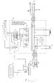
- a main shaft is shown schematically 1 a balancing machine, in particular as a wheel balancing machine is shown.
- a rotor 2 spanned, which is a motor vehicle wheel to be balanced can be.
- the main shaft drive has a single-phase AC motor 3 (Fig. 1 to 3) or 21 (Fig. 4). That from Engine 3 generated torque is via a gear 12 on the Transfer main shaft 1.
- a belt transmission preferably comes especially V-ribbed belts for use. On such a transmission enables the belt tension to be changed, which increases the friction occurring in the belt transmission or can be reduced. This allows the Rise rate of the measuring speed, especially in the two-point control influence in the range of the measuring speed.
- the single-phase AC motor 3 has more preferably Way a four-pole stator winding, which is a main winding 4 of the engine. To start the engine this a phase-shifted (in particular 90 °) auxiliary winding 5.
- the motor 3 can be from a single-phase AC network 14th operate.
- the main winding 4 and the auxiliary winding 5 are preferably the same windings, so that in both directions of rotation an approximately equal torque is generated.
- the motor can also be used to brake the Rotors 2 are used.
- Using a power switch 13 the motor 3 is connected to the network.
- the power supply takes place via an engine control device 17, which follows is explained in detail.
- the motor control device 17 has a switching device 8 with switching elements K1 to K4, which are designed as relays could be. There is also a switch actuating device 11 provided by which the various switching elements K1 up to K4 are actuated. This activity takes place depending on the speed of the main shaft 1, which is detected by a speed sensor 10 (incremental sensor).
- the Speed sensor 10 is connected to a two-point controller 9, which is connected to a microcontroller 18, in which the measured values supplied by the speed sensor 10 for a Two-point control can be evaluated.
- the switching elements K1 and K4 of the switching device 8 serve to close and open the leading to windings 4 and 5 Supply line.
- the switching element K2 can do that Motor torque can be reversed.
- a starting capacitor 16 is connected or disconnected.
- the switching element K4 can also be used depending on the switching contact position a resistor 6, which is an ohmic or reactance (Capacitance, inductance) can be in series in the too the windings 4 and 5 leading supply line switched or be separated from this ( Figure 1).
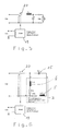
- Figure 2 can depend on the position of the switch contact of the switching element K4, the full operating voltage (position a) or a reduced operating voltage (position b) to the Main winding 4 of the motor 3 are placed.
- the reduced one Operating voltage is from a center tap of a transformer 7 taken.
- the switching elements are activated first (Relay) K1 and K3 switched on.
- the resistor 6 is thus in the Supply line of the two windings 4 and 5.
- the embodiment 2 shows the switching element K4 in the switch position b. This will reduce the supply voltage placed on windings 4 and 5. Doing so the winding 5 in both exemplary embodiments via the starting capacitor and the operating capacitor 15 out of phase powered.
- the main shaft is driven initially with reduced torque.
- the control electronics it is not known whether there is a rotor on the main shaft is open or not, the speed increases quickly. Will this be due to the signals provided by the speed sensor determined by the microcontroller 18, switching on is unnecessary full power, i.e. the closing of the switching element K4 and thus the bridging of resistor 6. In the exemplary embodiment in FIG. 1, this therefore remains Switching element K4, in the open position shown. In the embodiment of Figure 2, the switching element remains K4 in the initial switch position b.
- the switching element K4 in the embodiment 1 opened, so that the resistor 6 in the supply line the windings 4 and 5 are switched.
- the Balancing machine as high-speed runner the unbalance at high speed of> 210 RPM is also measured when the corresponding measuring speed in the exemplary embodiment in FIG. 1 the switching element K1 opened so that the resistor 6 in Supply strand of windings 4 and 5 is located.
- the unbalance measuring device acts as a high-speed motor (measuring speed at approx. 210 rpm)
- the speed limit is slightly above this value.
- the number of revolutions required to measure the unbalance in most cases before the speed limit is reached be expired, so that then explained in more detail with braking by reversing the motor torque can be started.
- the switching element K1 is opened, as in the figures 1 and 2, and the speed decreases. As soon as the Lower speed limit is reached, the switching element Kl closed again so that the limited power supply over the resistor 6 or the reduced voltage supply of the Windings 4 and 5 is started again. Because the engine provides only a reduced torque significantly reduce the resulting pendulum vibrations.
- the regulation between the upper speed limit and lower speed limit in the immediate vicinity of the respective measuring speed is from the two-point controller 9 depending on the Speed sensor 10 measured and evaluated by the microcontroller 18 Speed of the main shaft 1 regulated and the Switch actuating device 11 is controlled accordingly.
- the switch actuator 11 will be the corresponding Switching elements K1 to K4, which are preferably designed as relays are actuated or controlled.
- the switching element K1 is switched off, or opened and shortly afterwards the switching elements K2, K3 and K4 switched on.
- the full reversed torque of the Motor for braking the main shaft 1 effective. Shortly before the Standstill of the main shaft 1, all switching elements K1 to K4 switched off.
- the invention makes calmer during the unbalance measurement Main shaft 1 reached. Because the engine during the Imbalance measurement gives only a small torque, they are Pendulum vibrations in relation to the reduction in torque reduced: It can be particularly important when measuring unbalance the main shaft 1 and the clamping means, d. H. without flywheel or rotor 2, a large number of measurement cycles become. This unbalance measurement can take any measurement time be performed. Due to the two-point control, which through the interaction of the microcontroller 18 and the Two-point controller 9 in connection with the speed sensor 10 is reached, the measuring speed can be as long as required Limits are kept.
- the braking of the main shaft 1 can be done by reversing the Engine torque take place, so that a separate service brake is not needed. It can be a belt drive that has some friction generated, used. This ensures that the main shaft from a small static unbalance Movement is set.
- the friction is explained as before in the two-point speed control by the measuring speed by the overcome reduced torque delivered by the engine. Furthermore, the rate of increase in a belt transmission Measuring speed when re-driving during two-point control influenced by appropriate adjustment of the belt tension become.
- the choke has little self-heating and can therefore be housed in the electronics housing be (simple wiring).
- the throttle may reduce harmonics superimposed on the network, so that the motor 3 during measurement runs smoothly.
- Suitable chokes are in large quantities as ballasts for fluorescent lamps manufactured and are therefore inexpensive available on the market.
- FIG. 3 is another embodiment of the invention shown, in which the device for reduction of the motor current an AC voltage controller 20, in particular on a semiconductor basis, which is controlled by a controller 19 in Controlled depending on the respective speed of the rotor 2 becomes.
- the speed controller 19 is preferably a Pulse width modulator trained.
- the AC voltage regulator 20 replaces the functions of the switching element K4 and electrical resistance 6 or the transformer 7 in the Embodiments of FIGS. 1 and 2.
- the other components of the embodiment of FIG. 3 correspond to those in 1 and 2 and are for this purpose with the same reference numerals Mistake.
- the mode of operation of the AC voltage regulator is that of a step-down converter used to reduce DC voltages, as described, for example, in U. Tietze, C. Schenk “Semiconductor Circuit Technology", Springer-Verlag, 11th edition, pages 979 to 982.
- the line voltage 14 (Ue in FIGS. 5 and 6) is transformed into the output voltage Ua according to the following formula in the pulse duty factor of the pulse-width modulation PWM.
- An output voltage Ua can thus be generated Average value depending on the duty cycle between the input voltage Ue (mains voltage) and zero.
- the duty cycle of the Pulse width modulation can be changed so that between the full torque of the engine and the reduced torque can be switched when the speed is reached. How 1 and 2, the speed of the rotor 2 detected by the speed sensor 10 and over the microcontroller 18 is the evaluation of the speed of the Speed controller 19, which forms the pulse width modulator, realized.
- the control voltage Us for changing the duty cycle the pulse width modulation is dependent set by the rotor speed detected by the speed sensor 10. As in the exemplary embodiments of FIGS. 1 and 2 the measuring device can be used as a slow or fast runner operate.
- the pulse duty factor of the pulse width modulation so far changed or reduced that the engine reduced the Torque generated.
- the pulse width modulation set value of the supply current and thus measure the reduced torque delivered by the engine that the speed is slowly up to the speed limit increases and then decreased again until the speed the lower speed limit is reached. To control the speed between these two limits the duty cycle of the Pulse width modulation changed accordingly. This is the implementation of a PID controller possible.
- the circuit breaker S is a circuit breaker preferably formed on a semiconductor basis.
- the storage choke L and the consumer R are formed by the engine.
- the Operating capacitor also acts as a smoothing capacitor C.
- FIG. 6 the circuit diagram is for the consumer R. of the motor 3 with the two identical windings 4 and 5 (L1, L2).
- a single-phase AC motor used which has additional windings 22 and 23.
- the winding 22 can in series with the main winding 4 and Winding 23 can be connected in series to auxiliary winding 5 become.
- first supplied windings 4 and 5 with power As soon as the Measurement speed is reached, the additional windings 22 and 23 added to reduce the torque produce.
- the speed control in the range of the measuring speed is then carried out in the same way as in the embodiment 1, namely by switching the additional Windings 22 and 23 using the two-point control of the two-point controller 9.
Landscapes
- Physics & Mathematics (AREA)
- General Physics & Mathematics (AREA)
- Control Of Ac Motors In General (AREA)
- Testing Of Balance (AREA)
- Control Of Electric Motors In General (AREA)
- Manufacture Of Motors, Generators (AREA)
Applications Claiming Priority (2)
| Application Number | Priority Date | Filing Date | Title |
|---|---|---|---|
| DE10000235A DE10000235B4 (de) | 2000-01-05 | 2000-01-05 | Vorrichtung zum Messen einer Rotorunwucht |
| DE10000235 | 2000-01-05 |
Publications (3)
| Publication Number | Publication Date |
|---|---|
| EP1114989A2 true EP1114989A2 (fr) | 2001-07-11 |
| EP1114989A3 EP1114989A3 (fr) | 2003-04-16 |
| EP1114989B1 EP1114989B1 (fr) | 2005-01-26 |
Family
ID=7626807
Family Applications (1)
| Application Number | Title | Priority Date | Filing Date |
|---|---|---|---|
| EP00125994A Expired - Lifetime EP1114989B1 (fr) | 2000-01-05 | 2000-11-28 | Dispositif pour mesurer un deséquilibre de rotor |
Country Status (9)
| Country | Link |
|---|---|
| US (1) | US6708563B2 (fr) |
| EP (1) | EP1114989B1 (fr) |
| JP (1) | JP4521148B2 (fr) |
| KR (1) | KR100748474B1 (fr) |
| AU (1) | AU2166501A (fr) |
| DE (1) | DE10000235B4 (fr) |
| ES (1) | ES2235746T3 (fr) |
| TW (1) | TW494228B (fr) |
| WO (1) | WO2001050108A1 (fr) |
Cited By (2)
| Publication number | Priority date | Publication date | Assignee | Title |
|---|---|---|---|---|
| EP1331472A3 (fr) * | 2002-01-25 | 2004-08-18 | Snap-On Equipment GmbH | Procédé et dispositif d'équilibrage d'une roue de véhicule |
| EP1321755A3 (fr) * | 2001-12-12 | 2005-05-25 | Snap-On Equipment GmbH | Méthode et dispositif pour équilibrer une roue de véhicule en tournant la roue |
Families Citing this family (6)
| Publication number | Priority date | Publication date | Assignee | Title |
|---|---|---|---|---|
| DE10202897B4 (de) * | 2002-01-25 | 2013-04-04 | Snap-On Equipment Gmbh | Vorrichtung und Verfahren zum Messen einer Unwucht eines Motorrad-Rades |
| DE102004017767B4 (de) * | 2004-04-13 | 2013-09-19 | Snap-On Equipment Gmbh | Verfahren und Vorrichtung zum Auswuchten eines Fahrzeugrades |
| US7225673B2 (en) * | 2005-04-13 | 2007-06-05 | Alstom Technology Ltd. | Method for testing the thermally induced unbalance of a rotating machine part, in particular the rotor of a turbogenerator, and device for carrying out the method |
| EP1904975A4 (fr) * | 2005-07-12 | 2014-05-14 | Technion Res & Dev Foundation | Systeme et procede de detection active d'asymetrie dans des structures rotatives |
| US20130113457A1 (en) * | 2011-11-04 | 2013-05-09 | Kohler Co. | Method of sensing generator speed |
| JP2015116092A (ja) * | 2013-12-13 | 2015-06-22 | トヨタ自動車株式会社 | 電動車両 |
Family Cites Families (21)
| Publication number | Priority date | Publication date | Assignee | Title |
|---|---|---|---|---|
| US2161207A (en) * | 1930-05-06 | 1939-06-06 | Tremont Products Corp | Spring motor speed control |
| US2628334A (en) * | 1945-03-14 | 1953-02-10 | Vickers Inc | Compensated follow-up system |
| US3916279A (en) * | 1973-08-20 | 1975-10-28 | Hitachi Ltd | Friction compensating apparatus for load moving machines |
| JPS5812200B2 (ja) * | 1973-11-02 | 1983-03-07 | 株式会社日立製作所 | ヘイコウウンパンキノ セイギヨソウチ |
| JPS5357415A (en) * | 1976-11-02 | 1978-05-24 | Mitsubishi Electric Corp | Solid commutator motor device |
| US4215305A (en) * | 1978-10-02 | 1980-07-29 | General Electric Company | Excitation commanding for current fed motor drives |
| US4423632A (en) * | 1981-02-25 | 1984-01-03 | Qyl Inc. | Method and apparatus to determine the imbalance in a rotating object |
| US4467649A (en) * | 1982-05-25 | 1984-08-28 | American Hofmann Corporation | Apparatus for balancing rotatable bodies |
| US4501155A (en) * | 1983-06-29 | 1985-02-26 | Rheometrics, Inc. | Compensated rheometer |
| DE3422458A1 (de) * | 1984-06-16 | 1985-12-19 | Robert Bosch Gmbh, 7000 Stuttgart | Drehzahlregeleinrichtung fuer einen wechselstrommotor |
| JPS6130738A (ja) * | 1984-07-24 | 1986-02-13 | Mitsubishi Heavy Ind Ltd | 回転試験装置 |
| JPH07117472B2 (ja) * | 1988-01-22 | 1995-12-18 | 理研計器株式会社 | 動釣合試験装置における校正方法、及びその装置 |
| DE3923191C2 (de) * | 1989-07-13 | 1994-02-24 | Hofmann Werkstatt Technik | Vorrichtung zum Messen der Unwucht eines Rotors, insbesondere eines Kraftfahrzeugrades |
| US5154242A (en) * | 1990-08-28 | 1992-10-13 | Matsushita Electric Works, Ltd. | Power tools with multi-stage tightening torque control |
| DE4101341A1 (de) * | 1991-01-18 | 1992-07-23 | Ako Werke Gmbh & Co | Frequenzumrichter fuer einen asynchron-drehstrommotor |
| DE4124285C2 (de) * | 1991-07-22 | 2001-04-26 | Snap On Deutschland Holding | Vorrichtung zum Messen der Unwucht eines Rotors |
| DE4208989A1 (de) * | 1992-03-20 | 1993-09-23 | Philips Patentverwaltung | Verfahren zur detektion und kompensation einer unwucht bei einem durch einen motor angetriebenen rotor |
| DE4228143C2 (de) * | 1992-08-25 | 2002-07-11 | Snap On Deutschland Holding | Verfahren zum Antreiben eines zur Umwuchtmessung frei drehbaren, insbesondere angehobenen, an einem Kraftfahrzeug montierten Kraftfahrzeugrades und Vorrichtung zur Durchführung des Verfahrens |
| DE4432025B4 (de) * | 1994-09-08 | 2005-03-10 | Beissbarth Gmbh | Wuchtmaschine |
| DE19636268C2 (de) * | 1996-09-06 | 1998-07-16 | Hofmann Werkstatt Technik | Verfahren zum Eindrehen eines in einer Auswuchtmaschine drehgelagerten und mittels eines Antriebs antreibbaren Rotors, insbesondere Kraftfahrzeugrades, in Ausgleichspositionen zweier Ausgleichsebenen für einen dynamischen Unwuchtmassenausgleich |
| DE19718321C1 (de) * | 1997-04-30 | 1998-10-29 | Miele & Cie | Verfahren zum Auswuchten von rotierenden Körpern |
-
2000
- 2000-01-05 DE DE10000235A patent/DE10000235B4/de not_active Expired - Fee Related
- 2000-11-28 ES ES00125994T patent/ES2235746T3/es not_active Expired - Lifetime
- 2000-11-28 EP EP00125994A patent/EP1114989B1/fr not_active Expired - Lifetime
- 2000-12-15 KR KR1020027008643A patent/KR100748474B1/ko not_active Expired - Fee Related
- 2000-12-15 AU AU21665/01A patent/AU2166501A/en not_active Abandoned
- 2000-12-15 US US10/169,633 patent/US6708563B2/en not_active Expired - Lifetime
- 2000-12-15 WO PCT/EP2000/012795 patent/WO2001050108A1/fr not_active Ceased
- 2000-12-15 JP JP2001550008A patent/JP4521148B2/ja not_active Expired - Fee Related
-
2001
- 2001-01-05 TW TW090100252A patent/TW494228B/zh not_active IP Right Cessation
Cited By (2)
| Publication number | Priority date | Publication date | Assignee | Title |
|---|---|---|---|---|
| EP1321755A3 (fr) * | 2001-12-12 | 2005-05-25 | Snap-On Equipment GmbH | Méthode et dispositif pour équilibrer une roue de véhicule en tournant la roue |
| EP1331472A3 (fr) * | 2002-01-25 | 2004-08-18 | Snap-On Equipment GmbH | Procédé et dispositif d'équilibrage d'une roue de véhicule |
Also Published As
| Publication number | Publication date |
|---|---|
| KR100748474B1 (ko) | 2007-08-10 |
| EP1114989B1 (fr) | 2005-01-26 |
| JP2003519379A (ja) | 2003-06-17 |
| US20030101813A1 (en) | 2003-06-05 |
| ES2235746T3 (es) | 2005-07-16 |
| DE10000235B4 (de) | 2005-09-22 |
| JP4521148B2 (ja) | 2010-08-11 |
| EP1114989A3 (fr) | 2003-04-16 |
| WO2001050108A1 (fr) | 2001-07-12 |
| DE10000235A1 (de) | 2001-07-12 |
| TW494228B (en) | 2002-07-11 |
| KR20020071918A (ko) | 2002-09-13 |
| AU2166501A (en) | 2001-07-16 |
| US6708563B2 (en) | 2004-03-23 |
Similar Documents
| Publication | Publication Date | Title |
|---|---|---|
| EP0179356B1 (fr) | Procédé et dispositif de régulation d'une machine à champ tournant | |
| DE2730774C2 (fr) | ||
| DE69207694T2 (de) | Regelung einer geschalteten Reluktanzmaschine | |
| DE3686722T2 (de) | Buerstenfreier gleichstrommotor. | |
| DE3215596A1 (de) | Ventilaktuator | |
| DE102007001678A1 (de) | Fahrzeug-Generator-Motor-Steuervorrichtung | |
| EP1191676B1 (fr) | Procédé de détection de la vitesse de rotation d'un moteur à courant alternatif et système de commande de moteur | |
| DE2631547B2 (de) | Elektrischer Wechselstrommotor, insbesondere Induktionsmotor mit Käfigläufer | |
| DE10313927A1 (de) | Steuerverfahren für einen Motor mit geschalteter Reluktanz | |
| DE10000235B4 (de) | Vorrichtung zum Messen einer Rotorunwucht | |
| DE69730505T2 (de) | Betätigungs- und regelverfahren und vorrichtung, insbesondere für synchrone, permanentmagnet-motoren | |
| DE4130532A1 (de) | Verfahren und vorrichtung zur drehzahl- und/oder leistungsaufnahme-regulierung eines elektromotors | |
| WO2008034670A1 (fr) | Procédé de fonctionnement d'un moteur électrique à commutation électronique | |
| DE4442151A1 (de) | Schaltungsanordnung zum Steuern eines elektronisch kommutierten Motors | |
| EP0469177A1 (fr) | Procédé et dispositif pour le redémarrage d'un moteur à induction | |
| DE2732852C2 (de) | Schaltungsanordnung mit einer Drehanoden-Röntgenröhre zum Auslösen eines Schaltvorganges beim Erreichen einer vorgegebenen Drehzahl der Drehanode | |
| EP1443635B1 (fr) | Procédé de contrôle d'un angle d'allumage et moteur électrique alimenté en courant monophasé | |
| DE4404889A1 (de) | Elektrisches Antriebssystem für ein gleichstrombetriebenes Fahrzeug sowie Verfahren zum Steuern eines gleichstrombetriebenen Antriebs-Elektromotors | |
| DE4242665B4 (de) | Verfahren und Vorrichtung zum Rückschalten eines polumschaltbaren Motors | |
| DE1919716C3 (de) | Anordnung zur Regelung der Drehzahl eines Asynchron-KurzschluOläufermotors | |
| DE2150262C3 (de) | Drehzahlsteuerung oder -regelung für einen aus einem Wechselstromnetz gleichstromgespeisten, elektrischen Motor mit einem dazu in Reihe geschalteten Heizwiderstand | |
| DE2938625A1 (de) | Schaltungsanordnung zum energiesparen | |
| CH568679A5 (en) | Electromotor having revolution speed control - has electromagnetic coil pick-up with amplified feed back to motor power leads | |
| WO2012049041A1 (fr) | Dispositif d'entraînement servant à entraîner un élément d'appareil ménager, appareil ménager et procédé pour faire fonctionner un appareil ménager | |
| DE102005036802B3 (de) | Verfahren und Vorrichtung zur Steigerung der Effizienz eines Elektromotors |
Legal Events
| Date | Code | Title | Description |
|---|---|---|---|
| PUAI | Public reference made under article 153(3) epc to a published international application that has entered the european phase |
Free format text: ORIGINAL CODE: 0009012 |
|
| AK | Designated contracting states |
Kind code of ref document: A2 Designated state(s): AT BE CH CY DE DK ES FI FR GB GR IE IT LI LU MC NL PT SE TR |
|
| AX | Request for extension of the european patent |
Free format text: AL;LT;LV;MK;RO;SI |
|
| RAP1 | Party data changed (applicant data changed or rights of an application transferred) |
Owner name: SNAP-ON EQUIPMENT GMBH |
|
| PUAL | Search report despatched |
Free format text: ORIGINAL CODE: 0009013 |
|
| AK | Designated contracting states |
Designated state(s): AT BE CH CY DE DK ES FI FR GB GR IE IT LI LU MC NL PT SE TR |
|
| AX | Request for extension of the european patent |
Extension state: AL LT LV MK RO SI |
|
| RIC1 | Information provided on ipc code assigned before grant |
Ipc: 7G 01M 1/22 B Ipc: 7G 01M 1/18 A |
|
| 17P | Request for examination filed |
Effective date: 20030814 |
|
| AKX | Designation fees paid |
Designated state(s): ES FR GB IT |
|
| REG | Reference to a national code |
Ref country code: DE Ref legal event code: 8566 |
|
| GRAP | Despatch of communication of intention to grant a patent |
Free format text: ORIGINAL CODE: EPIDOSNIGR1 |
|
| GRAS | Grant fee paid |
Free format text: ORIGINAL CODE: EPIDOSNIGR3 |
|
| GRAA | (expected) grant |
Free format text: ORIGINAL CODE: 0009210 |
|
| AK | Designated contracting states |
Kind code of ref document: B1 Designated state(s): ES FR GB IT |
|
| REG | Reference to a national code |
Ref country code: GB Ref legal event code: FG4D Free format text: NOT ENGLISH |
|
| REG | Reference to a national code |
Ref country code: IE Ref legal event code: FG4D Free format text: GERMAN |
|
| GBT | Gb: translation of ep patent filed (gb section 77(6)(a)/1977) |
Effective date: 20050321 |
|
| REG | Reference to a national code |
Ref country code: ES Ref legal event code: FG2A Ref document number: 2235746 Country of ref document: ES Kind code of ref document: T3 |
|
| PLBE | No opposition filed within time limit |
Free format text: ORIGINAL CODE: 0009261 |
|
| STAA | Information on the status of an ep patent application or granted ep patent |
Free format text: STATUS: NO OPPOSITION FILED WITHIN TIME LIMIT |
|
| ET | Fr: translation filed | ||
| 26N | No opposition filed |
Effective date: 20051027 |
|
| PGFP | Annual fee paid to national office [announced via postgrant information from national office to epo] |
Ref country code: ES Payment date: 20071127 Year of fee payment: 8 |
|
| PGFP | Annual fee paid to national office [announced via postgrant information from national office to epo] |
Ref country code: GB Payment date: 20071123 Year of fee payment: 8 |
|
| GBPC | Gb: european patent ceased through non-payment of renewal fee |
Effective date: 20081128 |
|
| PG25 | Lapsed in a contracting state [announced via postgrant information from national office to epo] |
Ref country code: GB Free format text: LAPSE BECAUSE OF NON-PAYMENT OF DUE FEES Effective date: 20081128 |
|
| REG | Reference to a national code |
Ref country code: ES Ref legal event code: FD2A Effective date: 20081129 |
|
| PG25 | Lapsed in a contracting state [announced via postgrant information from national office to epo] |
Ref country code: ES Free format text: LAPSE BECAUSE OF NON-PAYMENT OF DUE FEES Effective date: 20081129 |
|
| REG | Reference to a national code |
Ref country code: FR Ref legal event code: PLFP Year of fee payment: 16 |
|
| REG | Reference to a national code |
Ref country code: FR Ref legal event code: PLFP Year of fee payment: 17 |
|
| REG | Reference to a national code |
Ref country code: FR Ref legal event code: PLFP Year of fee payment: 18 |
|
| PGFP | Annual fee paid to national office [announced via postgrant information from national office to epo] |
Ref country code: FR Payment date: 20171124 Year of fee payment: 18 |
|
| PGFP | Annual fee paid to national office [announced via postgrant information from national office to epo] |
Ref country code: IT Payment date: 20171122 Year of fee payment: 18 |
|
| PG25 | Lapsed in a contracting state [announced via postgrant information from national office to epo] |
Ref country code: FR Free format text: LAPSE BECAUSE OF NON-PAYMENT OF DUE FEES Effective date: 20181130 Ref country code: IT Free format text: LAPSE BECAUSE OF NON-PAYMENT OF DUE FEES Effective date: 20181128 |