EP1115514B1 - Dispositif pour le cintrage de toles - Google Patents
Dispositif pour le cintrage de toles Download PDFInfo
- Publication number
- EP1115514B1 EP1115514B1 EP99947370A EP99947370A EP1115514B1 EP 1115514 B1 EP1115514 B1 EP 1115514B1 EP 99947370 A EP99947370 A EP 99947370A EP 99947370 A EP99947370 A EP 99947370A EP 1115514 B1 EP1115514 B1 EP 1115514B1
- Authority
- EP
- European Patent Office
- Prior art keywords
- tool
- bending
- guide
- machine table
- eccentric
- Prior art date
- Legal status (The legal status is an assumption and is not a legal conclusion. Google has not performed a legal analysis and makes no representation as to the accuracy of the status listed.)
- Expired - Lifetime
Links
- 238000005452 bending Methods 0.000 title claims abstract description 67
- 239000002184 metal Substances 0.000 title claims abstract description 6
- 230000001154 acute effect Effects 0.000 claims description 6
- 238000000034 method Methods 0.000 description 7
- 238000012549 training Methods 0.000 description 5
- 238000013461 design Methods 0.000 description 2
- 230000005540 biological transmission Effects 0.000 description 1
- 238000011161 development Methods 0.000 description 1
- 238000006073 displacement reaction Methods 0.000 description 1
- 230000000284 resting effect Effects 0.000 description 1
- 238000013519 translation Methods 0.000 description 1
- 238000009424 underpinning Methods 0.000 description 1
Images


Classifications
-
- B—PERFORMING OPERATIONS; TRANSPORTING
- B21—MECHANICAL METAL-WORKING WITHOUT ESSENTIALLY REMOVING MATERIAL; PUNCHING METAL
- B21D—WORKING OR PROCESSING OF SHEET METAL OR METAL TUBES, RODS OR PROFILES WITHOUT ESSENTIALLY REMOVING MATERIAL; PUNCHING METAL
- B21D5/00—Bending sheet metal along straight lines, e.g. to form simple curves
- B21D5/04—Bending sheet metal along straight lines, e.g. to form simple curves on brakes making use of clamping means on one side of the work
Definitions
- the invention relates to a device for bending Sheets, the sheet being between a movable Upper cheek and a fixed machine table clamped and a leg protruding from the clamping is bent, with one below the machine table in the region of the one end of a bending beam on a movable tool table, which is rotatably supported by the movable tool table actuated, recessed bending tool.
- Such a device is from DE-A1 195 40 406 known.
- This device consists of a rotatably mounted, recessed tool which sits on a movable tool table.
- the Upper beam and the tool table are via hydraulic cylinders interconnected so that when retracting the Cylinder first drives off the top beam and the sheet stuck. Then the tool table is raised, the rotatably mounted tool with a Supports below the clamping during the press the other edge against the sheet and bend it.
- the bending tool a roller body designed for movement in the guide having.
- the latter is preferred on the one hand linearly movable in the machine table guide and on the other hand forms an axis of rotation for the bending tool. So is the entire bending path a smooth and supported rotation of the Given bending tool.
- One is preferred here Design in which the one fixed axis of rotation of the Bending tool in the tool table in an unactuated Starting position of the tool table outside a bending beam of the bending tool on which the machine table opposite side of the bending tool is arranged.
- This configuration is also according to an optimal introduction of force into the sheet to be bent given.
- an offset dimension the fixed axis of rotation of the bending tool a bending edge of the bending tool at least one Fifth of a distance between the fixed axis of rotation and a movable axis of rotation of the bending tool in leadership.
- A is preferred here Offset dimension, which is about half of the distance dimension between the fixed and the movable axis of rotation of the Bending tool corresponds.
- the movable axis of rotation is formed by the machine table in the guide supported roller body of the bending tool. It is primarily intended that the guide be horizontal, i.e. runs parallel to the machine table. Alternatively and also in combination, it can be provided that the Guidance with the machine table at an acute angle includes and / or does not run in a straight line. in this connection are also slight deviations from the horizontal conceivable, for example in the range of 1 or 2 °. However are even acute angles of more than 5 ° are conceivable. In this regard, it is suggested that the leadership go up is directed such that the roller body of the Bending tool in the course of the bending process in the guide at an acute angle towards the movable upper cheek moves.
- the leadership is first horizontal and final is directed upwards at an acute angle. Further alternatively it is proposed that the leadership is directed downwards, with the roller body in the course of the bending process - in a cross section looking at the machine table - from the movable one Upper cheek removed.
- This configuration can also alternatively to the horizontal course of the tour as can also be provided in combination with this.
- a tour also proves to be an advantage, which not straight, e.g. arched in cross section, being curved at the beginning and / or end thereof running leadership a leadership of the previous described type can connect.
- the invention further relates to a device in Speaking type, the tool table by means of Swing is articulated on the machine table.
- the wings a swing arm have an adjustable length. This change in length before and / or during the bending movement can also do the bending task be adjusted.
- the invention further relates to a device of Type described above, with advantageous further training it is proposed that the wings one Swing row opposite the swing of the others Swing row are of different lengths and / or different Have inclinations, if necessary also in the starting position.
- the wings of a lower one Swing row should be longer and made of one start different slope than the swing of an upper one Swing series.
- the invention relates to a device of described type, in which in an advantageous manner it is proposed that the position of the rocker pivot points is adjustable.
- the invention is also concerned with a device of the type described, which is advantageous in that regard Way is that the wings the swing arm rows in the unactuated starting position take different angles of attack.
- the invention relates to a device in of the type described above, with the upper cheek and the tool table via a hydraulic cylinder are interconnected.
- a hydraulic cylinder such an arrangement too is known from DE-A1 195 40 406 mentioned at the outset, where the hydraulic cylinder on the tool table fastened directly with its one free end the upper cheek acts.
- the hydraulic cylinder preferred on the top beam indirectly, for example by means of an eccentric crank rocker acts.
- the holding forces become automatic to the movement of the bending tool and this occurring forces adjusted.
- the hydraulic cylinder via the eccentric crank arm first lower the upper cheek Clamping the sheet to be bent.
- the invention also relates to a device according to the Features of the preamble of claim 1, wherein for advantageous development of this device is proposed is that the upper cheek regardless of the Tool table is adjustable.
- the upper cheek be separately linearly displaceable.
- the independently adjustable top beam can be driven in a further embodiment of the bending process, d. H. the tool table is raised automatically.
- the subject of the invention provided that the upper cheek in a machine table fixed upper cheek guide is vertically movable.
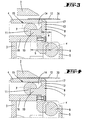
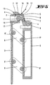
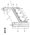
- Fig. 1 shows a device 1 for bending sheet metal, with a movable upper beam 2 and a fixed machine table 3. The latter forms on the upper cheek 2 facing upper side a fixed lower beam 4 from (see Fig. 2).
- Embodiment shown are over the length of the Device 1 four pairs of superimposed Swing 6, evenly spaced from each other, provided, the rockers 6 over the length of the Device are combined into rows of rockers.
- the tool table 5 carries a rotatably mounted one Bending tool 7.
- the latter essentially consists of one that Upper cheek 2 facing, in the unactuated starting position 2 and 3 in this embodiment aligned vertically, parallel to the tool table 5 Bending beam 8, one in the area of the lower End of the bending beam 8, on which the machine table 3 facing away from the rotating body 9 and a on the side of the bending beam facing away from this rotating body 9 8 on one aligned perpendicular to the latter Carrier 10 molded roller body 11 together.
- the Carrier 10 is based on the cross section of the bending beam 8 formed above the bisector of the same.
- the rotating body 9 forms a fixed axis of rotation x in order which the entire bending tool 7 on the tool table 5 is pivotable.
- a Recess 14 provided in which in the course of the bending process the lower beam 4 is immersed.
- the machine table 3 forms the underside of the lower beam 4 a guide 15, which in the exemplary embodiment shown straight, horizontal and on the top through the lower beam 4 and on the underside a guide base 16 fastened on the machine table side is limited.
- the vertical clear dimension of this guide 15 corresponds approximately to the diameter of the roller body 11 of the bending tool 7.
- the roller body 11 of the bending tool 7 forms in the Guide 15 a movable axis of rotation y.
- the arrangement is chosen so that an offset a fixed axis of rotation x of the bending tool 7 to an im Area of section 13 formed bending edge 17th about half of the distance dimension b between the fixed Axis of rotation x and the movable axis of rotation y in the Guide 15 corresponds.
- the guide 15 can also be provided that the latter in a cross section with the machine table 3 one includes an acute angle and thereby upwards in Direction to Oberwange 2 or down, from the Upper cheek 2 is directed away. Is further conceivable that the guide 15 curved in cross section runs.
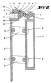
- the machine table 3 is between a left and a right machine stand 18 firmly welded.
- the upper beam 2 is open on these machine stands 18 the side facing away from the tool table 5 via bearing plates 19 hinged.
- Each machine stand 18 has a facing area on the outside further bearing plates 20 for pivoting Bracket designed as triangular bodies Eccentrics 21.
- the arrangement is chosen so that the eccentric 21 rotates in a corner area the respective bearing plate 20 with the machine table 3 connected is.
- a second, in the unactuated starting position 1 below the articulation point corner area of the eccentric lying on the machine table 3 21 rotatably carries a pair of eccentric crank rockers 22, which, overlapping the eccentric 21, up to Upper cheek 2 extends.
- this pair of eccentric crank rockers 22 on the outside on the top beam 2 in the the area facing the tool table 5 is pivoted.
- the unactuated initial position shown in Fig. 1 extends the pair of eccentric crank rockers 22 approximately vertical.
- the third via the pair of eccentric crank arms 22 protruding corner area protruding from the machine table 3 pivotally supports one end of a hydraulic cylinder 23, the other end on the underside against one tool table-side driver 24 occurs or on this is articulated.
- the unactuated starting position is limited by 3 arranged on the front of the machine table, trestles 25 underpinning the tool table 5.
- the hydraulic cylinders are used to bend a sheet 12 23 extended, which was initially about that of the eccentric 21 and the eccentric crank rocker 22 formed Lever translation a lowering of the upper beam 2 for clamping of the sheet 12 causes. After that forms the on the sheet 12 resting cheek 2 a Support for the hydraulic cylinder 23, then by further apart, an upward movement of the tool table 5 over the to swing arm pivot points 6 'swinging swing 6 takes place upwards. That mounted on the tool table 5 via the rotating body 9 Bending tool 7 pivots in the course of the upward movement of the tool table 5 in the direction of Upper cheek 2, the protruding from the relaxation Leg 30 of the sheet 12 bent around the upper cheek 2 becomes.
- the Hydraulic cylinder 23 After reaching the desired bending angle, the Hydraulic cylinder 23 retracted, due to the weight forces first the tool table 5 to lowers the starting position according to FIG. 1. hereafter is done by retracting the hydraulic cylinders 23 an upward movement of the upper cheek 2 via the eccentric crank rocker 22 to release the sheet 12.
- the swing 6 carrying the tool table 5 can be in a further embodiment, not shown, adjustable in length or length his.
- the lower wings of the tool table 5 be set longer than the upper one, the Bending tool 7 facing wings.
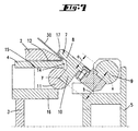
- Hydraulic cylinders 27 are rotatable on the machine table side Bearing blocks 28 held. A spread apart this hydraulic cylinder 27 causes only by the support on the bearing blocks 28 an upward movement of the tool table 5 with simultaneous pivoting movement of the bending tool 7.
- the movement of upper beam 2 and tool table 5 can be coupled. For example, after starting the Device 1 first the upper cheek 2 in the sheet 12 clamping position are shifted downwards, after which automatically the lifting movement of the tool table 5 starts.
Landscapes
- Engineering & Computer Science (AREA)
- Mechanical Engineering (AREA)
- Bending Of Plates, Rods, And Pipes (AREA)
- Folding Of Thin Sheet-Like Materials, Special Discharging Devices, And Others (AREA)
- Manufacturing Of Electric Cables (AREA)
- Shaping Of Tube Ends By Bending Or Straightening (AREA)
Claims (19)
- Dispositif (1) pour plier des tôles (12), dans lequel la tôle (12) est serrée entre une joue supérieure mobile (2) et une table de machine fixe (3) et dans lequel une branche (30) faisant saillie hors du serrage est pliée avec un outil de pliage (7) évidé et monté pivotant en-dessous de la table de machine (3) dans la zone d'extrémité d'une joue de pliage (8) sur une table d'outils mobile (5), et actionné par cette table d'outils mobile (5), caractérisé en ce que l'outil de pliage (7) est supporté, du côté de la joue de pliage (8) opposé au montage pivotant, du côté supérieur et du côté inférieur dans un guidage (15) réalisé sur la table de machine (3).
- Dispositif selon la revendication 1, caractérisé en ce que l'outil de pliage (7) comporte un corps de cylindre (11) réalisé pour se déplacer dans le guidage (15).
- Dispositif selon l'une ou plusieurs des revendications précédentes, caractérisé en ce qu'un axe de pivotement fixe (x) de l'outil de pliage (7) est disposé dans la table d'outils (5) dans une position de départ non actionnée de la table d'outils (5) à l'extérieur d'une joue de pliage (8) de l'outil de pliage (7), du côté de l'outil de pliage (7) opposé à la table de machine (3).
- Dispositif selon l'une ou plusieurs des revendications précédentes, caractérisé en ce qu'une dimension de décalage (a) de l'axe de pivotement fixe (x) de l'outil de pliage (7) par rapport à une arête de pliage (17) de l'outil de pliage (7), correspond au moins à un cinquième d'une distance (b) entre l'axe de pivotement fixe (x) et un axe de pivotement mobile (y) de l'outil de pliage (7) dans le guidage (15).
- Dispositif selon l'une ou plusieurs des revendications précédentes, caractérisé en ce que le guidage (15) s'étend horizontalement.
- Dispositif selon l'une ou plusieurs des revendications précédentes, caractérisé en ce que le guidage (15) forme en section transversale un angle aigu avec la table de machine (3).
- Dispositif selon l'une ou plusieurs des revendications précédentes, caractérisé en ce que le guidage (15) est dirigé vers le haut.
- Dispositif selon l'une ou plusieurs des revendications précédentes, caractérisé en ce que le guidage (15) est tourné vers le bas.
- Dispositif selon l'une ou plusieurs des revendications précédentes, caractérisé en ce que le guidage (15) s'étend selon une courbure en section transversale.
- Dispositif selon la revendication 1, dans lequel la table d'outils (5) est articulée par des bielles oscillantes (6) sur la table de machine (3), caractérisé en ce qu'une bielle oscillante (6) présente une longueur réglable.
- Dispositif (1) selon la revendication 10, caractérisé en ce que les bielles oscillantes (6) de la rangée de bielles oscillantes présentent des longueurs différentes.
- Dispositif (1) selon la revendication 10, caractérisé en ce que la position des points d'articulation des bielles oscillantes (6') est réglable.
- Dispositif (1) selon la revendication 10, caractérisé en ce que les bielles oscillantes (6) de la rangée de bielles oscillantes, en position de départ non actionnée, prennent des angles d'attaque différents.
- Dispositif (1) selon la revendication 10, dans lequel en outre la joue supérieure (2) et la table d'outils (5) sont reliées l'une à l'autre par l'intermédiaire d'un vérin hydrauligue (23), caractérisé en ce que le vérin hydraulique (23) agit sur la joue supérieure (2) par l'intermédiaire d'une bielle oscillante (22) excentrique.
- Dispositif selon la revendication 14, caractérisé en ce que l'excentrique (21) est monté à demeure sur la table de machine et en ce que la bielle oscillante (22) excentrique est accrochée d'une part à l'excentrique (21) et d'autre part à la joue supérieure (2).
- Dispositif selon l'une ou plusieurs des revendications 14 à 15, caractérisé en ce que l'excentrique (21) est réalisé sous la forme d'un triangle dont chacune des zones d'angles ou de coins est reliée pivotante respectivement au vérin hydraulique (23), à la bielle oscillante (22) excentrique et à la table de machine (3).
- Dispositif selon l'une ou plusieurs des revendications 14 à 16, caractérisé en ce que l'excentrique (21) est disposé en-dessous du vérin hydraulique (23).
- Dispositif (1) selon la revendication 1, caractérisé en ce que la joue supérieure (2) est réglable ïndépendamment de la table d'outils (5).
- Dispositif selon la revendication 18, caractérisé en ce que la joue supérieure (2) est mobile verticalement dans un guidage (26) de joue supérieure monté à demeure à la table de machine.
Applications Claiming Priority (3)
| Application Number | Priority Date | Filing Date | Title |
|---|---|---|---|
| DE19844244 | 1998-09-26 | ||
| DE19844244A DE19844244A1 (de) | 1998-09-26 | 1998-09-26 | Vorrichtung zum Biegen von Blechen |
| PCT/EP1999/006866 WO2000018525A2 (fr) | 1998-09-26 | 1999-09-16 | Dispositif pour le cintrage de toles |
Publications (2)
| Publication Number | Publication Date |
|---|---|
| EP1115514A2 EP1115514A2 (fr) | 2001-07-18 |
| EP1115514B1 true EP1115514B1 (fr) | 2002-12-18 |
Family
ID=7882376
Family Applications (1)
| Application Number | Title | Priority Date | Filing Date |
|---|---|---|---|
| EP99947370A Expired - Lifetime EP1115514B1 (fr) | 1998-09-26 | 1999-09-16 | Dispositif pour le cintrage de toles |
Country Status (6)
| Country | Link |
|---|---|
| EP (1) | EP1115514B1 (fr) |
| AT (1) | ATE229852T1 (fr) |
| AU (1) | AU6084599A (fr) |
| DE (2) | DE19844244A1 (fr) |
| ES (1) | ES2189488T3 (fr) |
| WO (1) | WO2000018525A2 (fr) |
Families Citing this family (4)
| Publication number | Priority date | Publication date | Assignee | Title |
|---|---|---|---|---|
| DE20004498U1 (de) * | 2000-03-14 | 2001-08-02 | KUKA Schweissanlagen GmbH, 86165 Augsburg | Bördeleinheit |
| IT1395501B1 (it) * | 2009-05-15 | 2012-09-28 | Balestrini Renzo Spa | Supporto a doppia funzione per il bloccaggio di pezzi in lavorazione |
| CN113172137B (zh) * | 2021-04-01 | 2022-10-25 | 嘉兴逸合盛制冷科技有限公司 | 一种制冷配件加工用折边装置 |
| CN114632843B (zh) * | 2022-03-11 | 2024-08-16 | 中国民航大学 | 一种开放式多功能台式弯板机 |
Family Cites Families (3)
| Publication number | Priority date | Publication date | Assignee | Title |
|---|---|---|---|---|
| US4557132A (en) * | 1984-02-03 | 1985-12-10 | Tapco Products Company, Inc. | Sheet bending brake |
| FR2597398B1 (fr) * | 1986-04-16 | 1990-12-07 | Favrin Pierre | Presse plieuse a tablier pivotant |
| DE19540406A1 (de) * | 1994-11-02 | 1996-05-09 | Werner Dr Ing Ditscher | Vorrichtung zum Biegen von Blechen und ähnlichem tafelförmigem Material |
-
1998
- 1998-09-26 DE DE19844244A patent/DE19844244A1/de not_active Withdrawn
-
1999
- 1999-09-16 AT AT99947370T patent/ATE229852T1/de not_active IP Right Cessation
- 1999-09-16 DE DE59903860T patent/DE59903860D1/de not_active Expired - Fee Related
- 1999-09-16 ES ES99947370T patent/ES2189488T3/es not_active Expired - Lifetime
- 1999-09-16 EP EP99947370A patent/EP1115514B1/fr not_active Expired - Lifetime
- 1999-09-16 AU AU60845/99A patent/AU6084599A/en not_active Abandoned
- 1999-09-16 WO PCT/EP1999/006866 patent/WO2000018525A2/fr not_active Ceased
Also Published As
| Publication number | Publication date |
|---|---|
| ES2189488T3 (es) | 2003-07-01 |
| WO2000018525A2 (fr) | 2000-04-06 |
| DE19844244A1 (de) | 2000-03-30 |
| WO2000018525A3 (fr) | 2000-08-03 |
| AU6084599A (en) | 2000-04-17 |
| EP1115514A2 (fr) | 2001-07-18 |
| DE59903860D1 (de) | 2003-01-30 |
| ATE229852T1 (de) | 2003-01-15 |
Similar Documents
| Publication | Publication Date | Title |
|---|---|---|
| DE69805631T2 (de) | Biegepresse für metallblech | |
| DE68926538T2 (de) | Faltvorrichtung | |
| DE3238809C2 (fr) | ||
| DE3709251C2 (de) | Nähautomat | |
| DE3709210C2 (fr) | ||
| DE3709232C2 (fr) | ||
| EP0136598A2 (fr) | Dispositif pour la manipulation de feuilles de tôle | |
| DE3844840C2 (de) | Verfahren zum Ausführen mehrerer aufeinanderfolgender Biegevorgänge auf einer Blechbiegemaschine | |
| DE2649471B1 (de) | Vorrichtung zum Wegfuehren und Sammeln flexibler Werkstuecke an einer Naehmaschine | |
| DE4215795C1 (de) | Biegerichtmaschine | |
| DE69107185T2 (de) | Blechbiegemaschine. | |
| DE3434470C2 (de) | Biegepresse | |
| EP0936035A2 (fr) | Méthode pour régler la position d'une lame lors du changement de lame, ainsi qu'une machine équipée de moyens pour changer de lame | |
| DE1951538A1 (de) | Karussell-Streckformmaschine mit Drehmomentausgleich | |
| EP0429004B1 (fr) | Dispositif à plier pour plaques d'impression | |
| EP0995509A1 (fr) | Plieuse | |
| EP0497780B1 (fr) | Procede de cintrage oppose d'une tole | |
| DE19844244A1 (de) | Vorrichtung zum Biegen von Blechen | |
| DE2417631C3 (de) | Vorrichtung zum Herstellen von dornartigen Vorsprängen an der Oberfläche eines Werkstücks | |
| DE10242058B4 (de) | Kniehebelspannvorrichtung | |
| DE9404308U1 (de) | Biegemaschine zum rutschlosen Biegebearbeiten von Blechtafeln | |
| DE2201791C3 (de) | Einspann- und Richtvorrichtung für aus Blechen gepreßte, vorzugsweise konische, schlitzrohrartige Masten o.dgl. bei einer Rohrschweißvorrichtung | |
| CH696158A5 (de) | Schwenkbiegemaschine. | |
| AT519644B1 (de) | Hinteranschlageinheit sowie damit ausgestattete Fertigungsanlage | |
| DE102023113071B4 (de) | Zuhaltepresse |
Legal Events
| Date | Code | Title | Description |
|---|---|---|---|
| PUAI | Public reference made under article 153(3) epc to a published international application that has entered the european phase |
Free format text: ORIGINAL CODE: 0009012 |
|
| 17P | Request for examination filed |
Effective date: 20010323 |
|
| AK | Designated contracting states |
Kind code of ref document: A2 Designated state(s): AT BE CH CY DE DK ES FI FR GB GR IE IT LI LU MC NL PT SE |
|
| GRAG | Despatch of communication of intention to grant |
Free format text: ORIGINAL CODE: EPIDOS AGRA |
|
| RIC1 | Information provided on ipc code assigned before grant |
Free format text: 7B 21D 5/04 A |
|
| 17Q | First examination report despatched |
Effective date: 20020220 |
|
| GRAG | Despatch of communication of intention to grant |
Free format text: ORIGINAL CODE: EPIDOS AGRA |
|
| GRAH | Despatch of communication of intention to grant a patent |
Free format text: ORIGINAL CODE: EPIDOS IGRA |
|
| GRAH | Despatch of communication of intention to grant a patent |
Free format text: ORIGINAL CODE: EPIDOS IGRA |
|
| GRAA | (expected) grant |
Free format text: ORIGINAL CODE: 0009210 |
|
| AK | Designated contracting states |
Kind code of ref document: B1 Designated state(s): AT BE CH CY DE DK ES FI FR GB GR IE IT LI LU MC NL PT SE |
|
| PG25 | Lapsed in a contracting state [announced via postgrant information from national office to epo] |
Ref country code: IE Free format text: LAPSE BECAUSE OF FAILURE TO SUBMIT A TRANSLATION OF THE DESCRIPTION OR TO PAY THE FEE WITHIN THE PRESCRIBED TIME-LIMIT Effective date: 20021218 Ref country code: GR Free format text: LAPSE BECAUSE OF FAILURE TO SUBMIT A TRANSLATION OF THE DESCRIPTION OR TO PAY THE FEE WITHIN THE PRESCRIBED TIME-LIMIT Effective date: 20021218 Ref country code: FR Free format text: LAPSE BECAUSE OF FAILURE TO SUBMIT A TRANSLATION OF THE DESCRIPTION OR TO PAY THE FEE WITHIN THE PRESCRIBED TIME-LIMIT Effective date: 20021218 Ref country code: FI Free format text: LAPSE BECAUSE OF FAILURE TO SUBMIT A TRANSLATION OF THE DESCRIPTION OR TO PAY THE FEE WITHIN THE PRESCRIBED TIME-LIMIT Effective date: 20021218 |
|
| REF | Corresponds to: |
Ref document number: 229852 Country of ref document: AT Date of ref document: 20030115 Kind code of ref document: T |
|
| REG | Reference to a national code |
Ref country code: GB Ref legal event code: FG4D Free format text: NOT ENGLISH |
|
| REG | Reference to a national code |
Ref country code: CH Ref legal event code: EP |
|
| REG | Reference to a national code |
Ref country code: IE Ref legal event code: FG4D Free format text: GERMAN |
|
| REF | Corresponds to: |
Ref document number: 59903860 Country of ref document: DE Date of ref document: 20030130 Kind code of ref document: P Ref document number: 59903860 Country of ref document: DE Date of ref document: 20030130 |
|
| REG | Reference to a national code |
Ref country code: CH Ref legal event code: NV Representative=s name: R. A. EGLI & CO. PATENTANWAELTE |
|
| PG25 | Lapsed in a contracting state [announced via postgrant information from national office to epo] |
Ref country code: SE Free format text: LAPSE BECAUSE OF FAILURE TO SUBMIT A TRANSLATION OF THE DESCRIPTION OR TO PAY THE FEE WITHIN THE PRESCRIBED TIME-LIMIT Effective date: 20030318 Ref country code: DK Free format text: LAPSE BECAUSE OF FAILURE TO SUBMIT A TRANSLATION OF THE DESCRIPTION OR TO PAY THE FEE WITHIN THE PRESCRIBED TIME-LIMIT Effective date: 20030318 |
|
| GBT | Gb: translation of ep patent filed (gb section 77(6)(a)/1977) |
Effective date: 20030428 |
|
| REG | Reference to a national code |
Ref country code: ES Ref legal event code: FG2A Ref document number: 2189488 Country of ref document: ES Kind code of ref document: T3 |
|
| REG | Reference to a national code |
Ref country code: IE Ref legal event code: FD4D Ref document number: 1115514E Country of ref document: IE |
|
| PG25 | Lapsed in a contracting state [announced via postgrant information from national office to epo] |
Ref country code: LU Free format text: LAPSE BECAUSE OF NON-PAYMENT OF DUE FEES Effective date: 20030916 Ref country code: CY Free format text: LAPSE BECAUSE OF FAILURE TO SUBMIT A TRANSLATION OF THE DESCRIPTION OR TO PAY THE FEE WITHIN THE PRESCRIBED TIME-LIMIT Effective date: 20030916 |
|
| PG25 | Lapsed in a contracting state [announced via postgrant information from national office to epo] |
Ref country code: MC Free format text: LAPSE BECAUSE OF NON-PAYMENT OF DUE FEES Effective date: 20030930 |
|
| PLBE | No opposition filed within time limit |
Free format text: ORIGINAL CODE: 0009261 |
|
| STAA | Information on the status of an ep patent application or granted ep patent |
Free format text: STATUS: NO OPPOSITION FILED WITHIN TIME LIMIT |
|
| EN | Fr: translation not filed | ||
| 26N | No opposition filed |
Effective date: 20030919 |
|
| PGFP | Annual fee paid to national office [announced via postgrant information from national office to epo] |
Ref country code: DE Payment date: 20040203 Year of fee payment: 5 |
|
| PGFP | Annual fee paid to national office [announced via postgrant information from national office to epo] |
Ref country code: NL Payment date: 20040204 Year of fee payment: 5 Ref country code: AT Payment date: 20040204 Year of fee payment: 5 |
|
| PGFP | Annual fee paid to national office [announced via postgrant information from national office to epo] |
Ref country code: ES Payment date: 20040205 Year of fee payment: 5 |
|
| PGFP | Annual fee paid to national office [announced via postgrant information from national office to epo] |
Ref country code: GB Payment date: 20040206 Year of fee payment: 5 Ref country code: CH Payment date: 20040206 Year of fee payment: 5 |
|
| PGFP | Annual fee paid to national office [announced via postgrant information from national office to epo] |
Ref country code: BE Payment date: 20040209 Year of fee payment: 5 |
|
| PGFP | Annual fee paid to national office [announced via postgrant information from national office to epo] |
Ref country code: PT Payment date: 20040226 Year of fee payment: 5 |
|
| PG25 | Lapsed in a contracting state [announced via postgrant information from national office to epo] |
Ref country code: GB Free format text: LAPSE BECAUSE OF NON-PAYMENT OF DUE FEES Effective date: 20040916 Ref country code: AT Free format text: LAPSE BECAUSE OF NON-PAYMENT OF DUE FEES Effective date: 20040916 |
|
| PG25 | Lapsed in a contracting state [announced via postgrant information from national office to epo] |
Ref country code: ES Free format text: LAPSE BECAUSE OF NON-PAYMENT OF DUE FEES Effective date: 20040917 |
|
| PG25 | Lapsed in a contracting state [announced via postgrant information from national office to epo] |
Ref country code: LI Free format text: LAPSE BECAUSE OF NON-PAYMENT OF DUE FEES Effective date: 20040930 Ref country code: CH Free format text: LAPSE BECAUSE OF NON-PAYMENT OF DUE FEES Effective date: 20040930 Ref country code: BE Free format text: LAPSE BECAUSE OF NON-PAYMENT OF DUE FEES Effective date: 20040930 |
|
| PG25 | Lapsed in a contracting state [announced via postgrant information from national office to epo] |
Ref country code: PT Free format text: LAPSE BECAUSE OF NON-PAYMENT OF DUE FEES Effective date: 20050316 |
|
| BERE | Be: lapsed |
Owner name: FASTI-WERK CARL AUG. *FASTENRATH G.M.B.H. & CO. K. Effective date: 20040930 |
|
| PG25 | Lapsed in a contracting state [announced via postgrant information from national office to epo] |
Ref country code: NL Free format text: LAPSE BECAUSE OF NON-PAYMENT OF DUE FEES Effective date: 20050401 Ref country code: DE Free format text: LAPSE BECAUSE OF NON-PAYMENT OF DUE FEES Effective date: 20050401 |
|
| GBPC | Gb: european patent ceased through non-payment of renewal fee |
Effective date: 20040916 |
|
| REG | Reference to a national code |
Ref country code: CH Ref legal event code: PL |
|
| REG | Reference to a national code |
Ref country code: PT Ref legal event code: MM4A Free format text: LAPSE DUE TO NON-PAYMENT OF FEES Effective date: 20050316 |
|
| NLV4 | Nl: lapsed or anulled due to non-payment of the annual fee |
Effective date: 20050401 |
|
| PG25 | Lapsed in a contracting state [announced via postgrant information from national office to epo] |
Ref country code: IT Free format text: LAPSE BECAUSE OF NON-PAYMENT OF DUE FEES Effective date: 20050916 |
|
| REG | Reference to a national code |
Ref country code: ES Ref legal event code: FD2A Effective date: 20040917 |
|
| BERE | Be: lapsed |
Owner name: FASTI-WERK CARL AUG. *FASTENRATH G.M.B.H. & CO. K. Effective date: 20040930 |