EP1115577B1 - Imprimante à jet d'encre par gouttes à la demande, méthode d'impression et méthode de fabrication - Google Patents
Imprimante à jet d'encre par gouttes à la demande, méthode d'impression et méthode de fabrication Download PDFInfo
- Publication number
- EP1115577B1 EP1115577B1 EP99949134A EP99949134A EP1115577B1 EP 1115577 B1 EP1115577 B1 EP 1115577B1 EP 99949134 A EP99949134 A EP 99949134A EP 99949134 A EP99949134 A EP 99949134A EP 1115577 B1 EP1115577 B1 EP 1115577B1
- Authority
- EP
- European Patent Office
- Prior art keywords
- nozzle
- ink
- actuating
- nozzle axis
- ink chamber
- Prior art date
- Legal status (The legal status is an assumption and is not a legal conclusion. Google has not performed a legal analysis and makes no representation as to the accuracy of the status listed.)
- Expired - Lifetime
Links
Images





Classifications
-
- B—PERFORMING OPERATIONS; TRANSPORTING
- B41—PRINTING; LINING MACHINES; TYPEWRITERS; STAMPS
- B41J—TYPEWRITERS; SELECTIVE PRINTING MECHANISMS, i.e. MECHANISMS PRINTING OTHERWISE THAN FROM A FORME; CORRECTION OF TYPOGRAPHICAL ERRORS
- B41J2/00—Typewriters or selective printing mechanisms characterised by the printing or marking process for which they are designed
- B41J2/005—Typewriters or selective printing mechanisms characterised by the printing or marking process for which they are designed characterised by bringing liquid or particles selectively into contact with a printing material
- B41J2/01—Ink jet
- B41J2/07—Ink jet characterised by jet control
- B41J2/075—Ink jet characterised by jet control for many-valued deflection
- B41J2/095—Ink jet characterised by jet control for many-valued deflection electric field-control type
-
- B—PERFORMING OPERATIONS; TRANSPORTING
- B41—PRINTING; LINING MACHINES; TYPEWRITERS; STAMPS
- B41J—TYPEWRITERS; SELECTIVE PRINTING MECHANISMS, i.e. MECHANISMS PRINTING OTHERWISE THAN FROM A FORME; CORRECTION OF TYPOGRAPHICAL ERRORS
- B41J2/00—Typewriters or selective printing mechanisms characterised by the printing or marking process for which they are designed
- B41J2/005—Typewriters or selective printing mechanisms characterised by the printing or marking process for which they are designed characterised by bringing liquid or particles selectively into contact with a printing material
- B41J2/01—Ink jet
- B41J2/135—Nozzles
- B41J2/14—Structure thereof only for on-demand ink jet heads
- B41J2/14201—Structure of print heads with piezoelectric elements
- B41J2/14209—Structure of print heads with piezoelectric elements of finger type, chamber walls consisting integrally of piezoelectric material
-
- B—PERFORMING OPERATIONS; TRANSPORTING
- B41—PRINTING; LINING MACHINES; TYPEWRITERS; STAMPS
- B41J—TYPEWRITERS; SELECTIVE PRINTING MECHANISMS, i.e. MECHANISMS PRINTING OTHERWISE THAN FROM A FORME; CORRECTION OF TYPOGRAPHICAL ERRORS
- B41J2/00—Typewriters or selective printing mechanisms characterised by the printing or marking process for which they are designed
- B41J2/005—Typewriters or selective printing mechanisms characterised by the printing or marking process for which they are designed characterised by bringing liquid or particles selectively into contact with a printing material
- B41J2/01—Ink jet
- B41J2/135—Nozzles
- B41J2/14—Structure thereof only for on-demand ink jet heads
- B41J2/14201—Structure of print heads with piezoelectric elements
- B41J2/14209—Structure of print heads with piezoelectric elements of finger type, chamber walls consisting integrally of piezoelectric material
- B41J2002/14225—Finger type piezoelectric element on only one side of the chamber
-
- B—PERFORMING OPERATIONS; TRANSPORTING
- B41—PRINTING; LINING MACHINES; TYPEWRITERS; STAMPS
- B41J—TYPEWRITERS; SELECTIVE PRINTING MECHANISMS, i.e. MECHANISMS PRINTING OTHERWISE THAN FROM A FORME; CORRECTION OF TYPOGRAPHICAL ERRORS
- B41J2/00—Typewriters or selective printing mechanisms characterised by the printing or marking process for which they are designed
- B41J2/005—Typewriters or selective printing mechanisms characterised by the printing or marking process for which they are designed characterised by bringing liquid or particles selectively into contact with a printing material
- B41J2/01—Ink jet
- B41J2/135—Nozzles
- B41J2/14—Structure thereof only for on-demand ink jet heads
- B41J2002/14459—Matrix arrangement of the pressure chambers
-
- B—PERFORMING OPERATIONS; TRANSPORTING
- B41—PRINTING; LINING MACHINES; TYPEWRITERS; STAMPS
- B41J—TYPEWRITERS; SELECTIVE PRINTING MECHANISMS, i.e. MECHANISMS PRINTING OTHERWISE THAN FROM A FORME; CORRECTION OF TYPOGRAPHICAL ERRORS
- B41J2202/00—Embodiments of or processes related to ink-jet or thermal heads
- B41J2202/01—Embodiments of or processes related to ink-jet heads
- B41J2202/18—Electrical connection established using vias
Definitions
- the ink supply means may be disposed at a plurality of locations disposed circumferentially about the ink chamber.
- the actuating structure may taper towards the nozzle axis.
- the present invention also extends to drop-on-demand ink jet printing apparatus comprising a two-dimensional array of nozzles, each having a nozzle axis, the nozzle axes being provided in parallel; a plurality of disc-shaped ink chambers each extending about a respective nozzle axis and communicating with the respective nozzle; a homogeneous piezoelectric sheet having a two dimensional array of circularly symmetric actuating structures each having a length extending in the direction of respective nozzle axes and being associated with a respective ink chamber, each circularly symmetric wall being bridged by a respective disc-shaped roof member; and electrodes on the piezoelectric sheet enabling selective actuation of each wall thereby to eject a droplet from the associated nozzle.
- the present invention also provides a method of manufacturing drop-on-demand ink jet printing apparatus, comprising the steps of forming a nozzle plate having a two dimensional array of nozzles each having a nozzle axis, the nozzle axes being in parallel; forming a homogenous piezoelectric sheet having a two dimensional array of circularly symmetric actuating structures each having a length extending in the direction of a respective nozzle axis and being associated respectively with the nozzles, each circularly symmetric wall being bridged by a respective disc-shaped roof member; applying electrodes on the piezoelectric sheet enabling selective actuation of each wall; and laminating the nozzle plate and the piezoelectric sheet; the laminated structure providing a plurality of disc-shaped ink chambers each extending about a respective nozzle axis and communicating with the respective nozzle, such that in the manufactured apparatus, actuation of a selected wall of the piezoelectric sheet effects drop ejection from the associated nozzle.
- the plurality of ink chambers may be provided by a two dimensional array of circularly symmetric recesses formed in the piezoelectric sheet, each roof member comprising at least part of the bottom wall of a respective circularly symmetric recess.
- the electrical connections to individual electrodes may be formed on an interconnection plate mounted on the piezoelectric sheet.
- the nozzle plate and the interconnection plate may be formed from piezoelectric material.
- the nozzle plate and the interconnection plate may be formed from material thermally compatible with the piezoelectric sheet.
- An array of ink channels may be formed in the piezoelectric sheet for supplying ink to the ink chambers.
- Each ink chamber may be bounded by a generally circular structure which, in the manufactured apparatus, provides a change in acoustic impedance serving to reflect acoustic waves travelling in the ink chamber radially of the respective nozzle axis.
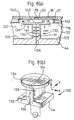
- FIG. 1(a) shows a sectional view of a single actuator 30 formed in a piezoelectric sheet 14 of a drop-on-demand ink jet printing apparatus according to a first embodiment of the present invention.
- the piezoelectric sheet 14, interposer plate 17 and nozzle plate 18 define an ink chamber 22 which extends radially about the axis of the nozzle 19 formed in the nozzle plate 18.
- the ink chamber 22 communicates with the nozzle 19 via an orifice 20 formed in the interposer plate 17.
- the piezoelectric sheet 14 forms part of a laminated structure which includes an interposer plate 17, a nozzle plate 18 and a substrate 44.
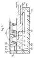
- the ink chamber 22 is supplied with ink by means of a pair of ink channels 15 formed in the piezoelectric sheet and disposed circumferentially around the ink chamber 22. As shown in Figure 1(b), the ink channels 15 are in fluid communication with manifolds 102 formed in the piezoelectric sheet 14, which in turn are supplied from an ink reservoir (not shown) via duct 36.
- Figure 1(b) is a top perspective view of a two-dimensional array of actuators, the sectional view of Figure 1(a) corresponding to a cross-section along the line A-A in Figure 1(b).
- Figure 1(b) also shows an optional dividing and support wall 101 provided to alter the ink flow characteristics.
- the wall 31 of the actuator 30 extends circumferentially around a central cavity 32, substantially co-axial with the axis of the nozzle 19, and is topped by a circular roof portion 34 which has a diameter r1.
- the roof portion is formed as a unitary piece with the walls 31 by moulding and to this end wall 31 is tapered relative to the chamber axis.
- Other machining methods such as calendering and mechanical grinding may also be suitably applicable and it is of course possible to form the roof portion 34 from a circular disc and attach it to the top of the wall 31 during assembly.
- the electrodes extend substantially over the entire top surface of the piezoelectric sheet 14 except on the very top of the roof portion 34, and over the interior surface and part of the base part 10 of the wall 31 on the underside of the piezoelectric sheet 14.
- Electrodes 24, 25 allow an electric field to be applied to the piezoelectric material of the wall 31 for both polarisation and actuation purposes. In the former case, a high value of potential difference is applied so as to align the dipoles of the piezoelectric material as indicated by arrows 30' in Figure 1(a).
- a high value of potential difference is applied so as to align the dipoles of the piezoelectric material as indicated by arrows 30' in Figure 1(a).
- Such a process is well known in the art and will not be described in greater detail here.
- the roof portion is substantially unpoled and does not contribute to droplet ejection. It would of course be possible to pole the roof portion 34, but this would complicate manufacture.
- the wall 31 Upon the application of an electric field between the electrodes 24 and 25, the wall 31 acts in so-called "direct mode" whereby it either narrows and elongates toward the nozzle 19 or thickens and contracts away from the nozzle 19 depending on the direction of the electric field in relation to the direction of poling.
- This movement generates an acoustic wave in the ink chamber 22 which travels radially within the chamber, is reflected in the ink channel 15 to converge in the centre of the ink chamber 22 to effect ejection of the ink from the nozzle 19.
- polarization electrodes 38,39 are deposited on the top and bottom surfaces of the roof portion 34 using a similar method to that described earlier and the piezoelectric sheet is polarized in the direction of the arrows 40.
- the bottom electrode 39 is then removed and a new electrode 42 applied to the bottom of the wall 31 so as to allow a polarising potential difference to be applied to wall 31 in axial direction 41.
- Both the polarization electrodes are then removed, ejection electrodes 24,25 applied over the entire top and bottom surfaces of the piezoelectric sheet 14 and the printhead assembled, as shown in Figure 2(b).
- a further interposer may be employed to support and stiffen the nozzle plate.
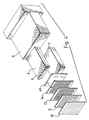
- Such a further interposer plate is shown in the third embodiment of Figure 4 which also shows a five layer laminate comprising nozzle plate 18, a first interposer layer 5, a second interposer layer 17, a piezoelectric layer 14, and an electrical connect substrate layer 44.
- the laminate is joined to an ink supply via tubes 6 formed in support plates 7 and 8. These are attached to an aluminium chassis 9.
- the nozzles formed in the nozzle plate are central with respect to the diameters of orifices in the two interposer plates and the ink chamber and are preferably spaced apart by 1/360th of an inch (0.0705mm) in the scanning direction and 17/256th of an inch (1.687mm) in the paper feed direction.
- the unequal spacings in the x and y directions reduce overload and power surges on the chips. It is of course possible to have dot spacing other than 1/360th of an inch (0.0705mm) simply by varying the distance between the centres of the ink chambers. However increasing the dot spacing by 2 means that an increased number of passes of the head are required to achieve the same dot density on the paper.
- the wall 131 is topped with a roof portion in the form of a circular disc 134.
- the disc 134 is attached to the top of the wall during assembly, and has a diameter substantially equal to or greater than the length of the wall extending in the Y axis shown in Figure 8(b), that is, in a directional substantially orthogonal to the nozzle axis.
- the disc 134 may also be formed from piezoelectric material, or from any other suitable material which is sufficiently stiff so as not to flex during movement thereof.
- ink ejected from the ink chamber 140 is replenished from the ink chamber 122 and the droplet cycle can be repeated.
- a number of pulses in quick succession can be applied to deposit a correspondingly-sized ink droplet on the substrate, as is known in the art.
- Figure 9(a) illustrates a perspective view of a fifth embodiment of a single actuator of a drop-on-demand ink jet printing apparatus.
- the fifth embodiment is similar to the fourth embodiment, with the exception that the actuating structure is replaced by a frustro-conical actuating structure 231, tapering towards the nozzle.
- the actuating structure 231 may be integral with the substrate 44, or otherwise connected thereto. Similar to the fourth embodiment, the actuating structure extends around the nozzle axis and electrodes (not shown in figure 9(a)) are provided in the cavity 232 and the external faces of the structure 231 to allow an electric field to be applied to the piezoelectric material of the structure 231 for both polarisation and actuation purposes.
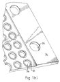
- Figure 9(b) illustrates an array of such actuators in a drop-on-demand printing apparatus, the array being similar to that shown in Figure 8(c).
Landscapes
- Particle Formation And Scattering Control In Inkjet Printers (AREA)
- Ink Jet (AREA)
Claims (20)
- Imprimante à jet d'encre par gouttes à la demande, comprenant une buse (19) sur un axe de buse ; une chambre d'encre (140) communiquant avec la buse ; une surface d'activation (134) délimitant la chambre et faisant face à la buse ; et caractérisée en ce que ladite imprimante comprend en outre une structure piézoélectrique d'activation (131), ladite structure s'étendant autour de l'axe de buse et s'étendant dans la direction de l'axe de buse ; ladite structure étant activable pour déplacer ladite surface d'activation dans la direction de l'axe de buse pour entraíner l'éjection de gouttelettes à travers la buse ; et des électrodes (125) pour appliquer un champ électrique d'activation à la structure d'activation.
- Imprimante à jet d'encre par gouttes à la demande, comprenant une buse (19) sur un axe de buse ; une chambre d'encre (22) communiquant avec la buse ; une surface d'activation (34) délimitant la chambre et faisant face à la buse ; et caractérisée en ce que ladite imprimante comprend en outre une structure piézoélectrique d'activation (31), ladite structure s'étendant dans la direction de l'axe de buse ; ladite structure étant activable pour déplacer ladite surface d'activation dans la direction de l'axe de buse pour entraíner l'éjection de gouttelettes à travers la buse ; et des électrodes pour appliquer un champ électrique d'activation à la structure d'activation, lesdites électrodes comprenant une première électrode (25) sur une face de la structure d'activation en limite de la chambre d'encre et une seconde électrode (24) sur une face opposée de la structure d'activation isolée de la chambre d'encre.
- Imprimante selon la revendication 2, dans laquelle une électrode en limite de la chambre d'encre est mise à la terre.
- Imprimante selon l'une quelconque des revendications précédentes, dans laquelle la chambre d'encre s'étend radialement autour de l'axe de buse, et la structure d'activation (31) est activable pour déplacer la surface d'activation (34) dans la direction de l'axe de buse pour entraíner, par le déplacement d'ondes acoustiques dans la chambre d'encre radialement à l'axe de buse, le dépôt de gouttelettes à travers la buse.
- Imprimante selon la revendication 4, dans laquelle la chambre d'encre s'étend sur une distance radiale R depuis l'axe de buse et la structure d'activation peut être activée pour se déplacer dans la direction de l'axe de buse dans un délai qui est au plus égal à la moitié du temps R/c, où c est la vitesse du son à travers l'encre dans la chambre d'encre.
- Imprimante selon la revendication 4 ou 5, dans laquelle la chambre d'encre est délimitée par une structure sensiblement circulaire (15) créant une variation d'impédance acoustique servant à réfléchir des ondes acoustiques circulant dans la chambre d'encre radialement à l'axe de buse.
- Imprimante selon la revendication 6, dans laquelle ladite variation d'impédance acoustique s'effectue à travers une variation de la profondeur d'encre dans la direction de l'axe de buse.
- Imprimante selon la revendication 6 ou 7, dans laquelle ladite structure circulaire définit un anneau d'encre autour de la chambre d'encre qui, dans la direction de l'axe de buse, est d'une profondeur différente de la profondeur de la chambre d'encre.
- Imprimante selon l'une quelconque des revendications précédentes, comprenant en outre des moyens d'alimentation en encre (122) en communication de fluide avec la chambre d'encre pour le réapprovisionnement de la chambre d'encre après une éjection de gouttelettes.
- Imprimante selon la revendication 9, dans laquelle les moyens d'alimentation en encre sont disposés à une pluralité d'emplacements disposés circonférentiellement autour de la chambre d'encre.
- Imprimante selon la revendication 9 ou 10, dans laquelle les moyens d'alimentation en encre servent à alimenter en encre la chambre d'encre autour de sensiblement l'ensemble de la périphérie de la chambre d'encre.
- Imprimante selon l'une quelconque des revendications précédentes, dans laquelle la structure d'activation (31) converge vers l'axe de buse.
- Imprimante selon l'une quelconque des revendications précédentes, dans laquelle la structure d'activation (31) est homogène et polarisée par rapport au champ électrique d'activation de sorte à dévier en mode direct.
- Imprimante selon la revendication 13, dans laquelle la structure d'activation est polarisée dans une direction transversale aux faces de celle-ci, le champ électrique étant appliqué selon une direction transversale aux faces de la structure d'activation.
- Imprimante selon l'une quelconque des revendications 1 à 12, dans laquelle la structure d'activation (31) est homogène et polarisée par rapport au champ électrique d'activation de façon à dévier en mode de cisaillement.
- Imprimante selon la revendication 15, dans laquelle la structure d'activation est polarisée dans des directions qui convergent vers l'axe de buse, le champ électrique étant appliqué dans une direction transversale aux faces de la structure d'activation.
- Imprimante selon la revendication 16, dans laquelle la structure d'activation (134) est constituée d'un disque en matériau piézoélectrique, le disque piézoélectrique étant polarisé dans la direction de l'axe de buse de façon à dévier en mode direct en cas d'application du champ électrique.
- Imprimante selon l'une quelconque des revendications précédentes, comprenant une pluralité desdites buses (19), chacune ayant un axe de buse respectif, lesdits axes de buse étant disposés mutuellement parallèles ; une pluralité desdites chambres d'encre (22), chacune s'étendant autour d'un axe de buse respectif ; et une feuille piézoélectrique homogène (14) portant un réseau bidimensionnel desdites structures d'activation, chaque structure d'activation étant associée à une chambre d'encre respective.
- Procédé d'impression à jet d'encre comprenant les étapes d'établissement d'une masse d'encre plane en communication avec une buse (19) comportant un axe de buse, la masse d'encre (15) s'étendant radialement à l'axe de buse, et de création dans la masse d'encre d'une frontière d'impédance s'étendant circonférentiellement à l'axe de buse ; et caractérisé en ce qu'une structure piézoélectrique d'activation (31) s'étendant dans la direction de l'axe de buse et autour de l'axe de buse est activée de manière sélective afin de déplacer une surface d'activation dans la direction de l'axe de buse de façon à engendrer une onde acoustique qui circule radialement à l'axe de buse dans la chambre d'encre et est réfléchie par la frontière d'impédance, conduisant ainsi à l'éjection d'une gouttelette d'encre à travers la buse.
- Procédé de fabrication d'une imprimante à jet d'encre par gouttes à la demande, comprenant les étapes de formation d'une plaque à buses (18) portant un réseau bidimensionnel de buses (19), chacune comportant un axe de buse, lesdits axes de buse étant mutuellement parallèles ; et caractérisé en ce que ledit procédé comprend en outre les étapes de formation d'un réseau bidimensionnel de structures d'activation (31) sur un substrat (14), chacune s'étendant dans la direction d'un axe de buse respectif et autour de l'axe de buse respectif et étant associé respectivement aux buses, une surface d'activation (34) étant prévue pour chaque structure d'activation ; d'application d'électrodes (24, 25) sur les structures d'activation permettant une activation sélective de chaque paroi ; et de stratification de la plaque à buses et du substrat ; la structure stratifiée formant une pluralité de chambres d'encre (22) en forme de disque, chacune s'étendant autour d'un axe de buse respectif et communiquant avec la buse respective, de sorte que dans l'imprimante fabriquée, l'activation d'une structure sélectionnée a pour effet d'éjecter des gouttes depuis la buse associée.
Applications Claiming Priority (3)
| Application Number | Priority Date | Filing Date | Title |
|---|---|---|---|
| GB9820755 | 1998-09-23 | ||
| GBGB9820755.8A GB9820755D0 (en) | 1998-09-23 | 1998-09-23 | Drop on demand ink jet printing apparatus |
| PCT/GB1999/003173 WO2000016981A1 (fr) | 1998-09-23 | 1999-09-23 | Imprimante a jet d'encre goutte a la demande |
Publications (2)
| Publication Number | Publication Date |
|---|---|
| EP1115577A1 EP1115577A1 (fr) | 2001-07-18 |
| EP1115577B1 true EP1115577B1 (fr) | 2005-11-23 |
Family
ID=10839356
Family Applications (1)
| Application Number | Title | Priority Date | Filing Date |
|---|---|---|---|
| EP99949134A Expired - Lifetime EP1115577B1 (fr) | 1998-09-23 | 1999-09-23 | Imprimante à jet d'encre par gouttes à la demande, méthode d'impression et méthode de fabrication |
Country Status (13)
| Country | Link |
|---|---|
| US (1) | US6331045B1 (fr) |
| EP (1) | EP1115577B1 (fr) |
| JP (1) | JP3776317B2 (fr) |
| KR (1) | KR100733983B1 (fr) |
| CN (2) | CN1298536C (fr) |
| AT (1) | ATE310641T1 (fr) |
| AU (1) | AU761033B2 (fr) |
| BR (1) | BR9913998A (fr) |
| CA (1) | CA2342367C (fr) |
| DE (1) | DE69928549T2 (fr) |
| ES (1) | ES2251227T3 (fr) |
| GB (1) | GB9820755D0 (fr) |
| WO (1) | WO2000016981A1 (fr) |
Families Citing this family (30)
| Publication number | Priority date | Publication date | Assignee | Title |
|---|---|---|---|---|
| GB0023545D0 (en) | 2000-09-26 | 2000-11-08 | Xaar Technology Ltd | Droplet deposition apparatus |
| US6428140B1 (en) * | 2001-09-28 | 2002-08-06 | Hewlett-Packard Company | Restriction within fluid cavity of fluid drop ejector |
| US6723077B2 (en) | 2001-09-28 | 2004-04-20 | Hewlett-Packard Development Company, L.P. | Cutaneous administration system |
| WO2003033951A1 (fr) * | 2001-10-13 | 2003-04-24 | Willet International Limited | Soupape electromagnetique |
| US7008048B2 (en) * | 2002-02-19 | 2006-03-07 | Brother Kogyo Kabushiki Kaisha | Ink-jet head and ink-jet printer having ink-jet head |
| US7290865B2 (en) * | 2002-02-19 | 2007-11-06 | Brother Kogyo Kabushiki Kaisha | Inkjet head |
| US7121651B2 (en) * | 2002-05-09 | 2006-10-17 | Brother Kogyo Kabushiki Kaisha | Droplet-jetting device with pressure chamber expandable by elongation of pressure-generating section |
| GB0229655D0 (en) * | 2002-12-20 | 2003-01-22 | Xaar Technology Ltd | Droplet deposition apparatus |
| US7819847B2 (en) | 2003-06-10 | 2010-10-26 | Hewlett-Packard Development Company, L.P. | System and methods for administering bioactive compositions |
| US7442180B2 (en) | 2003-06-10 | 2008-10-28 | Hewlett-Packard Development Company, L.P. | Apparatus and methods for administering bioactive compositions |
| US8128606B2 (en) | 2003-07-03 | 2012-03-06 | Hewlett-Packard Development Company, L.P. | Ophthalmic apparatus and method for administering agents to the eye |
| US8251471B2 (en) * | 2003-08-18 | 2012-08-28 | Fujifilm Dimatix, Inc. | Individual jet voltage trimming circuitry |
| US7911625B2 (en) | 2004-10-15 | 2011-03-22 | Fujifilm Dimatrix, Inc. | Printing system software architecture |
| US8085428B2 (en) | 2004-10-15 | 2011-12-27 | Fujifilm Dimatix, Inc. | Print systems and techniques |
| US8068245B2 (en) | 2004-10-15 | 2011-11-29 | Fujifilm Dimatix, Inc. | Printing device communication protocol |
| US7722147B2 (en) * | 2004-10-15 | 2010-05-25 | Fujifilm Dimatix, Inc. | Printing system architecture |
| US7907298B2 (en) | 2004-10-15 | 2011-03-15 | Fujifilm Dimatix, Inc. | Data pump for printing |
| US8199342B2 (en) | 2004-10-29 | 2012-06-12 | Fujifilm Dimatix, Inc. | Tailoring image data packets to properties of print heads |
| US7234788B2 (en) * | 2004-11-03 | 2007-06-26 | Dimatix, Inc. | Individual voltage trimming with waveforms |
| US7556327B2 (en) * | 2004-11-05 | 2009-07-07 | Fujifilm Dimatix, Inc. | Charge leakage prevention for inkjet printing |
| KR100691254B1 (ko) * | 2005-07-07 | 2007-03-12 | 성균관대학교산학협력단 | 액적공급분사장치 및 액적공급분사방법 |
| ES2423930T3 (es) | 2007-02-09 | 2013-09-25 | Advanced Liquid Logic, Inc. | Dispositivos actuadores de gotitas y métodos que emplean perlas magnéticas |
| CA2719549A1 (fr) * | 2007-04-10 | 2008-10-16 | Advanced Liquid Logic, Inc. | Dispositif de distribution de gouttelettes et procedes |
| AU2014200406B2 (en) * | 2007-04-10 | 2015-03-05 | Advanced Liquid Logic, Inc. | Droplet Dispensing Device and Methods |
| JP2012532772A (ja) * | 2009-07-10 | 2012-12-20 | フジフィルム ディマティックス, インコーポレイテッド | 高密度実装のためのmemsジェット射出構造 |
| US9278524B2 (en) | 2014-02-25 | 2016-03-08 | Funai Electric Co., Ltd. | Fluid manifold and methods of making the same |
| CN105984220B (zh) * | 2015-01-27 | 2018-07-17 | 常州市东科电子科技有限公司 | 一种多节段压电材料的3d打印机部件 |
| KR102757069B1 (ko) * | 2020-02-17 | 2025-01-20 | 삼성디스플레이 주식회사 | 잉크젯 프린팅 장치, 이를 이용한 잉크젯 헤드의 검사 방법 |
| JP7136993B1 (ja) | 2021-12-20 | 2022-09-13 | エスアイアイ・プリンテック株式会社 | ヘッドチップ、液体噴射ヘッド及び液体噴射記録装置 |
| KR20250157851A (ko) | 2024-04-29 | 2025-11-05 | 한국기계연구원 | 하이브리드 방식의 잉크젯 헤드모듈, 이를 포함하는 잉크젯 프린팅 장치 및 이의 제어방법 |
Family Cites Families (6)
| Publication number | Priority date | Publication date | Assignee | Title |
|---|---|---|---|---|
| US4233610A (en) * | 1979-06-18 | 1980-11-11 | Xerox Corporation | Hydrodynamically damped pressure pulse droplet ejector |
| US4383264A (en) * | 1980-06-18 | 1983-05-10 | Exxon Research And Engineering Co. | Demand drop forming device with interacting transducer and orifice combination |
| US5255016A (en) * | 1989-09-05 | 1993-10-19 | Seiko Epson Corporation | Ink jet printer recording head |
| US5459501A (en) * | 1993-02-01 | 1995-10-17 | At&T Global Information Solutions Company | Solid-state ink-jet print head |
| JPH08108533A (ja) * | 1994-10-06 | 1996-04-30 | Sharp Corp | インクジェットヘッド、その使用方法およびその製造方法 |
| GB9713872D0 (en) | 1997-07-02 | 1997-09-03 | Xaar Ltd | Droplet deposition apparatus |
-
1998
- 1998-09-23 GB GBGB9820755.8A patent/GB9820755D0/en not_active Ceased
-
1999
- 1999-09-23 ES ES99949134T patent/ES2251227T3/es not_active Expired - Lifetime
- 1999-09-23 CN CNB021561869A patent/CN1298536C/zh not_active Expired - Fee Related
- 1999-09-23 AT AT99949134T patent/ATE310641T1/de not_active IP Right Cessation
- 1999-09-23 WO PCT/GB1999/003173 patent/WO2000016981A1/fr not_active Ceased
- 1999-09-23 CA CA002342367A patent/CA2342367C/fr not_active Expired - Fee Related
- 1999-09-23 CN CNB998113387A patent/CN1135166C/zh not_active Expired - Fee Related
- 1999-09-23 DE DE69928549T patent/DE69928549T2/de not_active Expired - Lifetime
- 1999-09-23 JP JP2000573917A patent/JP3776317B2/ja not_active Expired - Fee Related
- 1999-09-23 EP EP99949134A patent/EP1115577B1/fr not_active Expired - Lifetime
- 1999-09-23 AU AU62123/99A patent/AU761033B2/en not_active Ceased
- 1999-09-23 KR KR1020017003530A patent/KR100733983B1/ko not_active Expired - Fee Related
- 1999-09-23 BR BRPI9913998-7A patent/BR9913998A/pt not_active IP Right Cessation
-
2001
- 2001-03-13 US US09/804,849 patent/US6331045B1/en not_active Expired - Lifetime
Also Published As
| Publication number | Publication date |
|---|---|
| JP2002526301A (ja) | 2002-08-20 |
| CN1135166C (zh) | 2004-01-21 |
| CA2342367C (fr) | 2008-04-15 |
| CN1298536C (zh) | 2007-02-07 |
| JP3776317B2 (ja) | 2006-05-17 |
| EP1115577A1 (fr) | 2001-07-18 |
| BR9913998A (pt) | 2001-07-03 |
| CA2342367A1 (fr) | 2000-03-30 |
| ATE310641T1 (de) | 2005-12-15 |
| WO2000016981A1 (fr) | 2000-03-30 |
| KR20010075213A (ko) | 2001-08-09 |
| DE69928549T2 (de) | 2006-07-13 |
| AU6212399A (en) | 2000-04-10 |
| DE69928549D1 (de) | 2005-12-29 |
| KR100733983B1 (ko) | 2007-06-29 |
| GB9820755D0 (en) | 1998-11-18 |
| AU761033B2 (en) | 2003-05-29 |
| US6331045B1 (en) | 2001-12-18 |
| CN1320079A (zh) | 2001-10-31 |
| ES2251227T3 (es) | 2006-04-16 |
| CN1480328A (zh) | 2004-03-10 |
Similar Documents
| Publication | Publication Date | Title |
|---|---|---|
| EP1115577B1 (fr) | Imprimante à jet d'encre par gouttes à la demande, méthode d'impression et méthode de fabrication | |
| AU739819B2 (en) | Drop on demand ink jet printing apparatus | |
| US5818482A (en) | Ink jet printing head | |
| JP5274741B2 (ja) | 液滴付着装置 | |
| US6582066B1 (en) | Droplet deposition apparatus and methods of manufacture thereof | |
| US6014153A (en) | Pulsed droplet deposition apparatus | |
| JPH09300609A (ja) | インクジェットヘッド | |
| US7815293B2 (en) | Ink-jet head and method of producing the same | |
| EP3981602A1 (fr) | Appareil et méthode d'impression | |
| JPWO1995010416A1 (ja) | インクジェットヘッドとその製造方法及びその駆動方法 |
Legal Events
| Date | Code | Title | Description |
|---|---|---|---|
| PUAI | Public reference made under article 153(3) epc to a published international application that has entered the european phase |
Free format text: ORIGINAL CODE: 0009012 |
|
| 17P | Request for examination filed |
Effective date: 20010412 |
|
| AK | Designated contracting states |
Kind code of ref document: A1 Designated state(s): AT BE CH CY DE DK ES FI FR GB GR IE IT LI LU MC NL PT SE |
|
| AX | Request for extension of the european patent |
Free format text: AL;LT;LV;MK;RO;SI |
|
| 17Q | First examination report despatched |
Effective date: 20030404 |
|
| GRAP | Despatch of communication of intention to grant a patent |
Free format text: ORIGINAL CODE: EPIDOSNIGR1 |
|
| RTI1 | Title (correction) |
Free format text: DROP ON DEMAND INK JET PRINTING APPARATUS, PRINTING METHOD AND MANUFACTURING METHOD |
|
| RAP1 | Party data changed (applicant data changed or rights of an application transferred) |
Owner name: XAAR TECHNOLOGY LIMITED |
|
| GRAS | Grant fee paid |
Free format text: ORIGINAL CODE: EPIDOSNIGR3 |
|
| GRAA | (expected) grant |
Free format text: ORIGINAL CODE: 0009210 |
|
| AK | Designated contracting states |
Kind code of ref document: B1 Designated state(s): AT BE CH CY DE DK ES FI FR GB GR IE IT LI LU MC NL PT SE |
|
| PG25 | Lapsed in a contracting state [announced via postgrant information from national office to epo] |
Ref country code: LI Free format text: LAPSE BECAUSE OF FAILURE TO SUBMIT A TRANSLATION OF THE DESCRIPTION OR TO PAY THE FEE WITHIN THE PRESCRIBED TIME-LIMIT Effective date: 20051123 Ref country code: FI Free format text: LAPSE BECAUSE OF FAILURE TO SUBMIT A TRANSLATION OF THE DESCRIPTION OR TO PAY THE FEE WITHIN THE PRESCRIBED TIME-LIMIT Effective date: 20051123 Ref country code: CH Free format text: LAPSE BECAUSE OF FAILURE TO SUBMIT A TRANSLATION OF THE DESCRIPTION OR TO PAY THE FEE WITHIN THE PRESCRIBED TIME-LIMIT Effective date: 20051123 Ref country code: BE Free format text: LAPSE BECAUSE OF FAILURE TO SUBMIT A TRANSLATION OF THE DESCRIPTION OR TO PAY THE FEE WITHIN THE PRESCRIBED TIME-LIMIT Effective date: 20051123 Ref country code: AT Free format text: LAPSE BECAUSE OF FAILURE TO SUBMIT A TRANSLATION OF THE DESCRIPTION OR TO PAY THE FEE WITHIN THE PRESCRIBED TIME-LIMIT Effective date: 20051123 |
|
| REG | Reference to a national code |
Ref country code: GB Ref legal event code: FG4D |
|
| REG | Reference to a national code |
Ref country code: CH Ref legal event code: EP |
|
| REF | Corresponds to: |
Ref document number: 69928549 Country of ref document: DE Date of ref document: 20051229 Kind code of ref document: P |
|
| REG | Reference to a national code |
Ref country code: IE Ref legal event code: FG4D |
|
| PG25 | Lapsed in a contracting state [announced via postgrant information from national office to epo] |
Ref country code: SE Free format text: LAPSE BECAUSE OF FAILURE TO SUBMIT A TRANSLATION OF THE DESCRIPTION OR TO PAY THE FEE WITHIN THE PRESCRIBED TIME-LIMIT Effective date: 20060223 Ref country code: GR Free format text: LAPSE BECAUSE OF FAILURE TO SUBMIT A TRANSLATION OF THE DESCRIPTION OR TO PAY THE FEE WITHIN THE PRESCRIBED TIME-LIMIT Effective date: 20060223 Ref country code: DK Free format text: LAPSE BECAUSE OF FAILURE TO SUBMIT A TRANSLATION OF THE DESCRIPTION OR TO PAY THE FEE WITHIN THE PRESCRIBED TIME-LIMIT Effective date: 20060223 |
|
| REG | Reference to a national code |
Ref country code: ES Ref legal event code: FG2A Ref document number: 2251227 Country of ref document: ES Kind code of ref document: T3 |
|
| PG25 | Lapsed in a contracting state [announced via postgrant information from national office to epo] |
Ref country code: PT Free format text: LAPSE BECAUSE OF FAILURE TO SUBMIT A TRANSLATION OF THE DESCRIPTION OR TO PAY THE FEE WITHIN THE PRESCRIBED TIME-LIMIT Effective date: 20060424 |
|
| REG | Reference to a national code |
Ref country code: CH Ref legal event code: PL |
|
| ET | Fr: translation filed | ||
| PG25 | Lapsed in a contracting state [announced via postgrant information from national office to epo] |
Ref country code: IE Free format text: LAPSE BECAUSE OF NON-PAYMENT OF DUE FEES Effective date: 20060925 |
|
| PLBE | No opposition filed within time limit |
Free format text: ORIGINAL CODE: 0009261 |
|
| STAA | Information on the status of an ep patent application or granted ep patent |
Free format text: STATUS: NO OPPOSITION FILED WITHIN TIME LIMIT |
|
| PG25 | Lapsed in a contracting state [announced via postgrant information from national office to epo] |
Ref country code: MC Free format text: LAPSE BECAUSE OF NON-PAYMENT OF DUE FEES Effective date: 20060930 |
|
| 26N | No opposition filed |
Effective date: 20060824 |
|
| REG | Reference to a national code |
Ref country code: IE Ref legal event code: MM4A |
|
| PG25 | Lapsed in a contracting state [announced via postgrant information from national office to epo] |
Ref country code: LU Free format text: LAPSE BECAUSE OF NON-PAYMENT OF DUE FEES Effective date: 20060923 |
|
| PG25 | Lapsed in a contracting state [announced via postgrant information from national office to epo] |
Ref country code: CY Free format text: LAPSE BECAUSE OF FAILURE TO SUBMIT A TRANSLATION OF THE DESCRIPTION OR TO PAY THE FEE WITHIN THE PRESCRIBED TIME-LIMIT Effective date: 20051123 |
|
| PGFP | Annual fee paid to national office [announced via postgrant information from national office to epo] |
Ref country code: NL Payment date: 20080903 Year of fee payment: 10 |
|
| PGFP | Annual fee paid to national office [announced via postgrant information from national office to epo] |
Ref country code: ES Payment date: 20081021 Year of fee payment: 10 |
|
| PGFP | Annual fee paid to national office [announced via postgrant information from national office to epo] |
Ref country code: IT Payment date: 20080927 Year of fee payment: 10 |
|
| REG | Reference to a national code |
Ref country code: NL Ref legal event code: V1 Effective date: 20100401 |
|
| PG25 | Lapsed in a contracting state [announced via postgrant information from national office to epo] |
Ref country code: NL Free format text: LAPSE BECAUSE OF NON-PAYMENT OF DUE FEES Effective date: 20100401 |
|
| PG25 | Lapsed in a contracting state [announced via postgrant information from national office to epo] |
Ref country code: IT Free format text: LAPSE BECAUSE OF NON-PAYMENT OF DUE FEES Effective date: 20090923 |
|
| REG | Reference to a national code |
Ref country code: ES Ref legal event code: FD2A Effective date: 20110714 |
|
| PG25 | Lapsed in a contracting state [announced via postgrant information from national office to epo] |
Ref country code: ES Free format text: LAPSE BECAUSE OF NON-PAYMENT OF DUE FEES Effective date: 20110704 |
|
| PG25 | Lapsed in a contracting state [announced via postgrant information from national office to epo] |
Ref country code: ES Free format text: LAPSE BECAUSE OF NON-PAYMENT OF DUE FEES Effective date: 20090924 |
|
| PGFP | Annual fee paid to national office [announced via postgrant information from national office to epo] |
Ref country code: GB Payment date: 20120919 Year of fee payment: 14 |
|
| PGFP | Annual fee paid to national office [announced via postgrant information from national office to epo] |
Ref country code: DE Payment date: 20120919 Year of fee payment: 14 Ref country code: FR Payment date: 20120926 Year of fee payment: 14 |
|
| GBPC | Gb: european patent ceased through non-payment of renewal fee |
Effective date: 20130923 |
|
| REG | Reference to a national code |
Ref country code: DE Ref legal event code: R119 Ref document number: 69928549 Country of ref document: DE Effective date: 20140401 |
|
| REG | Reference to a national code |
Ref country code: FR Ref legal event code: ST Effective date: 20140530 |
|
| PG25 | Lapsed in a contracting state [announced via postgrant information from national office to epo] |
Ref country code: GB Free format text: LAPSE BECAUSE OF NON-PAYMENT OF DUE FEES Effective date: 20130923 |
|
| PG25 | Lapsed in a contracting state [announced via postgrant information from national office to epo] |
Ref country code: FR Free format text: LAPSE BECAUSE OF NON-PAYMENT OF DUE FEES Effective date: 20130930 Ref country code: DE Free format text: LAPSE BECAUSE OF NON-PAYMENT OF DUE FEES Effective date: 20140401 |