EP1116530A2 - Blechbiegevorrichtung - Google Patents
Blechbiegevorrichtung Download PDFInfo
- Publication number
- EP1116530A2 EP1116530A2 EP00114252A EP00114252A EP1116530A2 EP 1116530 A2 EP1116530 A2 EP 1116530A2 EP 00114252 A EP00114252 A EP 00114252A EP 00114252 A EP00114252 A EP 00114252A EP 1116530 A2 EP1116530 A2 EP 1116530A2
- Authority
- EP
- European Patent Office
- Prior art keywords
- roll
- adjustable
- section
- forming
- axes
- Prior art date
- Legal status (The legal status is an assumption and is not a legal conclusion. Google has not performed a legal analysis and makes no representation as to the accuracy of the status listed.)
- Granted
Links
Images

Classifications
-
- B—PERFORMING OPERATIONS; TRANSPORTING
- B21—MECHANICAL METAL-WORKING WITHOUT ESSENTIALLY REMOVING MATERIAL; PUNCHING METAL
- B21D—WORKING OR PROCESSING OF SHEET METAL OR METAL TUBES, RODS OR PROFILES WITHOUT ESSENTIALLY REMOVING MATERIAL; PUNCHING METAL
- B21D5/00—Bending sheet metal along straight lines, e.g. to form simple curves
- B21D5/06—Bending sheet metal along straight lines, e.g. to form simple curves by drawing procedure making use of dies or forming-rollers, e.g. making profiles
- B21D5/08—Bending sheet metal along straight lines, e.g. to form simple curves by drawing procedure making use of dies or forming-rollers, e.g. making profiles making use of forming-rollers
Definitions
- the present invention relates to a metal bending apparatus. More particularly, the invention relates to a novel roll forming apparatus which is adjustable to produce articles having different dimensions.
- Roll forming machines for bending sheet metal are well known in the art. They are useful for fabricating a variety of metal products including sheet metal ducts and connectors.
- Roll forming machines generally include a series of forming rolls arranged in successive forming stations along an advancing path. In operation, a piece of sheet metal is passed between top and bottom rolls of each successive forming station, wherein each forming station introduces an additional degree of bending to the metal until a desired cumulative bend in the metal is complete.
- United States Patent No. 4,045,989 describes a roll forming machine of this type and is incorporated herein by reference.
- roll forming machines Numerous structural variations in roll forming machines are available depending on the particular bending operation desired. For example, the number and size of the forming stations can be varied to produce the particular bent metal product desired. Various modified forming stations can also be included according to specific applications.
- United States Patent No. 4,045,989 describes a roll forming machine, having a first forming station which recognizes notches in the edge of a metal workpiece and thereby introduces bends to predetermined alternating metal sections between the notches. It is also known to include an idler assembly as a station along the advancing path of a roll forming machine.
- the present invention is useful for any roll forming application in which it is desired to periodically make adjustments to the dimensions between the bends being made.
- each duct section In the case of duct fabrication, ducts are generally produced in sections which are subsequently connected at their ends by appropriate fastening means. In order to produce the desired connections between duct sections, each duct section can be provided with roll formed hems or flanges at both ends which abut and register with corresponding structures on adjacent sections when connected. The hems or flanges are joined together, for example by cleats or corner connectors.
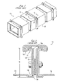
- FIGURES 1 and 2 A representative example of a duct connection system is illustrated in FIGURES 1 and 2.
- United States Patent No. 4,466,641 describes a duct connecting system of this type, known as the Transverse Duct Connector (TDC) system, which utilizes roll formed flanges on the ends of duct sections defining frames which are unitary or integral to the duct walls. In a preferred form of this system, upper and lower channels are formed in the flanges for receiving the edges of a corner connector.
- TDC Transverse Duct Connector
- the TDC system marketed by The Lockformer Company and Iowa Precision Industries, Inc., permits rapid connection of duct sections by snapping corner connectors into the frames and bolting the duct sections together across adjoining frames to produce a duct having superior strength.
- United States Patent No. 4,579,375 also describes a duct connection system utilizing duct sections having integral frames.
- the roll forming apparatus of the present invention while generally applicable to bending operations, is particularly useful for fabricating duct sections for use in these and other types of duct manufacturing systems.
- Another primary object of the present invention is to provide a roll forming apparatus which is adjustable to produce bends of different dimensions.
- Another object of the present invention is to provide a roll forming apparatus having adjustable roll forming stations.
- Another object of the present invention is to provide a roll forming apparatus which is quickly and easily adjustable and avoids the need for expensive and time consuming retooling operations.
- Another object of the present invention is to provide a roll forming apparatus having forming stations capable of being quickly adjusted between several predetermined settings.
- Another object of the present invention is to provide a roll forming apparatus which can be easily adjusted to produce duct flanges of various different predetermined heights.
- Another object of the present invention is to provide an adjustable forming roll and rollset which can be installed to retrofit existing non-adjustable roll forming apparatus.
- a novel roll forming station, rollset and machine including at least one forming station having top and bottom rolls including separate inner and outer sections.
- the effective dimensions of the rolls are adjustable by changing the distance between the inner and outer roll sections.
- At least one forming station includes inner roll sections which are axially movable in a dimension transverse to the metal advancing direction and parallel to the drive shafts. Thereby, the position of a bend on a workpiece can be adjusted.
- Any suitable mechanism can be provided for securing the forming rolls in a selected operating position.
- indexing means are also provided for accurately and reproducibly adjusting the inner roll sections between predetermined settings.
- a system of adjustable stops can be provided to variably limit the axial travel of the forming roll inner sections. This makes adjusting the rolls to frequently used settings fast and easy and avoids the need for fine tuning when resetting for a different bend dimension.
- the present invention provides an adjustable rollset including more than one adjustable forming station. Indexing means insure that each forming station of the rollset can be reproducibly adjusted to predetermined settings such that all are accurately coordinated to one another in each operating setting.
- the present invention can also include further components which are adjustable in coordination with the settings of the adjustable inner roll sections.
- the idler can be axially adjustable to accommodate the operating settings of adjacent adjustable forming stations.
- the present invention is particularly useful for forming duct flanges of different heights and is generally applicable to formation of all duct flange structures, including those described in the United States Patent Nos. 4,466,641 and 4,579,375, discussed above.
- the present invention is also generally useful for any other roll forming application.
- Duct joint 20 illustrates a duct connection wherein ducts or duct segments 22 and 24 are connected at their respective transverse ends.
- Duct segment 22 has roll formed upturned portion or flange 26 including channel 28 and bead 30 defining a second channel 32.
- the height of flange 26 is determined by the distance D between channels 28 and 32. Corner connector 34 is received by flange 26.
- the distance D can be adjusted by changing the position of bend 36 in relation to bend 38.
- the preferred embodiment of the present invention can be used to make duct sections of this or any other type wherein periodic adjustment of the bend dimensions is desired.
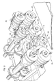
- roll forming apparatus 40 embodies the presently preferred manner of practicing the invention. While not necessary or limiting to the invention, rollformer 40 includes a total of fourteen forming stations, wherein the second through sixth stations are individually adjustable in order to provide different duct flange heights.
- FIGURE 3 is a fragmentary view showing the fourth, fifth and sixth forming stations designated 42, 44 and 46, respectively.
- FIGURE 3 also shows idler assembly 48 which is axially adjustable to register with the available positions of the forming stations.
- the adjustable forming stations of rollformer 40 are each constructed to move between each of three preset flange height settings, as described in greater detail hereafter.
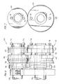
- roll forming station 44 is representative of the adjustable forming stations of rollformer 40.
- Station 44 has top roll 50 and bottom roll 52, located on drive shafts 54 and 56, respectively.
- Roll 50 has inner section 58 and outer section 60.
- Roll 52 has inner section 62 and outer section 64.
- Inner roll sections 58 and 62 define a bending region 69 and are adjacent to backing collars 66 and 68, respectively.
- Adjustability of station 44 is provided by inner roll sections 58 and 62, which are axially slidable as a unit on their respective drive shafts thereby changing the axial position of bending region 69.
- Bolts 70, 72, 74 and 76 secure the roll sections in desired operating settings and must be loosened in order to reposition the unit of inner roll sections 58 and 62.
- Forming rolls 50 and 52 preferably are prevented from rotation in relation to their respective drive shafts by any suitable means.
- station 44 preferably includes suitable means to secure inner roll sections 58 and 62 in different predetermined operating positions or settings. Therefore, the preferred embodiment includes a rotatable backing collar having a series of stops corresponding to preselected operating positions.
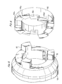
- rotatable backing collar 66 which cooperates with a rear face 78 of inner roll section 58.
- Collar 66 has a stepped profile including three repeating sets of three steps each, 80a-80c, and upper platform 80d. As seen in FIGURE 6, collar 66 has a mating interaction with rear face 78, which has three evenly spaced teeth 82.
- Steps 80a-80c provide alternate stops against which teeth 82 will selectively abut according to the rotational position of backing collar 66.
- backing collar 66 is provided with steps 80a-80c, wherein each successive step is 5 millimeters higher than the last. This configuration can be employed to fabricate duct flanges of 25, 30 and 35 millimeter heights, respectively.
- All of the adjustable roll forming stations of the apparatus are preferably constructed to provide identical backing collar settings in order to form a compatible set of forming stations which adjust in the same amounts to provide a desired bend at a desired location on a workpiece.
- the final forming station (not shown) of rollformer 40 is preferably provided with a different bottom roll corresponding to each different operating setting of the adjustable forming stations. Upon resetting the rolls, the final bottom roll is replaced in order to properly square the final form of a duct flange.
- the preferred embodiment also includes optional idler assembly 48, which is axially adjustable along track 83 to register properly with the forming roll settings.
- lockup bolts 84 and 86 secure assembly 48 in its operating positions and can be loosened in order to axially move the assembly.
- Dial 88 has three stops 90a-90c (90c not shown) of different predetermined lengths which correspond respectively to the available forming station settings 80a-80c. Dial 88 can be rotated to determine which stop is in the top position to act on assembly 48. Stops 90a-90c limit the axial travel of assembly 48 to three different predetermined settings, respectively, depending on the position of dial 88.
- rollformer 40 is an example of the preferred embodiment as applied to a specific roll forming operation.
- the basic structure of adjustable rollforming station 44 is generally applicable. Further, various modifications of this basic structure are available in accordance with the present invention.
- the number of adjustable forming stations is a matter of preference based on the particular bending application.
- the number and location of the teeth and stops is a matter of preference according to particular situations.
- the resetting mechanism itself can be inverted such that the rear faces of the inner forming roll sections have stepped profiles and the backing collars have teeth.
- the backing collars can be removable and replaceable to increase versatility.
- operating settings need not be limited to discreet stops.
- a backing collar can have a sloped profile providing an infinite number of operating settings.
Landscapes
- Engineering & Computer Science (AREA)
- Mechanical Engineering (AREA)
- Bending Of Plates, Rods, And Pipes (AREA)
- Diaphragms For Electromechanical Transducers (AREA)
- Glass Compositions (AREA)
- Ceramic Capacitors (AREA)
Applications Claiming Priority (2)
| Application Number | Priority Date | Filing Date | Title |
|---|---|---|---|
| US09/482,876 US6311534B1 (en) | 2000-01-14 | 2000-01-14 | Sheet metal bending apparatus |
| US482876 | 2000-01-14 |
Publications (3)
| Publication Number | Publication Date |
|---|---|
| EP1116530A2 true EP1116530A2 (de) | 2001-07-18 |
| EP1116530A3 EP1116530A3 (de) | 2003-08-20 |
| EP1116530B1 EP1116530B1 (de) | 2005-09-21 |
Family
ID=23917799
Family Applications (1)
| Application Number | Title | Priority Date | Filing Date |
|---|---|---|---|
| EP00114252A Expired - Lifetime EP1116530B1 (de) | 2000-01-14 | 2000-07-03 | Blechbiegevorrichtung |
Country Status (6)
| Country | Link |
|---|---|
| US (1) | US6311534B1 (de) |
| EP (1) | EP1116530B1 (de) |
| AT (1) | ATE304904T1 (de) |
| AU (1) | AU782829B2 (de) |
| DE (1) | DE60022731T2 (de) |
| ES (1) | ES2247985T3 (de) |
Families Citing this family (3)
| Publication number | Priority date | Publication date | Assignee | Title |
|---|---|---|---|---|
| US20080223104A1 (en) * | 2006-03-22 | 2008-09-18 | Lavalliere Richard R | Crimping tool and method for duct connectors |
| US7360390B2 (en) * | 2006-03-22 | 2008-04-22 | Lavalliere Richard R | Method for securing corner connectors within a duct section |
| US8561448B2 (en) | 2008-10-01 | 2013-10-22 | Mestek Machinery, Inc. | Duct blank seam and apparatus for making a duct blank seam |
Family Cites Families (13)
| Publication number | Priority date | Publication date | Assignee | Title |
|---|---|---|---|---|
| US1078240A (en) * | 1913-11-11 | George H Barbour | Rolling-mill. | |
| US865908A (en) * | 1906-12-18 | 1907-09-10 | Godfrey Benington Johnson | Machine for corrugating sheet metal. |
| US851451A (en) * | 1907-01-29 | 1907-04-23 | Charles Friedrich Steiber | Machine-rolls. |
| JPS4737833Y1 (de) * | 1969-09-30 | 1972-11-15 | ||
| US4269055A (en) * | 1979-04-10 | 1981-05-26 | Eugene W. Sivachenko | Large profile sheet metal corrugator |
| JPS57209722A (en) * | 1981-06-22 | 1982-12-23 | Nippon Kokan Kk <Nkk> | Breakdown roll stand for manufacturing electric welded steel tube |
| US4526024A (en) * | 1982-07-09 | 1985-07-02 | Toti Andrew J | Apparatus for forming elongated sheet metal panels |
| US4899566A (en) * | 1988-09-06 | 1990-02-13 | Knudson Gary Art | Apparatus for making gutters and the like |
| GB2279023B (en) * | 1993-04-27 | 1996-06-05 | Ward Building Systems Ltd | Rolling mill |
| US5394722A (en) * | 1993-08-17 | 1995-03-07 | Meyer; Bruce E. | Apparatus for forming profiles on strip materials |
| US5599264A (en) * | 1995-02-08 | 1997-02-04 | Kawasaki Steel Corporation | Roller width adjusting device for a divided type molding roller |
| JP3198877B2 (ja) * | 1995-07-24 | 2001-08-13 | 三菱マテリアル株式会社 | 簡易クランプ式圧延ロール |
| US6041632A (en) * | 1997-09-10 | 2000-03-28 | Kawasaki Steel Corporation | Pipe forming roll apparatus and method |
-
2000
- 2000-01-14 US US09/482,876 patent/US6311534B1/en not_active Expired - Fee Related
- 2000-06-27 AU AU42706/00A patent/AU782829B2/en not_active Ceased
- 2000-07-03 EP EP00114252A patent/EP1116530B1/de not_active Expired - Lifetime
- 2000-07-03 DE DE60022731T patent/DE60022731T2/de not_active Expired - Fee Related
- 2000-07-03 ES ES00114252T patent/ES2247985T3/es not_active Expired - Lifetime
- 2000-07-03 AT AT00114252T patent/ATE304904T1/de not_active IP Right Cessation
Also Published As
| Publication number | Publication date |
|---|---|
| EP1116530A3 (de) | 2003-08-20 |
| AU782829B2 (en) | 2005-09-01 |
| US6311534B1 (en) | 2001-11-06 |
| EP1116530B1 (de) | 2005-09-21 |
| DE60022731D1 (de) | 2006-02-02 |
| ES2247985T3 (es) | 2006-03-16 |
| AU4270600A (en) | 2001-07-19 |
| DE60022731T2 (de) | 2006-06-29 |
| ATE304904T1 (de) | 2005-10-15 |
Similar Documents
| Publication | Publication Date | Title |
|---|---|---|
| US6148654A (en) | Convertible roll forming apparatus | |
| US9676018B2 (en) | Method and apparatus for forming the profile of deformable materials and deformable tubular sections | |
| DE69710610T2 (de) | Vorrichtung zum rollformen von blechformpfetten oder ähnlichem aus metallplatten | |
| US20170326610A1 (en) | Apparatus and method for forming a screw flight | |
| US6311534B1 (en) | Sheet metal bending apparatus | |
| WO1984004263A1 (fr) | Procede et dispositif de calandrage de sections comportant un rebord | |
| US6109083A (en) | Device for continuously rolling a sheet-metal strip into a profile with profile limbs of straight cross section, in particular for producing longitudinally welded rectangular tubes | |
| JP3848945B2 (ja) | 可変幅ロール成形装置 | |
| DE19839614A1 (de) | Biegewälz-Verfahren zur Herstellung von Elektro-Verbund-Röhren mittels Biegewälz-Lager | |
| EP0339064B1 (de) | Walzstrasse | |
| DE102005000893A1 (de) | Verfahren zum Herstellen eines Strukturbauteils für ein Kraftfahrzeug und Vorrichtung zur Durchführung des Verfahrens | |
| RU2518019C2 (ru) | Роликовая профилирующая машина | |
| EP0403131B1 (de) | Biegevorrichtung | |
| CA2176281C (en) | Roll former with side edge control | |
| US11247259B2 (en) | Forming roller adjustment system | |
| JP2851512B2 (ja) | フランジを有する形材の圧延装置列および圧延方法 | |
| JP2001030003A (ja) | H形鋼のユニバーサル圧延方法 | |
| JP2006315075A (ja) | 格子体の構成部品及びその製造方法 | |
| JPH0399702A (ja) | フランジを有する形材の熱間圧延方法 | |
| EP1308222A2 (de) | Rohrschweissvorrichtung | |
| UA45229A (uk) | Пристрій для виготовлення ободів коліс транспортно-технологічних систем | |
| NZ620017B2 (en) | Apparatus and method for forming a screw flight |
Legal Events
| Date | Code | Title | Description |
|---|---|---|---|
| PUAI | Public reference made under article 153(3) epc to a published international application that has entered the european phase |
Free format text: ORIGINAL CODE: 0009012 |
|
| AK | Designated contracting states |
Kind code of ref document: A2 Designated state(s): AT BE CH CY DE DK ES FI FR GB GR IE IT LI LU MC NL PT SE |
|
| AX | Request for extension of the european patent |
Free format text: AL;LT;LV;MK;RO;SI |
|
| RAP1 | Party data changed (applicant data changed or rights of an application transferred) |
Owner name: MET-COIL SYSTEMS CORPORATION |
|
| PUAL | Search report despatched |
Free format text: ORIGINAL CODE: 0009013 |
|
| RIC1 | Information provided on ipc code assigned before grant |
Ipc: 7B 21B 31/18 B Ipc: 7B 21B 27/02 B Ipc: 7B 21D 5/08 A Ipc: 7B 21D 5/12 B |
|
| AK | Designated contracting states |
Designated state(s): AT BE CH CY DE DK ES FI FR GB GR IE IT LI LU MC NL PT SE |
|
| AX | Request for extension of the european patent |
Extension state: AL LT LV MK RO SI |
|
| 17P | Request for examination filed |
Effective date: 20040220 |
|
| AKX | Designation fees paid |
Designated state(s): AT BE CH CY DE DK ES FI FR GB GR IE IT LI LU MC NL PT SE |
|
| 17Q | First examination report despatched |
Effective date: 20040812 |
|
| GRAP | Despatch of communication of intention to grant a patent |
Free format text: ORIGINAL CODE: EPIDOSNIGR1 |
|
| GRAS | Grant fee paid |
Free format text: ORIGINAL CODE: EPIDOSNIGR3 |
|
| GRAA | (expected) grant |
Free format text: ORIGINAL CODE: 0009210 |
|
| AK | Designated contracting states |
Kind code of ref document: B1 Designated state(s): AT BE CH CY DE DK ES FI FR GB GR IE IT LI LU MC NL PT SE |
|
| PG25 | Lapsed in a contracting state [announced via postgrant information from national office to epo] |
Ref country code: LI Free format text: LAPSE BECAUSE OF FAILURE TO SUBMIT A TRANSLATION OF THE DESCRIPTION OR TO PAY THE FEE WITHIN THE PRESCRIBED TIME-LIMIT Effective date: 20050921 Ref country code: FI Free format text: LAPSE BECAUSE OF FAILURE TO SUBMIT A TRANSLATION OF THE DESCRIPTION OR TO PAY THE FEE WITHIN THE PRESCRIBED TIME-LIMIT Effective date: 20050921 Ref country code: BE Free format text: LAPSE BECAUSE OF FAILURE TO SUBMIT A TRANSLATION OF THE DESCRIPTION OR TO PAY THE FEE WITHIN THE PRESCRIBED TIME-LIMIT Effective date: 20050921 Ref country code: CH Free format text: LAPSE BECAUSE OF FAILURE TO SUBMIT A TRANSLATION OF THE DESCRIPTION OR TO PAY THE FEE WITHIN THE PRESCRIBED TIME-LIMIT Effective date: 20050921 |
|
| REG | Reference to a national code |
Ref country code: GB Ref legal event code: FG4D |
|
| REG | Reference to a national code |
Ref country code: CH Ref legal event code: EP |
|
| REG | Reference to a national code |
Ref country code: IE Ref legal event code: FG4D |
|
| REF | Corresponds to: |
Ref document number: 60022731 Country of ref document: DE Date of ref document: 20051027 Kind code of ref document: P |
|
| PG25 | Lapsed in a contracting state [announced via postgrant information from national office to epo] |
Ref country code: SE Free format text: LAPSE BECAUSE OF FAILURE TO SUBMIT A TRANSLATION OF THE DESCRIPTION OR TO PAY THE FEE WITHIN THE PRESCRIBED TIME-LIMIT Effective date: 20051221 Ref country code: GR Free format text: LAPSE BECAUSE OF FAILURE TO SUBMIT A TRANSLATION OF THE DESCRIPTION OR TO PAY THE FEE WITHIN THE PRESCRIBED TIME-LIMIT Effective date: 20051221 Ref country code: DK Free format text: LAPSE BECAUSE OF FAILURE TO SUBMIT A TRANSLATION OF THE DESCRIPTION OR TO PAY THE FEE WITHIN THE PRESCRIBED TIME-LIMIT Effective date: 20051221 |
|
| REF | Corresponds to: |
Ref document number: 60022731 Country of ref document: DE Date of ref document: 20060202 Kind code of ref document: P |
|
| PG25 | Lapsed in a contracting state [announced via postgrant information from national office to epo] |
Ref country code: PT Free format text: LAPSE BECAUSE OF FAILURE TO SUBMIT A TRANSLATION OF THE DESCRIPTION OR TO PAY THE FEE WITHIN THE PRESCRIBED TIME-LIMIT Effective date: 20060221 |
|
| REG | Reference to a national code |
Ref country code: ES Ref legal event code: FG2A Ref document number: 2247985 Country of ref document: ES Kind code of ref document: T3 |
|
| REG | Reference to a national code |
Ref country code: CH Ref legal event code: PL |
|
| ET | Fr: translation filed | ||
| PG25 | Lapsed in a contracting state [announced via postgrant information from national office to epo] |
Ref country code: IE Free format text: LAPSE BECAUSE OF NON-PAYMENT OF DUE FEES Effective date: 20060703 |
|
| PLBE | No opposition filed within time limit |
Free format text: ORIGINAL CODE: 0009261 |
|
| STAA | Information on the status of an ep patent application or granted ep patent |
Free format text: STATUS: NO OPPOSITION FILED WITHIN TIME LIMIT |
|
| PG25 | Lapsed in a contracting state [announced via postgrant information from national office to epo] |
Ref country code: MC Free format text: LAPSE BECAUSE OF NON-PAYMENT OF DUE FEES Effective date: 20060731 |
|
| 26N | No opposition filed |
Effective date: 20060622 |
|
| REG | Reference to a national code |
Ref country code: IE Ref legal event code: MM4A |
|
| PGFP | Annual fee paid to national office [announced via postgrant information from national office to epo] |
Ref country code: DE Payment date: 20070719 Year of fee payment: 8 |
|
| PGFP | Annual fee paid to national office [announced via postgrant information from national office to epo] |
Ref country code: ES Payment date: 20070727 Year of fee payment: 8 |
|
| PGFP | Annual fee paid to national office [announced via postgrant information from national office to epo] |
Ref country code: AT Payment date: 20070716 Year of fee payment: 8 |
|
| PGFP | Annual fee paid to national office [announced via postgrant information from national office to epo] |
Ref country code: GB Payment date: 20070720 Year of fee payment: 8 |
|
| PGFP | Annual fee paid to national office [announced via postgrant information from national office to epo] |
Ref country code: IT Payment date: 20070725 Year of fee payment: 8 Ref country code: NL Payment date: 20070716 Year of fee payment: 8 |
|
| PGFP | Annual fee paid to national office [announced via postgrant information from national office to epo] |
Ref country code: FR Payment date: 20070710 Year of fee payment: 8 |
|
| PG25 | Lapsed in a contracting state [announced via postgrant information from national office to epo] |
Ref country code: LU Free format text: LAPSE BECAUSE OF NON-PAYMENT OF DUE FEES Effective date: 20060703 |
|
| PG25 | Lapsed in a contracting state [announced via postgrant information from national office to epo] |
Ref country code: CY Free format text: LAPSE BECAUSE OF FAILURE TO SUBMIT A TRANSLATION OF THE DESCRIPTION OR TO PAY THE FEE WITHIN THE PRESCRIBED TIME-LIMIT Effective date: 20050921 |
|
| GBPC | Gb: european patent ceased through non-payment of renewal fee |
Effective date: 20080703 |
|
| NLV4 | Nl: lapsed or anulled due to non-payment of the annual fee |
Effective date: 20090201 |
|
| PG25 | Lapsed in a contracting state [announced via postgrant information from national office to epo] |
Ref country code: AT Free format text: LAPSE BECAUSE OF NON-PAYMENT OF DUE FEES Effective date: 20080703 Ref country code: DE Free format text: LAPSE BECAUSE OF NON-PAYMENT OF DUE FEES Effective date: 20090203 |
|
| REG | Reference to a national code |
Ref country code: FR Ref legal event code: ST Effective date: 20090331 |
|
| PG25 | Lapsed in a contracting state [announced via postgrant information from national office to epo] |
Ref country code: NL Free format text: LAPSE BECAUSE OF NON-PAYMENT OF DUE FEES Effective date: 20090201 |
|
| PG25 | Lapsed in a contracting state [announced via postgrant information from national office to epo] |
Ref country code: GB Free format text: LAPSE BECAUSE OF NON-PAYMENT OF DUE FEES Effective date: 20080703 |
|
| PG25 | Lapsed in a contracting state [announced via postgrant information from national office to epo] |
Ref country code: IT Free format text: LAPSE BECAUSE OF NON-PAYMENT OF DUE FEES Effective date: 20080703 Ref country code: FR Free format text: LAPSE BECAUSE OF NON-PAYMENT OF DUE FEES Effective date: 20080731 |
|
| REG | Reference to a national code |
Ref country code: ES Ref legal event code: FD2A Effective date: 20080704 |
|
| PG25 | Lapsed in a contracting state [announced via postgrant information from national office to epo] |
Ref country code: ES Free format text: LAPSE BECAUSE OF NON-PAYMENT OF DUE FEES Effective date: 20080704 |