EP1116604A2 - Bandages pneumatiques - Google Patents
Bandages pneumatiques Download PDFInfo
- Publication number
- EP1116604A2 EP1116604A2 EP01300266A EP01300266A EP1116604A2 EP 1116604 A2 EP1116604 A2 EP 1116604A2 EP 01300266 A EP01300266 A EP 01300266A EP 01300266 A EP01300266 A EP 01300266A EP 1116604 A2 EP1116604 A2 EP 1116604A2
- Authority
- EP
- European Patent Office
- Prior art keywords
- slant
- land part
- groove
- land
- pneumatic tire
- Prior art date
- Legal status (The legal status is an assumption and is not a legal conclusion. Google has not performed a legal analysis and makes no representation as to the accuracy of the status listed.)
- Granted
Links
- 230000007423 decrease Effects 0.000 claims description 11
- 230000002349 favourable effect Effects 0.000 description 14
- XLYOFNOQVPJJNP-UHFFFAOYSA-N water Substances O XLYOFNOQVPJJNP-UHFFFAOYSA-N 0.000 description 8
- 238000010276 construction Methods 0.000 description 3
- 230000000694 effects Effects 0.000 description 2
- 230000001788 irregular Effects 0.000 description 2
- 230000000593 degrading effect Effects 0.000 description 1
- 230000006866 deterioration Effects 0.000 description 1
- 238000011156 evaluation Methods 0.000 description 1
- 238000012986 modification Methods 0.000 description 1
- 230000004048 modification Effects 0.000 description 1
- 230000003014 reinforcing effect Effects 0.000 description 1
Images


Classifications
-
- B—PERFORMING OPERATIONS; TRANSPORTING
- B60—VEHICLES IN GENERAL
- B60C—VEHICLE TYRES; TYRE INFLATION; TYRE CHANGING; CONNECTING VALVES TO INFLATABLE ELASTIC BODIES IN GENERAL; DEVICES OR ARRANGEMENTS RELATED TO TYRES
- B60C11/00—Tyre tread bands; Tread patterns; Anti-skid inserts
- B60C11/03—Tread patterns
- B60C11/13—Tread patterns characterised by the groove cross-section, e.g. for buttressing or preventing stone-trapping
- B60C11/1376—Three dimensional block surfaces departing from the enveloping tread contour
- B60C11/1392—Three dimensional block surfaces departing from the enveloping tread contour with chamfered block edges
-
- B—PERFORMING OPERATIONS; TRANSPORTING
- B60—VEHICLES IN GENERAL
- B60C—VEHICLE TYRES; TYRE INFLATION; TYRE CHANGING; CONNECTING VALVES TO INFLATABLE ELASTIC BODIES IN GENERAL; DEVICES OR ARRANGEMENTS RELATED TO TYRES
- B60C11/00—Tyre tread bands; Tread patterns; Anti-skid inserts
- B60C11/03—Tread patterns
- B60C11/0302—Tread patterns directional pattern, i.e. with main rolling direction
-
- B—PERFORMING OPERATIONS; TRANSPORTING
- B60—VEHICLES IN GENERAL
- B60C—VEHICLE TYRES; TYRE INFLATION; TYRE CHANGING; CONNECTING VALVES TO INFLATABLE ELASTIC BODIES IN GENERAL; DEVICES OR ARRANGEMENTS RELATED TO TYRES
- B60C11/00—Tyre tread bands; Tread patterns; Anti-skid inserts
- B60C11/03—Tread patterns
- B60C11/0306—Patterns comprising block rows or discontinuous ribs
- B60C11/0309—Patterns comprising block rows or discontinuous ribs further characterised by the groove cross-section
-
- B—PERFORMING OPERATIONS; TRANSPORTING
- B60—VEHICLES IN GENERAL
- B60C—VEHICLE TYRES; TYRE INFLATION; TYRE CHANGING; CONNECTING VALVES TO INFLATABLE ELASTIC BODIES IN GENERAL; DEVICES OR ARRANGEMENTS RELATED TO TYRES
- B60C11/00—Tyre tread bands; Tread patterns; Anti-skid inserts
- B60C11/03—Tread patterns
- B60C11/13—Tread patterns characterised by the groove cross-section, e.g. for buttressing or preventing stone-trapping
-
- B—PERFORMING OPERATIONS; TRANSPORTING
- B60—VEHICLES IN GENERAL
- B60C—VEHICLE TYRES; TYRE INFLATION; TYRE CHANGING; CONNECTING VALVES TO INFLATABLE ELASTIC BODIES IN GENERAL; DEVICES OR ARRANGEMENTS RELATED TO TYRES
- B60C11/00—Tyre tread bands; Tread patterns; Anti-skid inserts
- B60C11/03—Tread patterns
- B60C2011/0337—Tread patterns characterised by particular design features of the pattern
- B60C2011/0339—Grooves
- B60C2011/0374—Slant grooves, i.e. having an angle of about 5 to 35 degrees to the equatorial plane
Definitions
- This invention relates to a pneumatic tire improving drainage performance and steering stability and reducing noise without sacrificing other tire performances.
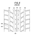
- a tread pattern of a pneumatic tire e.g. passenger car tire is usual to be defined by circumferential grooves 101-103 extending in parallel to an equatorial plane of the tire and a plurality of slant grooves 104-106 opening to the circumferential grooves 101, 102 and extending obliquely with respect to the equatorial plane toward each end of a tread portion.
- an object of the invention to provide a pneumatic tire wherein all of drainage performance, steering stability and noise can be improved to satisfactory levels by adopting a tread pattern having a rib-shaped main land part arranged in a central region of a tread portion and rationalizing a plane shape (ground contact face) of a first slant land part defined by main slant grooves and arranging a first auxiliary land part of an adequate form between the rib-shaped main land part and the main slant groove.
- a tread pattern useful for the reduction of noise i.e. a tread pattern that a first auxiliary land part of an adequate form is arranged between a rib-shaped main land part and a main slant groove so as not to open the main slant groove to a first circumferential fine groove at least located in a central region, and rationalizing a plane shape (ground contact face) of a first slant land part defined by the main slant grooves.
- a pneumatic tire comprising a tread portion divided into a central region and both side regions, at least one rib-shaped main land part formed in the central region and extending substantially in parallel to an equatorial plane of the tire, a plurality of main slant grooves extending obliquely from the central region toward each tread end of the tread portion with respect to the equatorial plane to form first slant land parts among these main slant grooves, in which the first slant land part has a plane form of approximately a triangle gradually increasing a width of the land part from a side of the equatorial plane toward a side of the tread end, and a first auxiliary land part having such a slope that a height of the land part gradually decreases toward a groove bottom of the main slant groove is arranged between the rib-shaped main land part and the main slant groove.
- central region used herein means a region centering on a position of the equatorial plane and corresponding to 5-50% of a tread width TW, and the term “both side regions” are regions located at both sides of the central region.
- the rib-shaped main land part is favorable to be integrally united with the first slant land part.
- the first circumferential fine groove is favorable to have a sectional shape that a groove width becomes wide at a position of the groove bottom and becomes narrow at a position of a ground contact face of the tread portion.
- the first circumferential fine groove is favorable to have a sectional shape of approximately a conical flask.
- a plurality of slant sub-grooves each extending obliquely from the side region of the tread portion toward the tread end with respect to the equatorial plane are arranged to form second slant land parts among these slant sub-grooves in which a land width gradually increases toward the tread end.
- the stiffness of the land part is important, it is favorable to integrally unite the first slant land part with the second slant land part.
- a second auxiliary land part having such a slope that a land height gradually decreases toward the groove bottom of the slant sub-groove is arranged between the first slant land part and the slant sub-groove.
- a second circumferential fine groove extending substantially in parallel to the equatorial plane and having a sectional shape similar to that of the first circumferential fine groove is arranged at a boundary between the first slant land part and the second slant land part.
- a first joint land part connecting the first slant land parts to each other and having an extremely narrow width is arranged along a groove wall of the second circumferential fine groove facing to the side of the equatorial plane and a third auxiliary land part having such a slope that a land height gradually decreases toward a groove bottom of the main slant groove is arranged between the first joint part and the main slant groove.
- an angle between the ground contact face of the rib-shaped main land part and the slope of the first auxiliary land part, an angle between the ground contact face of the first slant land part and the slope of the second auxiliary land part and an angle between the ground contact face of the first joint part and the slope of the third auxiliary land part are within a range of 135-170°, respectively.
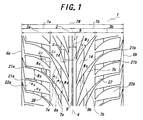
- Fig. 1 a typical embodiment of a tread pattern in the pneumatic tire according to the invention, wherein numeral 1 is a tread portion, numeral 2 a central region, numerals 3a, 3b side regions, numeral 4 an equatorial plane of the tire, numeral 5 a rib-shaped main land part, numeral 6a, 6b tread ends, numerals 7a, 7b main slant grooves, numerals 8a, 8b first slant land parts, and numeral 14 a first auxiliary land part.
- numeral 1 is a tread portion
- numeral 2 a central region
- numeral 4 an equatorial plane of the tire
- numeral 5 a rib-shaped main land part
- numeral 6a, 6b tread ends numerals 7a, 7b main slant grooves
- numerals 8a, 8b first slant land parts numeral 14 a first auxiliary land part.
- At least one rib-shaped land part 5 extending substantially in parallel to the equatorial plane 4 is arranged in the central region 2 of the tread portion 1 constituted with the central region 2 and side regions 3a, 3b, and a plurality of main slant grooves 7a, 7b extending obliquely from the central region 2 toward the tread end 6a, 6b with respect to the equatorial plane 4 are arranged to form first slant land parts 8a, 8b between the main slant grooves 7a, 7b and/or 7b, 7b.
- a main feature in the construction of the invention lies in that a tread pattern useful for the noise reduction, i.e. a tread pattern wherein a first auxiliary land part 14 of an adequate shape is disposed between the rib-shaped main land part 5 and the slant groove (concretely main slant groove 7a, 7b) and the slant groove is not opened to a circumferential groove at least located in the central region 2 (concretely a first circumferential fine groove 9 as shown in Fig.
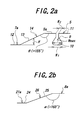
- first slant land part 8a, 8b has a plane form of approximately such a triangle that a land width W4 gradually increases from the side of the equatorial plane 4 toward the side of the tread end 6a, 6b, and a first auxiliary land part 14 having such a slope that a land height H gradually decreases toward the groove bottom of the main slant groove 7a, 7b is arranged between the rib-shaped main land part 5 and the main slant groove 7a, 7b (see Fig. 2a).
- the rib-shaped main land part 5 in the central region 2 of the tread portion 1 can be smoothly rotated the tire while contacting with ground surface, whereby the pattern noise can be controlled, and the stiffness of the tread portion 1 in the central region 2 can sufficiently be enhanced to improve the steering stability, especially a handling response in the steering at a very slight angle.
- the adoption of the tread pattern that the main slant groove 7a, 7b is not opened to the circumferential groove at least arranged in the central region 2 (concretely a first circumferential fine groove 9) is advantageous for the noise reduction.
- an area of a portion of the first slant land part 8a, 8b located side the equatorial plane 4 is made narrower and an area of a portion located side the tread end 6a, 6b is made wider, whereby the stiffness of the land part at the side region 3a, 3b becomes higher to improve the steering stability and also a negative ratio in the central region 2 is made relatively larger than that of the side region 3a, 3b to improve the drainage performance and hence the steering stability and the drainage performance can be balancedly improved.
- the first auxiliary land part 14 having such a slope 13 that a land height H gradually decreases toward the groove bottom 12 of the main slant groove 7a, 7b is arranged between the rib-shaped main land part 5 and the main slant groove 7a, 7b, whereby the rib-shaped main land part 5 is reinforced to more increase the stiffness and hence the steering stability can be more improved and water located in the central region 2 during the contact with ground surface can smoothly be flowed into the main slant groove 7a, 7b along the slope 13 of the first auxiliary land part 14 without causing disorder to more improve the drainage performance.
- an angle ⁇ between a ground contact face 5a of the rib-shaped main land part 5 and a slope 13 of the first auxiliary land part 14 is preferably within a range of 135-170°.
- the angle ⁇ is less than 135°, there is caused a fear that an effect of sufficiently reinforcing the stiffness is not obtained, while when the angle ⁇ exceeds 170°, the groove volume of the main slant groove 7a, 7b becomes extremely small and there is caused a fear of degrading the drainage performance.
- the rib-shaped main land part 5 may be integrally united with the first slant land part 8a, 8b, whereby the stiffness of the whole land part inclusive of the rib-shaped main land part 5 located in the central region 2 can be increased to advantageously improve the steering stability.
- a first circumferential fine groove 9 may be arranged in the rib-shaped main land part 5 as shown in Fig. 1, whereby the ground contacting property in the central region 2 of the tread portion 1 can be enhanced.
- the first circumferential fine groove 9 is not opened to the main slant groove 7a, 7b, so that water existing in the central region 2 of the tread portion 1 during the contacting of the tire with ground surface is entrapped in the first circumferential fine groove 9 and rapidly discharged along the first circumferential fine groove 9 in front-back direction of the tire without causing disorder state in the fine groove and hence the drainage performance is effectively enhanced.
- the first circumferential fine groove 9 is made to have such a sectional shape that a groove width W 1 at a position 10 of the groove bottom becomes wide and a groove width W 2 at a position 11 of a ground contact face of the tread portion becomes narrow, whereby the groove volume of the first circumferential fine groove 9 can be increased to more effectively improve the drainage performance.
- the wearing of the tread portion 1 proceeds to a certain level, it tends to decrease the groove volume to lower the drainage performance.
- the first circumferential fine groove 9 is rendered into the above sectional shape, the lowering of the drainage performance can be made up.
- a width-wide circumferential groove is not arranged in the tread portion 1, so that the occurrence of high-frequency noise due to columnar resonance is less, which advantageously acts to the noise reduction.
- the first circumferential fine groove 9 is favorable to have a sectional shape of approximately a conical flask as shown in Fig. 2a.
- first slant land part 8a, 8b is integrally united with a second slant land part 22a, 22b as shown in Fig. 1, there is provided an effect of more reducing the pattern noise.
- irregular wear of the second slant land part 22a, 22b (more concretely heel and toe wear) can be suppressed, the deterioration of noise after the progress of the wearing can also be controlled.
- a plurality of slant sub-grooves 21a, 21b each extending obliquely from the side region 3a, 3b of the tread portion 1 toward the tread end 6a, 6b with respect to the equatorial plane 4 are arranged to define a second slant land part 22a, 22b gradually increasing a land width toward the tread end 6a, 6b between these slant sub-grooves 21a, 21b.
- a second auxiliary land part 26 having such a slope 25 that a land height H gradually decreases toward a groove bottom 24 of the slant sub-groove 21a, 21b is arranged between the first slant land part 8a, 8b and the slant sub-groove 21a, 21b.
- a second circumferential fine groove 15a, 15b extending substantially in parallel to the equatorial plane 4 and having a sectional shape similar to that of the first circumferential fine groove 9 is arranged at a position of a boundary between the first slant land part 8a, 8b and the second slant land part 22a, 22b.
- a second joint land part 23 of an extremely narrow width connecting the second slant land parts 22a, 22b to each other is arranged along a groove wall 17 of the second circumferential fine groove 15a, 15b located at the side of the tread end 6a, 6b and the second auxiliary land part 26 is disposed between the second joint land part 23 and the slant sub-groove 21a, 21b to reinforce the second joint land part 23, whereby the stiffness becomes more higher to more improve the steering stability and also water can smoothly be flowed into the slant sub-groove 21a, 21b without causing disorder in the sub-groove to thereby more improve the drainage performance.
- an angle ⁇ between a ground contact face 23a of the second joint land part 23 and a slope 25 of the second auxiliary land part 26 is favorable to be within a range of 135-170° from the same reason as in the case of the angle ⁇ .
- a first joint land part 18 of an extremely narrow width connecting the first slant land parts 8a, 8b to each other is arranged along a groove wall 16 of the second circumferential fine groove 15a, 15b located at the side of the equatorial plane 4 and a third auxiliary land part 20 having a slope 19 that a land height H gradually decreases toward the groove bottom 12 of the main slant groove 7a, 7b is arranged between the first joint part 18 and the main slant groove 7a, 7b as shown in Fig. 4c, whereby the stiffness is increased while maintaining the negative ratio on the surface to thereby improve the steering stability and noise reduction while suppressing the lowering of the drainage performance.
- an angle ⁇ between a ground contact face 18a of the first joint land part 18 and the slope 19 of the third auxiliary land part 20 is favorable to be within a range of 135-170°.
- the angle ⁇ is less than 135°, the sufficient stiffness is not obtained, while when it exceeds 170°, the sufficient groove volume is not obtained.
- the main slant grooves 7a, 7b are arranged in a direction successively entering into the ground contact region from the side of the equatorial plane 4 toward the respective tread end 6a, 6b to form so-called directional pattern as shown in Fig. 1, which is favorable in a point that the sufficient drainage performance is obtained.
- a pneumatic tire having a tread pattern shown in Fig. 1 and a tire size of PSR205/55R16, in which dimensions of a rib-shaped land part, first circumferential fine groove, main slant groove, first slant land part, first auxiliary land part and the like are shown in Table 1. Moreover, the tire structure other than the tread portion is substantially the same as in the usual pneumatic tire for passenger car.
- a pneumatic tire having a tread pattern shown in Fig. 3 and a tire size of PSR205/55R16, in which dimensions of a rib-shaped land part, first circumferential fine groove, main slant groove, first slant land part, first auxiliary land part and the like are shown in Table 2.
- a conventional pneumatic tire having a tread pattern shown in Fig. 5 and a tire size of PSR205/55R16, in which dimensions of circumferential grooves 101-103, slant grooves 104-106 and the like are shown in Table 3.
- Groove width (mm) Groove angle (°)
- Groove depth (mm) Circumferential groove 101 8 0 8 Circumferential groove 102 7 0 8 Circumferential groove 103 3 0 8 Slant groove 104 4 80 6.5 Slant groove 105 4.5-5.0 50-70 6.5 Slant groove 106 5 75 6.5
- Each of the above tires is mounted onto an approved rim (61/2JJ) and inflated under an internal pressure of 230 kPa and subjected to the following actual running test under a load corresponding to two crew members.
- the drainage performance is evaluated in each of straight running and cornering.
- the drainage performance in the straight running is evaluated by measuring a limit speed in the occurrence of hydroplaning phenomenon when the tire is running straightforward on a road surface having a water depth of 5 mm.
- the drainage performance in the cornering is evaluated by measuring a lateral G in the occurrence of hydroplaning when the tire is run on a road surface having a radius of 80 m and a water depth of 5 mm.
- the steering stability is evaluated by a feeling of a test driver when the vehicle is run on a circuit course of dry state under various sport running modes.
- the pattern noise is evaluated by a feeling of a test driver on an indoor noise when the vehicle is run by inertia from a speed of 100 km/h on a straight smooth road surface.
- each numerical value of the drainage performances A and B, steering stability and pattern noise in Table 4 is represented by an index on the basis that the conventional example is 100, in which the larger the index value, the better the property.
- Conventional Example Example 1 Example 2
- Drainage performance A 100 120 115 105 Drainage performance B 100 120 115 110 Steering stability 100 120 120 125 Pattern noise 100 120 125 130
- the tires of Examples 1-3 are excellent in the drainage performance and the steering stability and the reduction of pattern noise as compared with the conventional tire.
- pneumatic tires having excellent drainage performance and steering stability and low noise without sacrificing the other tire performances.
Landscapes
- Engineering & Computer Science (AREA)
- Mechanical Engineering (AREA)
- Tires In General (AREA)
Applications Claiming Priority (2)
| Application Number | Priority Date | Filing Date | Title |
|---|---|---|---|
| JP2000007872 | 2000-01-17 | ||
| JP2000007872A JP4615655B2 (ja) | 2000-01-17 | 2000-01-17 | 空気入りタイヤ |
Publications (3)
| Publication Number | Publication Date |
|---|---|
| EP1116604A2 true EP1116604A2 (fr) | 2001-07-18 |
| EP1116604A3 EP1116604A3 (fr) | 2001-11-14 |
| EP1116604B1 EP1116604B1 (fr) | 2005-09-14 |
Family
ID=18536231
Family Applications (1)
| Application Number | Title | Priority Date | Filing Date |
|---|---|---|---|
| EP01300266A Expired - Lifetime EP1116604B1 (fr) | 2000-01-17 | 2001-01-12 | Bandages pneumatiques |
Country Status (5)
| Country | Link |
|---|---|
| US (1) | US6799616B2 (fr) |
| EP (1) | EP1116604B1 (fr) |
| JP (1) | JP4615655B2 (fr) |
| DE (1) | DE60113311T2 (fr) |
| ES (1) | ES2248236T3 (fr) |
Cited By (5)
| Publication number | Priority date | Publication date | Assignee | Title |
|---|---|---|---|---|
| EP2095975A1 (fr) * | 2008-02-29 | 2009-09-02 | The Yokohama Rubber Co., Ltd. | Pneu |
| EP2095974A1 (fr) * | 2008-02-29 | 2009-09-02 | The Yokohama Rubber Co., Ltd. | Pneu |
| CN107053958A (zh) * | 2015-10-30 | 2017-08-18 | 东洋橡胶工业株式会社 | 充气轮胎 |
| EP3552847A1 (fr) * | 2018-04-11 | 2019-10-16 | Sumitomo Rubber Industries, Ltd. | Pneumatique |
| CN111936323A (zh) * | 2018-03-26 | 2020-11-13 | 横滨橡胶株式会社 | 充气轮胎 |
Families Citing this family (10)
| Publication number | Priority date | Publication date | Assignee | Title |
|---|---|---|---|---|
| JP4580387B2 (ja) * | 2004-05-27 | 2010-11-10 | 株式会社ブリヂストン | 空気入りタイヤ |
| JP4505290B2 (ja) * | 2004-09-07 | 2010-07-21 | 株式会社ブリヂストン | 空気入りタイヤ |
| MX2011002468A (es) * | 2008-09-11 | 2011-04-05 | Michelin Rech Tech | Llanta para neumatico de area superficial variable y neumatico. |
| FR2940185B1 (fr) | 2008-12-22 | 2010-12-17 | Michelin Soc Tech | Bande de roulement a volume de drainage ameliore |
| RU2521899C1 (ru) | 2010-10-29 | 2014-07-10 | Мишлен Решерш Э Текник С.А. | Протектор шины, содержащий несколько слоев износа |
| JP5285739B2 (ja) * | 2011-04-28 | 2013-09-11 | 住友ゴム工業株式会社 | 空気入りタイヤ |
| CN106794649B (zh) | 2014-09-30 | 2019-11-01 | 米其林集团总公司 | 轮胎沟槽模制部件的加强件 |
| WO2017058224A1 (fr) | 2015-09-30 | 2017-04-06 | Compagnie Generale Des Etablissements Michelin | Caractéristiques du type structure alvéolée pour lamelles |
| WO2017058226A1 (fr) | 2015-09-30 | 2017-04-06 | Compagnie Generale Des Etablissements Michelin | Lamelles d'épaisseur variable |
| KR102159674B1 (ko) * | 2018-12-14 | 2020-09-24 | 금호타이어 주식회사 | 공기입 타이어의 트레드 |
Family Cites Families (17)
| Publication number | Priority date | Publication date | Assignee | Title |
|---|---|---|---|---|
| US2327057A (en) * | 1939-08-23 | 1943-08-17 | Goodrich Co B F | Tire tread |
| US4299264A (en) * | 1979-04-12 | 1981-11-10 | Dunlop Limited | Tires |
| JPS62194909A (ja) * | 1986-02-20 | 1987-08-27 | Bridgestone Corp | 空気入りラジアルタイヤ |
| DE9000204U1 (de) * | 1990-01-10 | 1991-02-21 | Uniroyal Englebert Reifen GmbH, 5100 Aachen | Fahrzeugluftreifen |
| JPH0419202A (ja) * | 1990-05-14 | 1992-01-23 | Bridgestone Corp | 空気入りラジアルタイヤ |
| DE9016455U1 (de) * | 1990-12-04 | 1991-07-25 | Uniroyal Englebert Reifen GmbH, 5100 Aachen | Fahrzeugluftreifen |
| JP3110852B2 (ja) * | 1992-04-08 | 2000-11-20 | 株式会社ブリヂストン | 空気入りタイヤ |
| JP2774775B2 (ja) * | 1993-08-23 | 1998-07-09 | 住友ゴム工業株式会社 | 空気入りタイヤ |
| JP2966759B2 (ja) * | 1994-04-11 | 1999-10-25 | 住友ゴム工業株式会社 | 空気入りタイヤ |
| JP3590137B2 (ja) * | 1995-06-19 | 2004-11-17 | 株式会社ブリヂストン | 方向性傾斜ブロックを有する高運動性能空気入りタイヤ |
| JPH092021A (ja) * | 1995-06-19 | 1997-01-07 | Bridgestone Corp | 方向性傾斜ブロックを有する高運動性能空気入りタイヤ |
| US5746849A (en) * | 1995-12-11 | 1998-05-05 | The Goodyear Tire & Rubber Company | Tire tread including tie bar |
| JP3542687B2 (ja) | 1996-06-11 | 2004-07-14 | 株式会社ブリヂストン | 空気入りタイヤ |
| USD387023S (en) * | 1996-10-25 | 1997-12-02 | Toyo Tire & Rubber Co., Ltd. (Toyo Gomu Kogyo Kabushiki Kaisha) | Automobile tire |
| US6213180B1 (en) * | 1997-03-26 | 2001-04-10 | Bridgestone Corporation | Pneumatic radial tire including beveled acute angle corner portions |
| EP1021306B1 (fr) * | 1997-10-03 | 2002-03-20 | The Goodyear Tire & Rubber Company | Bande de roulement pour pneumatique |
| EP1075971B1 (fr) | 1999-02-26 | 2007-08-29 | Bridgestone Corporation | Pneumatique |
-
2000
- 2000-01-17 JP JP2000007872A patent/JP4615655B2/ja not_active Expired - Lifetime
-
2001
- 2001-01-10 US US09/756,876 patent/US6799616B2/en not_active Expired - Fee Related
- 2001-01-12 DE DE60113311T patent/DE60113311T2/de not_active Expired - Fee Related
- 2001-01-12 ES ES01300266T patent/ES2248236T3/es not_active Expired - Lifetime
- 2001-01-12 EP EP01300266A patent/EP1116604B1/fr not_active Expired - Lifetime
Cited By (7)
| Publication number | Priority date | Publication date | Assignee | Title |
|---|---|---|---|---|
| EP2095975A1 (fr) * | 2008-02-29 | 2009-09-02 | The Yokohama Rubber Co., Ltd. | Pneu |
| EP2095974A1 (fr) * | 2008-02-29 | 2009-09-02 | The Yokohama Rubber Co., Ltd. | Pneu |
| CN107053958A (zh) * | 2015-10-30 | 2017-08-18 | 东洋橡胶工业株式会社 | 充气轮胎 |
| CN111936323A (zh) * | 2018-03-26 | 2020-11-13 | 横滨橡胶株式会社 | 充气轮胎 |
| CN111936323B (zh) * | 2018-03-26 | 2022-06-07 | 横滨橡胶株式会社 | 充气轮胎 |
| EP3552847A1 (fr) * | 2018-04-11 | 2019-10-16 | Sumitomo Rubber Industries, Ltd. | Pneumatique |
| JP2019182246A (ja) * | 2018-04-11 | 2019-10-24 | 住友ゴム工業株式会社 | タイヤ |
Also Published As
| Publication number | Publication date |
|---|---|
| JP4615655B2 (ja) | 2011-01-19 |
| EP1116604B1 (fr) | 2005-09-14 |
| DE60113311T2 (de) | 2006-06-29 |
| EP1116604A3 (fr) | 2001-11-14 |
| DE60113311D1 (de) | 2005-10-20 |
| JP2001199207A (ja) | 2001-07-24 |
| US6799616B2 (en) | 2004-10-05 |
| US20010010244A1 (en) | 2001-08-02 |
| ES2248236T3 (es) | 2006-03-16 |
Similar Documents
| Publication | Publication Date | Title |
|---|---|---|
| US5885384A (en) | Pneumatic tire including main slant grooves and auxiliary grooves | |
| US10752057B2 (en) | Pneumatic tire | |
| US8210219B2 (en) | Pneumatic tire with tread having crown rib and middle ribs | |
| US10343462B2 (en) | Pneumatic tire | |
| JP4562268B2 (ja) | 空気入りタイヤ | |
| US7178570B2 (en) | Pneumatic tire including main and auxiliary oblique grooves in axially inner region of tread | |
| US8640750B2 (en) | Pneumatic tire with tread having shoulder blocks and crown blocks | |
| US7673663B2 (en) | Pneumatic tire with tread having non-linear rib | |
| US6213180B1 (en) | Pneumatic radial tire including beveled acute angle corner portions | |
| CN100522665C (zh) | 充气轮胎 | |
| US6340040B1 (en) | Vehicle tire including main grooves and lug grooves | |
| JP4744800B2 (ja) | 空気入りタイヤ | |
| US7762298B2 (en) | Pneumatic tire with tread having first type of sipes and second type of sipes | |
| AU2007335551B2 (en) | A pneumatic tire | |
| EP1116604B1 (fr) | Bandages pneumatiques | |
| EP1498288A1 (fr) | Pneumatique | |
| JP4413590B2 (ja) | 空気入りタイヤ | |
| KR20180025808A (ko) | 공기 타이어 | |
| JP2001071709A (ja) | 方向性パターンを有する空気入りタイヤ | |
| JP2003326918A (ja) | 空気入りタイヤ | |
| JP4473689B2 (ja) | 空気入りタイヤ | |
| JP4421432B2 (ja) | 空気入りタイヤ | |
| JP4615969B2 (ja) | 空気入りタイヤ | |
| JP2005153655A (ja) | 空気入りタイヤ | |
| JP4798941B2 (ja) | 空気入りタイヤ |
Legal Events
| Date | Code | Title | Description |
|---|---|---|---|
| PUAI | Public reference made under article 153(3) epc to a published international application that has entered the european phase |
Free format text: ORIGINAL CODE: 0009012 |
|
| AK | Designated contracting states |
Kind code of ref document: A2 Designated state(s): AT BE CH CY DE DK ES FI FR GB GR IE IT LI LU MC NL PT SE TR Kind code of ref document: A2 Designated state(s): DE ES FR GB IT |
|
| AX | Request for extension of the european patent |
Free format text: AL;LT;LV;MK;RO;SI |
|
| PUAL | Search report despatched |
Free format text: ORIGINAL CODE: 0009013 |
|
| AK | Designated contracting states |
Kind code of ref document: A3 Designated state(s): AT BE CH CY DE DK ES FI FR GB GR IE IT LI LU MC NL PT SE TR |
|
| AX | Request for extension of the european patent |
Free format text: AL;LT;LV;MK;RO;SI |
|
| RIC1 | Information provided on ipc code assigned before grant |
Free format text: 7B 60C 11/13 A, 7B 60C 11/03 B, 7B 60C 11/04 B, 7B 60C 115:00 Z |
|
| 17P | Request for examination filed |
Effective date: 20020416 |
|
| AKX | Designation fees paid |
Free format text: DE ES FR GB IT |
|
| 17Q | First examination report despatched |
Effective date: 20031205 |
|
| GRAP | Despatch of communication of intention to grant a patent |
Free format text: ORIGINAL CODE: EPIDOSNIGR1 |
|
| GRAS | Grant fee paid |
Free format text: ORIGINAL CODE: EPIDOSNIGR3 |
|
| GRAA | (expected) grant |
Free format text: ORIGINAL CODE: 0009210 |
|
| AK | Designated contracting states |
Kind code of ref document: B1 Designated state(s): DE ES FR GB IT |
|
| REG | Reference to a national code |
Ref country code: GB Ref legal event code: FG4D |
|
| REF | Corresponds to: |
Ref document number: 60113311 Country of ref document: DE Date of ref document: 20051020 Kind code of ref document: P |
|
| REG | Reference to a national code |
Ref country code: ES Ref legal event code: FG2A Ref document number: 2248236 Country of ref document: ES Kind code of ref document: T3 |
|
| ET | Fr: translation filed | ||
| PLBE | No opposition filed within time limit |
Free format text: ORIGINAL CODE: 0009261 |
|
| STAA | Information on the status of an ep patent application or granted ep patent |
Free format text: STATUS: NO OPPOSITION FILED WITHIN TIME LIMIT |
|
| 26N | No opposition filed |
Effective date: 20060615 |
|
| PGFP | Annual fee paid to national office [announced via postgrant information from national office to epo] |
Ref country code: ES Payment date: 20090203 Year of fee payment: 9 |
|
| PGFP | Annual fee paid to national office [announced via postgrant information from national office to epo] |
Ref country code: DE Payment date: 20090108 Year of fee payment: 9 |
|
| PGFP | Annual fee paid to national office [announced via postgrant information from national office to epo] |
Ref country code: GB Payment date: 20090107 Year of fee payment: 9 |
|
| PGFP | Annual fee paid to national office [announced via postgrant information from national office to epo] |
Ref country code: IT Payment date: 20090130 Year of fee payment: 9 |
|
| PGFP | Annual fee paid to national office [announced via postgrant information from national office to epo] |
Ref country code: FR Payment date: 20090113 Year of fee payment: 9 |
|
| GBPC | Gb: european patent ceased through non-payment of renewal fee |
Effective date: 20100112 |
|
| REG | Reference to a national code |
Ref country code: FR Ref legal event code: ST Effective date: 20100930 |
|
| PG25 | Lapsed in a contracting state [announced via postgrant information from national office to epo] |
Ref country code: FR Free format text: LAPSE BECAUSE OF NON-PAYMENT OF DUE FEES Effective date: 20100201 |
|
| PG25 | Lapsed in a contracting state [announced via postgrant information from national office to epo] |
Ref country code: DE Free format text: LAPSE BECAUSE OF NON-PAYMENT OF DUE FEES Effective date: 20100803 |
|
| PG25 | Lapsed in a contracting state [announced via postgrant information from national office to epo] |
Ref country code: GB Free format text: LAPSE BECAUSE OF NON-PAYMENT OF DUE FEES Effective date: 20100112 |
|
| REG | Reference to a national code |
Ref country code: ES Ref legal event code: FD2A Effective date: 20110225 |
|
| PG25 | Lapsed in a contracting state [announced via postgrant information from national office to epo] |
Ref country code: IT Free format text: LAPSE BECAUSE OF NON-PAYMENT OF DUE FEES Effective date: 20100112 |
|
| PG25 | Lapsed in a contracting state [announced via postgrant information from national office to epo] |
Ref country code: ES Free format text: LAPSE BECAUSE OF NON-PAYMENT OF DUE FEES Effective date: 20110224 |
|
| PG25 | Lapsed in a contracting state [announced via postgrant information from national office to epo] |
Ref country code: ES Free format text: LAPSE BECAUSE OF NON-PAYMENT OF DUE FEES Effective date: 20100113 |