EP1116869A2 - Steuerverfahren für das Luft-/Kraftstoffverhältnis - Google Patents
Steuerverfahren für das Luft-/Kraftstoffverhältnis Download PDFInfo
- Publication number
- EP1116869A2 EP1116869A2 EP00311120A EP00311120A EP1116869A2 EP 1116869 A2 EP1116869 A2 EP 1116869A2 EP 00311120 A EP00311120 A EP 00311120A EP 00311120 A EP00311120 A EP 00311120A EP 1116869 A2 EP1116869 A2 EP 1116869A2
- Authority
- EP
- European Patent Office
- Prior art keywords
- airflow
- fuel
- controlling
- minimum
- control device
- Prior art date
- Legal status (The legal status is an assumption and is not a legal conclusion. Google has not performed a legal analysis and makes no representation as to the accuracy of the status listed.)
- Withdrawn
Links
- 239000000446 fuel Substances 0.000 title claims abstract description 159
- 238000000034 method Methods 0.000 title claims abstract description 43
- 238000002347 injection Methods 0.000 claims abstract description 33
- 239000007924 injection Substances 0.000 claims abstract description 33
- 230000001052 transient effect Effects 0.000 claims abstract description 19
- 238000002485 combustion reaction Methods 0.000 claims description 12
- 238000013459 approach Methods 0.000 claims description 5
- 239000000203 mixture Substances 0.000 claims description 3
- 230000007423 decrease Effects 0.000 abstract description 2
- 238000005259 measurement Methods 0.000 description 4
- 230000003197 catalytic effect Effects 0.000 description 3
- 230000003247 decreasing effect Effects 0.000 description 2
- 230000001934 delay Effects 0.000 description 2
- 230000000694 effects Effects 0.000 description 2
- 230000005355 Hall effect Effects 0.000 description 1
- QVGXLLKOCUKJST-UHFFFAOYSA-N atomic oxygen Chemical compound [O] QVGXLLKOCUKJST-UHFFFAOYSA-N 0.000 description 1
- 230000005540 biological transmission Effects 0.000 description 1
- 238000004364 calculation method Methods 0.000 description 1
- 239000002826 coolant Substances 0.000 description 1
- 238000001816 cooling Methods 0.000 description 1
- 238000010586 diagram Methods 0.000 description 1
- 238000001914 filtration Methods 0.000 description 1
- 239000002828 fuel tank Substances 0.000 description 1
- 239000007789 gas Substances 0.000 description 1
- 239000001301 oxygen Substances 0.000 description 1
- 229910052760 oxygen Inorganic materials 0.000 description 1
- 230000004044 response Effects 0.000 description 1
- 238000011144 upstream manufacturing Methods 0.000 description 1
Images




Classifications
-
- F—MECHANICAL ENGINEERING; LIGHTING; HEATING; WEAPONS; BLASTING
- F02—COMBUSTION ENGINES; HOT-GAS OR COMBUSTION-PRODUCT ENGINE PLANTS
- F02D—CONTROLLING COMBUSTION ENGINES
- F02D41/00—Electrical control of supply of combustible mixture or its constituents
- F02D41/02—Circuit arrangements for generating control signals
- F02D41/04—Introducing corrections for particular operating conditions
- F02D41/12—Introducing corrections for particular operating conditions for deceleration
- F02D41/123—Introducing corrections for particular operating conditions for deceleration the fuel injection being cut-off
-
- F—MECHANICAL ENGINEERING; LIGHTING; HEATING; WEAPONS; BLASTING
- F02—COMBUSTION ENGINES; HOT-GAS OR COMBUSTION-PRODUCT ENGINE PLANTS
- F02D—CONTROLLING COMBUSTION ENGINES
- F02D41/00—Electrical control of supply of combustible mixture or its constituents
- F02D41/0002—Controlling intake air
-
- F—MECHANICAL ENGINEERING; LIGHTING; HEATING; WEAPONS; BLASTING
- F02—COMBUSTION ENGINES; HOT-GAS OR COMBUSTION-PRODUCT ENGINE PLANTS
- F02D—CONTROLLING COMBUSTION ENGINES
- F02D43/00—Conjoint electrical control of two or more functions, e.g. ignition, fuel-air mixture, recirculation, supercharging or exhaust-gas treatment
-
- F—MECHANICAL ENGINEERING; LIGHTING; HEATING; WEAPONS; BLASTING
- F02—COMBUSTION ENGINES; HOT-GAS OR COMBUSTION-PRODUCT ENGINE PLANTS
- F02D—CONTROLLING COMBUSTION ENGINES
- F02D2250/00—Engine control related to specific problems or objectives
- F02D2250/18—Control of the engine output torque
- F02D2250/21—Control of the engine output torque during a transition between engine operation modes or states
-
- Y—GENERAL TAGGING OF NEW TECHNOLOGICAL DEVELOPMENTS; GENERAL TAGGING OF CROSS-SECTIONAL TECHNOLOGIES SPANNING OVER SEVERAL SECTIONS OF THE IPC; TECHNICAL SUBJECTS COVERED BY FORMER USPC CROSS-REFERENCE ART COLLECTIONS [XRACs] AND DIGESTS
- Y02—TECHNOLOGIES OR APPLICATIONS FOR MITIGATION OR ADAPTATION AGAINST CLIMATE CHANGE
- Y02T—CLIMATE CHANGE MITIGATION TECHNOLOGIES RELATED TO TRANSPORTATION
- Y02T10/00—Road transport of goods or passengers
- Y02T10/10—Internal combustion engine [ICE] based vehicles
- Y02T10/40—Engine management systems
Definitions
- the invention relates to methods of controlling an internal combustion engine coupled to an emission control device.
- a common approach to improve air-fuel control is to use a so-called transient fuel algorithm as is known to those skilled in the art.
- fuelling delays and fuel storage in the intake manifold are taken into consideration when controlling fuel injectors.
- a desired cylinder fuel amount is found from measured or estimated cylinder air charge.
- the desired cylinder fuel amount is used to calculated a required fuel injection amount.
- the required fuel injection amount is used to calculate an injector pulse width, or opening duration. In this way, air-fuel ratio can be more accurately controlled to stoichiometric conditions.
- Such a system is described in U.S. 5,746,183.
- transient fuel algorithms determine that fuel needs to be taken out of the intake ports.
- conventional fuel injectors can only inject fuel into the intake ports. Therefore, the best that the fuel injectors can perform is to inject no fuel. As a result, a rich excursion occurs and emission performance is degraded.
- a method of controlling an internal combustion engine having at least one cylinder within which a mixture of air and fuel is burned, and coupled to at least two control devices comprises determining a desired value of an engine operating parameter, wherein said operating parameter is affected by a first variable controlled by a first of the control devices and a second variable controlled by a second of the control devices; and controlling said operating parameter to said desired value by adjusting said first control device when said second control device is at an operational limit.
- An advantage of the above aspect of the present invention is improved air-fuel control, especially during tip-out conditions.
- a method of controlling an internal combustion engine having at least one cylinder communicating with an intake manifold having a throttle for adjusting intake airflow and coupled to a fuel injector comprises determining a required fuel injection amount based on air entering the engine; calculating a desired airflow when said required fuel injection amount is less than a predetermined value; and controlling the throttle based on said desired airflow.
- a method of controlling an internal combustion engine having at least one cylinder communicating with an intake manifold, the intake manifold coupled to an airflow control device, the airflow control device for adjusting an airflow, the engine also coupled to a fuel injector, which method comprises determining a minimum achievable fuel flow into the cylinder; calculating a minimum desired airflow based on said minimum achievable fuel flow into the cylinder; and controlling the airflow control device to provide at least said minimum desired airflow.
- An advantage of the above aspect of the present invention is improved air-fuel control.
- Engine 10 comprising a plurality of cylinders, one cylinder of which is shown in Figure 1, is controlled by electronic engine controller 12.
- Engine 10 includes combustion chamber 30 and cylinder walls 32 with piston 36 positioned therein and connected to crankshaft 13.
- Combustion chamber 30 communicates with intake manifold 44 and exhaust manifold 48 via respective intake valve 52 and exhaust valve 54.
- Exhaust gas oxygen sensor 16 is coupled to exhaust manifold 48 of engine 10 upstream of catalytic converter 20.
- sensor 16 is a HEGO sensor as is known to those skilled in the art.
- Intake manifold 44 communicates with throttle body 64 via throttle plate 66. Throttle plate 66 is controlled by electric motor 67, which receives a signal from ETC driver 69. ETC driver 69 receives control signal (DC) from controller 12. Intake manifold 44 is also shown having fuel injector 68 coupled thereto for delivering fuel in proportion to the pulse width of signal (fpw) from controller 12. Fuel. is delivered to fuel injector 68 by a conventional fuel system (not shown) including a fuel tank, fuel pump, and fuel rail (not shown).
- Engine 10 further includes conventional distributorless ignition system 88 to provide ignition spark to combustion chamber 30 via spark plug 92 in response to controller 12.
- controller 12 is a conventional microcomputer including: microprocessor unit 102, input/output ports 104, electronic memory chip 106, which is an electronically programmable memory in this particular example, random access memory 108, and a conventional data bus.
- Controller 12 receives various signals from sensors coupled to engine 10, in addition to those signals previously discussed, including: measurements of inducted mass air flow (MAF) from mass air flow sensor 110 coupled to throttle body 64; engine coolant temperature (ECT) from temperature sensor 112 coupled to cooling jacket 114; a measurement of throttle position (TP) from throttle position sensor 117 coupled to throttle plate 66; a measurement of transmission shaft torque, or engine shaft torque from torque sensor 121, a measurement of turbine speed (Wt) from turbine speed sensor 119, where turbine speed measures the speed of shaft 17, and a profile ignition pickup signal (PIP) from Hall effect sensor 118 coupled to crankshaft 13 indicating an engine speed (N).
- PIP profile ignition pickup signal
- turbine speed may be determined from vehicle speed and gear ratio.
- accelerator pedal 130 is shown communicating with the driver's foot 132. Accelerator pedal position (PP) is measured by pedal position sensor 134 and sent to controller 12.
- PP Accelerator pedal position
- an air bypass valve (not shown) can be installed to allow a controlled amount of air to bypass throttle plate 62.
- the air bypass valve (not shown) receives a control signal (not shown) from controller 12.
- a routine is described for calculating fuel pulse width signal (FPW) based on a desired engine torque.
- a desired engine torque is calculated based on at least one of the 'following: an operator command; a speed control operation; a cruise control operation; a traction control operation; or an idle speed control system.
- a desired airflow is calculated based on the desired engine torque.
- a predetermined table can be used where from desired engine torque and engine speed, a desired airflow is calculated.
- step 214 a determination is made as to whether stoichiometric air-fuel ratio control is required.
- a fuel pulse width is calculated based on various operating conditions as described later herein with particular reference to Figure 3.
- step 310 an actual cylinder air charge is calculated based on airflow measured from mass airflow sensor (MAF).
- MAF mass airflow sensor
- a required fuel injection amount, or required fuel pulse width is calculated based on the actual cylinder air charge, a transient fuel model, and signal EGO from the exhaust sensor.
- a required fuel injection amount is determined so that the actual fuel provided to the cylinder matches the calculated cylinder air charge and the desired air-fuel ratio is provided. Further, this amount may be adjusted based on signal EGO.
- signal EGO Those skilled in the art will recognise various methods of calculating a required fuel injection amount, or fuel pulse width, based on measured airflow, a transient fuel model, and signal EGO. For example, the required fuel injection amount can be increased when signal EGO indicates that the engine is operating lean of stoichiometry. Alternatively, the required fuel injection amount can be decreased when signal EGO indicates that the engine is operating rich of stoichiometry.
- transient fuel models are available that describe the delays and dynamic effects of injecting fuel into the intake port of an internal combustion engine and how this fuel migrates to the cylinder.
- the transient fuel model in U.S. 5,746,183, which is incorporated herein by reference, is used.
- step 314 a determination is made as to whether the required fuel pulse width is less than predetermined variable (MIN_PW). In other words, a determination is made as to whether the required fuel pulse width is less than a limit value that represents the operable limits of fuel injector 68.
- MIN_PW predetermined variable
- step 312 the calculations of step 312 are requesting the fuel injector to inject less fuel or negative fuel, both of which are outside the operation limits of the fuel injector.
- step 316 a new desired airflow is calculated with the fuel injectors set at the minimum possible fuel injection amount.
- step 316 the transient fuel model is used to determine the required airflow that would match the fuel entering the cylinder when the actual fuel injection amount is set to predetermined value (MIN_PW). In this way, the airflow can be controlled so that the desired airflow is achieved even when the fuel injector is at its operable limit.
- step 318 the modified desired airflow is set equal to the new desired airflow calculated at step 316.
- step 312 if the method described in step 312 requests the fuel injector to inject, for example, less than zero fuel, airflow is then controlled to provide the desired air-fuel ratio. In this way, it is possible to prevent rich excursions during such conditions, thereby provided improved air-fuel ratio control.
- step 319 a determination is made in step 319 as to whether the required fuel pulse width is greater than a predetermined value (rfpw_max).
- rfpw_max a predetermined value
- the required fuel pulse width is within the operable limits of the fuel injector and in step 320 the modified desired airflow is set equal to the desired airflow determined in step 212.
- the routine is determined that the required fuel injection amount, required fuel pulse width, is greater than the maximum available fuel injection amount.
- step 322 a new desired airflow is calculated with the fuel injection amount set to the maximum fuel injection amount as represented by predetermined parameter (rfpw_max).
- step 322 the new desired airflow is calculated using transient fuel model and the desired airflow, similar to the operation in step 316.
- step 324 the modified desired airflow is set equal to the new desired airflow. In this way, when the required fuel injection amount is greater than that which can be achieved by the fuel injector, airflow is then controlled to provide the desired air-fuel ratio while the fuel injection is set at the maximum value as represented by the predetermined value (rfpw_max).
- the present invention it is possible to provide a desired air-fuel ratio even during conditions when, due to transient fuelling dynamics, it is required to inject more or less fuel than physically possible. According to the present invention, this improves controls provided by setting the fuel injection amount at the limit value, and then using airflow to control air-fuel ratio.
- step 410 an actual airflow is determined based on airflow sensor 110.
- step 412 the throttle position is adjusted based on the modified desired airflow and the actual airflow. In this way, the throttle position is controlled to provide the desired airflow.
- the desired airflow can come from the torque control operation where airflow is used to control torque, or from the routine described in Figure 3 where the airflow is used to control the air-fuel ratio.
- FIG. 5A graphs are shown indicating operation according to the present invention compared to operation according to the prior art.
- airflow is shown versus time.
- Figure 5B the required fuel pulse width is shown versus time.
- Figure 5C air-fuel ratio is shown versus time.
- the desired airflow is shown by the solid line, actual airflow wherein control is shown, according to the present invention, by dashed line, and actual airflow, according to the prior art, is shown by the dashed dot line.
- the desired airflow is rapidly reduced to a new level.
- actual airflow closely follows the desired airflow throughout the entire trajectory.
- the required fuel pulse width according to the prior art approach, rapidly reduces to zero. Then, the required fuel pulse width according to the prior art reduces below zero and time T2 rises above zero.
- the shaded region shown in Figure 5B represents the amount of fuel that the transient fuel model indicated should have been taken out of the intake manifold to provide the desired air-fuel ratio.
- the air-fuel ratio has a rich excursion during this time period.
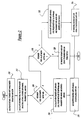
- a routine as in Figure 6 is used.
- desired airflow is adjusted based on a minimum allowable airflow, wherein the minimum allowable airflow is calculated recognising the minimum allowable fuel pulse width and effects from transient fuel phenomenon.
- step 610 the minimum fuel flow from the fuel injector (MIN_FUELFLOW_AT_MIN_PW in lbs/hr) at the minimum allowable fuel pulse width (MIN_PW in lbs/injection) is calculated based on engine speed (ENGINE_SPEED in revs/min), the number of cylinders (NUMBER_OF_CYLINDERS). Then, in step 612, the minimum fuel flow into the cylinders (MIN_FUELFLOW in lbs/hr), taking into account transient fuel (TRANS_FUEL in lbs/hr), is calculated by adding TRANS_FUEL and MIN_FUELFLOW_AT_MIN_PW.
- step 614 the minimum allowable airflow (MIN_AIRFLOW) to maintain a desired air-fuel ratio (DESIRED_A/F) is calculated based on MIN_FUELFLOW.
- step 616 the desired airflow (AM_DESIRED) is determined using various methods as described above herein with respect to Figure 2. For example, an idle speed controller, and engine torque controller, or various other controllers can be calculating a desired airflow for a variety of purposes.
- step 618 a determination is made as to whether desired airflow (AM_DESIRED) is less than minimum allowable airflow (MIN_AIRFLOW).
- AM_DESIRED desired airflow
- MIN_AIRFLOW minimum allowable airflow
- step 620 modified desired airflow (AM_REQUEST), which is used in Figure 4, is set equal to minimum allowable airflow (MIN_AIRFLOW).
- modified desired airflow (AM_REQUEST) can be adjusted based on signal EGO from sensor 16.
- modified desired airflow For example, if signal EGO indicates lean, modified desired airflow (AM_REQUEST) is decreased by a predetermined amount. If signal EGO indicates rich, modified desired airflow (AM_REQUEST) is increased by a predetermined amount. Otherwise, in step 622, modified desired airflow (AM_REQUEST) is set equal to desired airflow (AM_DESIRED).
- the invention can also be used with direct injection engines wherein fuel is injected directly into the engine cylinder. Also, the invention is applicable with various types of transient fuel algorithms, including those implemented in either the time domain or the event domain.
Landscapes
- Engineering & Computer Science (AREA)
- Chemical & Material Sciences (AREA)
- Combustion & Propulsion (AREA)
- Mechanical Engineering (AREA)
- General Engineering & Computer Science (AREA)
- Electrical Control Of Air Or Fuel Supplied To Internal-Combustion Engine (AREA)
Applications Claiming Priority (2)
| Application Number | Priority Date | Filing Date | Title |
|---|---|---|---|
| US481316 | 2000-01-11 | ||
| US09/481,316 US6273060B1 (en) | 2000-01-11 | 2000-01-11 | Method for improved air-fuel ratio control |
Publications (2)
| Publication Number | Publication Date |
|---|---|
| EP1116869A2 true EP1116869A2 (de) | 2001-07-18 |
| EP1116869A3 EP1116869A3 (de) | 2002-10-30 |
Family
ID=23911482
Family Applications (1)
| Application Number | Title | Priority Date | Filing Date |
|---|---|---|---|
| EP00311120A Withdrawn EP1116869A3 (de) | 2000-01-11 | 2000-12-13 | Steuerverfahren für das Luft-/Kraftstoffverhältnis |
Country Status (2)
| Country | Link |
|---|---|
| US (1) | US6273060B1 (de) |
| EP (1) | EP1116869A3 (de) |
Cited By (4)
| Publication number | Priority date | Publication date | Assignee | Title |
|---|---|---|---|---|
| CN102806915A (zh) * | 2011-05-31 | 2012-12-05 | 通用汽车环球科技运作有限责任公司 | 扭矩控制系统及方法 |
| WO2012164066A1 (en) | 2011-06-03 | 2012-12-06 | Caterpillar, Inc. | Cooler device |
| CN103161596A (zh) * | 2011-12-13 | 2013-06-19 | 福特环球技术公司 | 改进发动机启动的方法 |
| WO2021062334A1 (en) * | 2019-09-26 | 2021-04-01 | Setaysha Technical Solutions LLC | Air-fuel metering for internal combustion reciprocating engines |
Families Citing this family (36)
| Publication number | Priority date | Publication date | Assignee | Title |
|---|---|---|---|---|
| US7743606B2 (en) * | 2004-11-18 | 2010-06-29 | Honeywell International Inc. | Exhaust catalyst system |
| US7182075B2 (en) * | 2004-12-07 | 2007-02-27 | Honeywell International Inc. | EGR system |
| US7467614B2 (en) | 2004-12-29 | 2008-12-23 | Honeywell International Inc. | Pedal position and/or pedal change rate for use in control of an engine |
| US7165399B2 (en) * | 2004-12-29 | 2007-01-23 | Honeywell International Inc. | Method and system for using a measure of fueling rate in the air side control of an engine |
| US7275374B2 (en) * | 2004-12-29 | 2007-10-02 | Honeywell International Inc. | Coordinated multivariable control of fuel and air in engines |
| US7591135B2 (en) | 2004-12-29 | 2009-09-22 | Honeywell International Inc. | Method and system for using a measure of fueling rate in the air side control of an engine |
| US7328577B2 (en) | 2004-12-29 | 2008-02-12 | Honeywell International Inc. | Multivariable control for an engine |
| US20060168945A1 (en) * | 2005-02-02 | 2006-08-03 | Honeywell International Inc. | Aftertreatment for combustion engines |
| US7752840B2 (en) * | 2005-03-24 | 2010-07-13 | Honeywell International Inc. | Engine exhaust heat exchanger |
| US7469177B2 (en) * | 2005-06-17 | 2008-12-23 | Honeywell International Inc. | Distributed control architecture for powertrains |
| US7389773B2 (en) | 2005-08-18 | 2008-06-24 | Honeywell International Inc. | Emissions sensors for fuel control in engines |
| US7155334B1 (en) | 2005-09-29 | 2006-12-26 | Honeywell International Inc. | Use of sensors in a state observer for a diesel engine |
| US7765792B2 (en) * | 2005-10-21 | 2010-08-03 | Honeywell International Inc. | System for particulate matter sensor signal processing |
| US7357125B2 (en) * | 2005-10-26 | 2008-04-15 | Honeywell International Inc. | Exhaust gas recirculation system |
| US20070144149A1 (en) * | 2005-12-28 | 2007-06-28 | Honeywell International Inc. | Controlled regeneration system |
| US7415389B2 (en) * | 2005-12-29 | 2008-08-19 | Honeywell International Inc. | Calibration of engine control systems |
| JP4325701B2 (ja) * | 2007-05-16 | 2009-09-02 | トヨタ自動車株式会社 | 内燃機関の制御装置 |
| US7565899B2 (en) * | 2007-06-12 | 2009-07-28 | Ford Global Technologies, Llc | Engine fueling control during cylinder valve mode transitions |
| US8060290B2 (en) | 2008-07-17 | 2011-11-15 | Honeywell International Inc. | Configurable automotive controller |
| US8620461B2 (en) | 2009-09-24 | 2013-12-31 | Honeywell International, Inc. | Method and system for updating tuning parameters of a controller |
| US8504175B2 (en) | 2010-06-02 | 2013-08-06 | Honeywell International Inc. | Using model predictive control to optimize variable trajectories and system control |
| US9677493B2 (en) | 2011-09-19 | 2017-06-13 | Honeywell Spol, S.R.O. | Coordinated engine and emissions control system |
| US20130111905A1 (en) | 2011-11-04 | 2013-05-09 | Honeywell Spol. S.R.O. | Integrated optimization and control of an engine and aftertreatment system |
| US9650934B2 (en) | 2011-11-04 | 2017-05-16 | Honeywell spol.s.r.o. | Engine and aftertreatment optimization system |
| US9316172B2 (en) | 2013-04-05 | 2016-04-19 | Ford Global Technologies, Llc | Reducing enrichment due to minimum pulse width constraint |
| EP3051367B1 (de) | 2015-01-28 | 2020-11-25 | Honeywell spol s.r.o. | Ansatz und system zur handhabung von einschränkungen für gemessene störungen mit unsicherer vorschau |
| EP3056706A1 (de) | 2015-02-16 | 2016-08-17 | Honeywell International Inc. | Ansatz zur nachbehandlungssystemmodellierung und modellidentifizierung |
| EP3091212A1 (de) | 2015-05-06 | 2016-11-09 | Honeywell International Inc. | Identifikationsansatz für verbrennungsmotor-mittelwertmodelle |
| EP3125052B1 (de) | 2015-07-31 | 2020-09-02 | Garrett Transportation I Inc. | Quadratischer programmlöser für mpc mit variabler anordnung |
| US10272779B2 (en) | 2015-08-05 | 2019-04-30 | Garrett Transportation I Inc. | System and approach for dynamic vehicle speed optimization |
| US10415492B2 (en) | 2016-01-29 | 2019-09-17 | Garrett Transportation I Inc. | Engine system with inferential sensor |
| US10124750B2 (en) | 2016-04-26 | 2018-11-13 | Honeywell International Inc. | Vehicle security module system |
| US10036338B2 (en) | 2016-04-26 | 2018-07-31 | Honeywell International Inc. | Condition-based powertrain control system |
| EP3548729B1 (de) | 2016-11-29 | 2023-02-22 | Garrett Transportation I Inc. | Inferenzflusssensor |
| US11057213B2 (en) | 2017-10-13 | 2021-07-06 | Garrett Transportation I, Inc. | Authentication system for electronic control unit on a bus |
| JP7131479B2 (ja) * | 2019-05-21 | 2022-09-06 | トヨタ自動車株式会社 | ハイブリッド車両および、その制御方法 |
Citations (1)
| Publication number | Priority date | Publication date | Assignee | Title |
|---|---|---|---|---|
| US5746183A (en) | 1997-07-02 | 1998-05-05 | Ford Global Technologies, Inc. | Method and system for controlling fuel delivery during transient engine conditions |
Family Cites Families (18)
| Publication number | Priority date | Publication date | Assignee | Title |
|---|---|---|---|---|
| US4237830A (en) * | 1978-10-18 | 1980-12-09 | General Motors Corporation | Vehicle engine air and fuel mixture controller with engine overrun control |
| US4357923A (en) | 1979-09-27 | 1982-11-09 | Ford Motor Company | Fuel metering system for an internal combustion engine |
| JP2507315B2 (ja) * | 1986-03-26 | 1996-06-12 | 株式会社日立製作所 | 内燃機関制御装置 |
| US4903668A (en) | 1987-07-29 | 1990-02-27 | Toyota Jidosha Kabushiki Kaisha | Fuel injection system of an internal combustion engine |
| US4922877A (en) | 1988-06-03 | 1990-05-08 | Nissan Motor Company, Limited | System and method for controlling fuel injection quantity for internal combustion engine |
| DE3930396C2 (de) * | 1989-09-12 | 1993-11-04 | Bosch Gmbh Robert | Verfahren zum einstellen von luft- und kraftstoffmengen fuer eine mehrzylindrige brennkraftmaschine |
| JPH06323181A (ja) | 1993-05-14 | 1994-11-22 | Hitachi Ltd | 内燃機関の燃料制御方法及びその装置 |
| US5474052A (en) | 1993-12-27 | 1995-12-12 | Ford Motor Company | Automated method for cold transient fuel compensation calibration |
| JPH07259621A (ja) | 1994-03-18 | 1995-10-09 | Mitsubishi Motors Corp | 内燃機関用燃料供給制御装置 |
| US5492102A (en) * | 1994-05-04 | 1996-02-20 | Chrysler Corporation | Method of throttle fuel lean-out for internal combustion engines |
| US5469826A (en) * | 1994-05-04 | 1995-11-28 | Chrysler Corporation | Method of load and speed modifying on fuel lean-out for internal combustion engines |
| US5546910A (en) | 1995-07-06 | 1996-08-20 | Ford Motor Company | Air/fuel controller with compensation for secondary intake throttle transients |
| US5584277A (en) | 1995-09-26 | 1996-12-17 | Chrysler Corporation | Fuel delivery system with wall wetting history and transient control |
| JPH09250387A (ja) | 1996-03-19 | 1997-09-22 | Toyota Motor Corp | 内燃機関の燃料噴射制御方法 |
| US5765533A (en) | 1996-04-18 | 1998-06-16 | Nissan Motor Co., Ltd. | Engine air-fuel ratio controller |
| DE69821810T2 (de) * | 1997-03-17 | 2004-12-09 | Toyota Jidosha K.K., Toyota | Sperrsteuerungssystem für die Kraftstoffeinspritzung in einer Brennkraftmaschine |
| US5935188A (en) | 1997-05-27 | 1999-08-10 | Chrysler Corporation | Determination of wall wetting for a port injected engine |
| JP3913864B2 (ja) * | 1997-10-27 | 2007-05-09 | 三菱電機株式会社 | 内燃機関の筒内噴射式燃料制御装置 |
-
2000
- 2000-01-11 US US09/481,316 patent/US6273060B1/en not_active Expired - Lifetime
- 2000-12-13 EP EP00311120A patent/EP1116869A3/de not_active Withdrawn
Patent Citations (1)
| Publication number | Priority date | Publication date | Assignee | Title |
|---|---|---|---|---|
| US5746183A (en) | 1997-07-02 | 1998-05-05 | Ford Global Technologies, Inc. | Method and system for controlling fuel delivery during transient engine conditions |
Cited By (8)
| Publication number | Priority date | Publication date | Assignee | Title |
|---|---|---|---|---|
| CN102806915A (zh) * | 2011-05-31 | 2012-12-05 | 通用汽车环球科技运作有限责任公司 | 扭矩控制系统及方法 |
| CN102806915B (zh) * | 2011-05-31 | 2015-07-29 | 通用汽车环球科技运作有限责任公司 | 扭矩控制系统及方法 |
| WO2012164066A1 (en) | 2011-06-03 | 2012-12-06 | Caterpillar, Inc. | Cooler device |
| CN103161596A (zh) * | 2011-12-13 | 2013-06-19 | 福特环球技术公司 | 改进发动机启动的方法 |
| CN103161596B (zh) * | 2011-12-13 | 2016-12-21 | 福特环球技术公司 | 改进发动机启动的方法 |
| WO2021062334A1 (en) * | 2019-09-26 | 2021-04-01 | Setaysha Technical Solutions LLC | Air-fuel metering for internal combustion reciprocating engines |
| US11181052B2 (en) | 2019-09-26 | 2021-11-23 | Setaysha Technical Solutions, Llc | Air-fuel metering for internal combustion reciprocating engines |
| US12104544B2 (en) | 2019-09-26 | 2024-10-01 | Setaysha Technical Solutions LLC | Air-fuel metering for internal combustion reciprocating engines |
Also Published As
| Publication number | Publication date |
|---|---|
| US6273060B1 (en) | 2001-08-14 |
| EP1116869A3 (de) | 2002-10-30 |
Similar Documents
| Publication | Publication Date | Title |
|---|---|---|
| US6273060B1 (en) | Method for improved air-fuel ratio control | |
| JP3403728B2 (ja) | 空燃比制御方法 | |
| US7975670B2 (en) | Control unit and control method for torque-demand-type internal combustion engine | |
| US4389996A (en) | Method and apparatus for electronically controlling fuel injection | |
| US6155242A (en) | Air/fuel ratio control system and method | |
| EP2317106A1 (de) | Steuervorrichtung für einen verbrennungsmotor | |
| US7121233B2 (en) | Control apparatus for an internal combustion engine | |
| EP0964143B1 (de) | Vorrichting zur Steuerung der Moden einer Brennkraftmaschine mit Direkteinspritzung | |
| KR100237512B1 (ko) | 성층 연소 엔진의 연료분사 제어장치 | |
| US20090157270A1 (en) | Method for operating an internal combustion engine using externally supplied ignition | |
| JPS6166839A (ja) | 内燃機関の過回転防止燃料カツト制御装置 | |
| EP1306538A2 (de) | Vorrichtung und Verfahren zur Steuerung einer Brennkraftmaschine | |
| US6278933B1 (en) | Rapid transient torque management in DISI engines | |
| US5630394A (en) | Idle speed control | |
| US6305347B1 (en) | Monitor for lean capable engine | |
| EP1245810A2 (de) | Methode und System für das Steuern einer Maschine mit verbesserter Momentsteuerung | |
| US4523570A (en) | Fuel injection control in internal combustion engine | |
| KR20070108946A (ko) | 내연 엔진용 제어 장치 | |
| EP0909887A2 (de) | System zur Regelung der Leerlaufdrehzahl von fremdgezündeten Einspritz-Brennkraftmaschinen | |
| US7163002B1 (en) | Fuel injection system and method | |
| US6272850B1 (en) | Catalytic converter temperature control system and method | |
| US4915078A (en) | Fuel injection control device of an internal combustion engine | |
| US8161941B2 (en) | Control device for internal combustion engine | |
| US4502448A (en) | Method for controlling control systems for internal combustion engines immediately after termination of fuel cut | |
| EP4590946A1 (de) | Verfahren zur steuerung einer wasserstoff-brennkraftmaschine |
Legal Events
| Date | Code | Title | Description |
|---|---|---|---|
| PUAI | Public reference made under article 153(3) epc to a published international application that has entered the european phase |
Free format text: ORIGINAL CODE: 0009012 |
|
| AK | Designated contracting states |
Kind code of ref document: A2 Designated state(s): AT BE CH CY DE DK ES FI FR GB GR IE IT LI LU MC NL PT SE TR |
|
| AX | Request for extension of the european patent |
Free format text: AL;LT;LV;MK;RO;SI |
|
| PUAL | Search report despatched |
Free format text: ORIGINAL CODE: 0009013 |
|
| AK | Designated contracting states |
Kind code of ref document: A3 Designated state(s): AT BE CH CY DE DK ES FI FR GB GR IE IT LI LU MC NL PT SE TR |
|
| AX | Request for extension of the european patent |
Free format text: AL;LT;LV;MK;RO;SI |
|
| 17P | Request for examination filed |
Effective date: 20030326 |
|
| AKX | Designation fees paid |
Designated state(s): DE FR GB |
|
| STAA | Information on the status of an ep patent application or granted ep patent |
Free format text: STATUS: THE APPLICATION HAS BEEN WITHDRAWN |
|
| 18W | Application withdrawn |
Effective date: 20041111 |