EP1116883A2 - Compresseur à plateau en biais avec actionnement électrique - Google Patents
Compresseur à plateau en biais avec actionnement électrique Download PDFInfo
- Publication number
- EP1116883A2 EP1116883A2 EP00124523A EP00124523A EP1116883A2 EP 1116883 A2 EP1116883 A2 EP 1116883A2 EP 00124523 A EP00124523 A EP 00124523A EP 00124523 A EP00124523 A EP 00124523A EP 1116883 A2 EP1116883 A2 EP 1116883A2
- Authority
- EP
- European Patent Office
- Prior art keywords
- chamber
- refrigerant
- motor
- swash plate
- intermediate pressure
- Prior art date
- Legal status (The legal status is an assumption and is not a legal conclusion. Google has not performed a legal analysis and makes no representation as to the accuracy of the status listed.)
- Withdrawn
Links
- 239000003507 refrigerant Substances 0.000 claims abstract description 175
- 238000001816 cooling Methods 0.000 claims abstract description 10
- 238000011144 upstream manufacturing Methods 0.000 claims description 5
- 230000006835 compression Effects 0.000 abstract description 17
- 238000007906 compression Methods 0.000 abstract description 17
- 230000000694 effects Effects 0.000 abstract description 9
- 239000010687 lubricating oil Substances 0.000 abstract description 5
- 230000006866 deterioration Effects 0.000 abstract description 4
- CURLTUGMZLYLDI-UHFFFAOYSA-N Carbon dioxide Chemical compound O=C=O CURLTUGMZLYLDI-UHFFFAOYSA-N 0.000 description 6
- 230000006872 improvement Effects 0.000 description 4
- 229910002092 carbon dioxide Inorganic materials 0.000 description 3
- 239000001569 carbon dioxide Substances 0.000 description 3
- 230000007246 mechanism Effects 0.000 description 3
- 230000009467 reduction Effects 0.000 description 3
- QGZKDVFQNNGYKY-UHFFFAOYSA-N Ammonia Chemical compound N QGZKDVFQNNGYKY-UHFFFAOYSA-N 0.000 description 2
- 230000007423 decrease Effects 0.000 description 2
- 238000006073 displacement reaction Methods 0.000 description 2
- 238000000034 method Methods 0.000 description 2
- 230000008569 process Effects 0.000 description 2
- 230000000630 rising effect Effects 0.000 description 2
- 230000009471 action Effects 0.000 description 1
- 229910021529 ammonia Inorganic materials 0.000 description 1
- 230000008859 change Effects 0.000 description 1
- 230000003247 decreasing effect Effects 0.000 description 1
- 238000007599 discharging Methods 0.000 description 1
- 239000003595 mist Substances 0.000 description 1
- 238000013021 overheating Methods 0.000 description 1
- 230000002787 reinforcement Effects 0.000 description 1
- 238000003756 stirring Methods 0.000 description 1
Images




Classifications
-
- F—MECHANICAL ENGINEERING; LIGHTING; HEATING; WEAPONS; BLASTING
- F04—POSITIVE - DISPLACEMENT MACHINES FOR LIQUIDS; PUMPS FOR LIQUIDS OR ELASTIC FLUIDS
- F04B—POSITIVE-DISPLACEMENT MACHINES FOR LIQUIDS; PUMPS
- F04B39/00—Component parts, details, or accessories, of pumps or pumping systems specially adapted for elastic fluids, not otherwise provided for in, or of interest apart from, groups F04B25/00 - F04B37/00
- F04B39/06—Cooling; Heating; Prevention of freezing
- F04B39/064—Cooling by a cooling jacket in the pump casing
-
- F—MECHANICAL ENGINEERING; LIGHTING; HEATING; WEAPONS; BLASTING
- F04—POSITIVE - DISPLACEMENT MACHINES FOR LIQUIDS; PUMPS FOR LIQUIDS OR ELASTIC FLUIDS
- F04B—POSITIVE-DISPLACEMENT MACHINES FOR LIQUIDS; PUMPS
- F04B27/00—Multi-cylinder pumps specially adapted for elastic fluids and characterised by number or arrangement of cylinders
- F04B27/08—Multi-cylinder pumps specially adapted for elastic fluids and characterised by number or arrangement of cylinders having cylinders coaxial with, or parallel or inclined to, main shaft axis
- F04B27/0873—Component parts, e.g. sealings; Manufacturing or assembly thereof
- F04B27/0895—Component parts, e.g. sealings; Manufacturing or assembly thereof driving means
-
- F—MECHANICAL ENGINEERING; LIGHTING; HEATING; WEAPONS; BLASTING
- F04—POSITIVE - DISPLACEMENT MACHINES FOR LIQUIDS; PUMPS FOR LIQUIDS OR ELASTIC FLUIDS
- F04B—POSITIVE-DISPLACEMENT MACHINES FOR LIQUIDS; PUMPS
- F04B27/00—Multi-cylinder pumps specially adapted for elastic fluids and characterised by number or arrangement of cylinders
- F04B27/08—Multi-cylinder pumps specially adapted for elastic fluids and characterised by number or arrangement of cylinders having cylinders coaxial with, or parallel or inclined to, main shaft axis
- F04B27/10—Multi-cylinder pumps specially adapted for elastic fluids and characterised by number or arrangement of cylinders having cylinders coaxial with, or parallel or inclined to, main shaft axis having stationary cylinders
- F04B27/1036—Component parts, details, e.g. sealings, lubrication
-
- F—MECHANICAL ENGINEERING; LIGHTING; HEATING; WEAPONS; BLASTING
- F04—POSITIVE - DISPLACEMENT MACHINES FOR LIQUIDS; PUMPS FOR LIQUIDS OR ELASTIC FLUIDS
- F04B—POSITIVE-DISPLACEMENT MACHINES FOR LIQUIDS; PUMPS
- F04B35/00—Piston pumps specially adapted for elastic fluids and characterised by the driving means to their working members, or by combination with, or adaptation to, specific driving engines or motors, not otherwise provided for
- F04B35/04—Piston pumps specially adapted for elastic fluids and characterised by the driving means to their working members, or by combination with, or adaptation to, specific driving engines or motors, not otherwise provided for the means being electric
Definitions
- the present invention relates to an electric type swash plate compressor for use in a vehicle air conditioner and the like.
- An electric compressor is known as a compressor included in a refrigerant circulation circuit of a heat exchanger such as the vehicle air conditioner.
- the electric compressor has an electric motor and a compression mechanism to compress refrigerant driven by the motor within an outer casing of the compressor.
- the compression mechanism is composed of pistons accommodated so as to reciprocate in cylinder bores in the compressor, and of a swash plate, which is located in a crank chamber defined in the compressor and converts rotating movement of the motor to reciprocating movement of the pistons.
- the motor capacity to rotate at a high speed and a driving force to endure a high load torque are expected. So, the compressor needs to have a powerful motor.
- Japanese Unexamined Patent Publication No. 7-133779 is known.
- the discharged refrigerant from the compression mechanism which is sent to the device downstream to the compressor, such as a condenser, is introduced into a motor chamber, and is used to cool down the motor.
- Japanese Unexamined Patent Publication No. 9-236092 discloses the following arrangement.
- the discharged refrigerant in high pressure prevents the casing from making it compact and reducing its weight. That is, the motor chamber occupies a large space in the compressor, and it needs to improve the strength of the casing, such as an increase of the thickness of the casing, an increase of reinforcement and the thickness inside the casing, so that the casing can resist high pressure.
- the refrigerant used to cool down the motor in itself is high in temperature, so the motor is not efficiently cooled down.
- the object of the present invention is to offer an electric type swash plate compressor which can be not only compact and reduced in weight but also efficiently cool down a motor chamber and a crank chamber.
- the compressor has a motor chamber, a crank chamber and cylinder bores formed within an outer casing, and pistons accommodated in the cylinder bores so as to be reciprocated, and a drive shaft extended in the motor chamber and the crank chamber so as to be rotatably supported in the casing, connected to an electric motor in the motor chamber and reciprocating the pistons through the swash plate connected to the drive shaft in the crank chamber.
- a communication route which introduces a refrigerant in lower temperature than a refrigerant in a discharge chamber into the motor chamber formed in an inner refrigerant circuit in the casing passes through the crank chamber.
- the motor chamber and the crank chamber of the electric type swash plate compressor are cooled down when the refrigerant in the inner refrigerant circuit in the casing is introduced through the communication route.
- the refrigerant introduced into both chambers is lower in temperature and in pressure than the refrigerant in the discharge chamber communicating with the external refrigerant circuit, or the discharge refrigerant. So, it can reduce temperature and pressure more in both chambers than the arrangement that the discharge refrigerant is used to cool down the chambers. That is, the cooling efficiency can be improved and moreover, the pressure resisting strength of the casing can be reduced.
- the compressor is a multistage type having a first cylinder bore, where the refrigerant drawn from the external refrigerant circuit is compressed, and a second cylinder bore, where the refrigerant in intermediate pressure, at least once being compressed, is drawn and compressed.
- the communication route communicates an intermediate pressure chamber having the refrigerant in intermediate pressure with the motor chamber.
- the motor chamber and the crank chamber are cooled down by the refrigerant in the intermediate pressure discharged into the intermediate pressure chamber of the multistage compressor. Since the refrigerant in the intermediate pressure is much lower in temperature and in pressure than the discharge refrigerant, it is suitable for the improvement of the cooling efficiency and the reduction of the pressure resisting strength of the casing.
- the motor chamber is arranged upstream to the crank chamber in the communication route, and at least a part of the refrigerant is introduced into the crank chamber through the motor chamber.
- the motor chamber before the crank chamber is cooled down, the motor chamber is cooled down. That is, the refrigerant in low temperature of which temperature does not rise in the crank chamber at least cools down the motor chamber, so the cooling efficiency of the motor chamber is further improved.
- the communication route communicates either of the suction chamber having the refrigerant drawn from the external refrigerant circuit and the intake port introducing the refrigerant into the suction chamber with the motor chamber.
- the refrigerant drawn from the external refrigerant circuit is introduced into the motor chamber and the crank chamber.
- the refrigerant is still lower in temperature and in pressure than the refrigerant in intermediate pressure. Accordingly, the present invention is further suitable for the improvement of the cooling efficiency and the reduction of the pressure resisting strength of the casing.
- the branch communicating passage which is branched from the suction chamber or the intake port, constitutes the inner refrigerant circuit in the casing of the compressor and is arranged upstream to the motor chamber and the crank chamber.
- the suction refrigerant is introduced into the motor chamber and the crank chamber through the branch communicating passage. At that time some part of the suction refrigerant is introduced into both chambers, while the other part of the refrigerant is not introduced into both chambers but is drawn into the cylinder bores. Accordingly, the suction refrigerant, of which temperature highly rises in both chambers, occupies only a part of the refrigerant, so the refrigerant drawn into the cylinder bores does not rise in temperature relatively. That is, the fall of the compressive efficiency, which is caused by the increase of the specific volume by a rise of the refrigerant in temperature drawn into the cylinder bores, can be prevented.
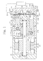
- FIG. 1 A first embodiment of a multistage electric type swash plate compressor which uses carbon dioxide as a refrigerant according to the present invention will now be described in Fig. 1 and Fig. 2.
- the left side of Fig. 1 is the front of the compressor, and the right side of Fig. 1 is the rear of it.
- the electric type swash plate compressor has a motor housing 11, a front housing 12, a cylinder block 13 and a rear housing 14.
- Each of the housings 11, 12 and 14, and the cylinder block 13 are secured each other with through bolts which are not illustrated, and constitute an outer casing of the compressor almost in a cylindrical shape.
- a motor chamber 15 is defined in a region surrounded by the motor housing 11 and the front housing 12.
- a crank chamber 16 is defined in a region surrounded by the front housing 12 and the cylinder block 13.
- a drive shaft 17 which is inserted into the motor chamber 15 and the crank chamber 16, is rotatably supported through front and rear radial bearings 18A and 18B, between the motor housing 11 and the cylinder block 13.
- the drive shaft 17 is loosely inserted into a central bore 12B of a front wall 12A formed in the front housing 12.
- an electric motor 21 composed of a stator 19 and a rotor 20, is accommodated.
- the rotor 20 is integrally and rotatably fixed on the drive shaft 17.
- a swash plate 22 in a disk shape is integrally and rotatably fixed on the drive shaft 17, and a thrust bearing 23 is mounted between the swash plate 22 and the front wall 12A.
- the drive shaft 17 and the swash plate 22 is positioned in the thrust direction (in the direction of axis of the drive shaft) by the thrust bearing 23 and a washer 25, which is urged forward by a spring 24 placed in a recess formed in the center of the cylinder block 13.
- first cylinder bore 13A and the second cylinder bore 13B which is another cylinder bore having smaller radius than the cylinder bore 13A, are formed in an opposite position with respect to the drive shaft 17 each other.
- a single head type first piston 26 and second piston 27 are respectively accommodated so as to reciprocate back and forth slidably in each of the cylinder bores 13A and 13B.
- Compression chambers 13E and 13F which change each volume in accordance with reciprocating movement of each pistons 26 and 27 are respectively defined in each cylinder bores 13A and 13B.
- concave portions 26A and 27A are respectively formed, and pair of shoes 28 and 29 are respectively accommodated therein.
- Circumferetial portion of the swash plate 22 is slidably sandwiched by shoes 28 and 29, so each of the pistons 26 and 27 is operably connected to the swash plate 22. Therefore, the rotational movement of the swash plate 22 is converted into liner reciprocating movements of the pistons 26 and 27 with the strokes in accordance with the inclination angle of the swash plate 22 when the swash plate 22 rotates synchronously with the drive shaft 17, which is rotated by the electric motor 21.
- a valve plate assembly 30 is sandwiched between the cylinder block 13 and the rear housing 14. As shown in Figs. 1 and 2, a suction chamber 31, where the refrigerant drawn from the external refrigerant circuit 50 is introduced through the intake port 31A formed in the circumferential wall of the rear housing 14, is formed between the valve plate assembly 30 and the rear housing 14.
- An intermediate pressure chamber 32 connecting the cylinder bore 13A to the cylinder bore 13B, and the discharge chamber 33 communicating with the external refrigerant circuit 50 through the outlet port 33A formed in the rear wall of the rear housing 14, are defined.
- the valve plate assembly 30 comprises a suction valve disk 34, a valve plate 35, first and second discharge valves 36A and 36B, first and second retainers 37A and 37B, pins 30A and 30C.
- ports 35A, 35B, 35C, 35D and 35E are formed in the valve plate 35.
- the port 35A communicates the suction chamber 31 with the first cylinder bore 13A
- the port 35B communicates the first cylinder bore 13A with the intermediate pressure chamber 32.
- the port 35C communicates the second cylinder bore 13B with the intermediate pressure chamber 32
- the port 35D communicates the second cylinder bore 13B with the discharge chamber 33.
- the port 35E communicates the intermediate pressure chamber 32 with the crank chamber 16 through a communication passage 38 as mentioned later.
- suction valves are formed in position corresponding to the ports 35A and 35C.
- the discharge valve 36A and the retainer 37A are fixed to the suction valve disk 34 and the valve plate 35 by the pin 30A in the intermediate pressure chamber 32.
- the discharge valve 36B and the retainer 37B are fixed to both the suction valve disk 34 and the valve plate 35 by the pin 30C.
- An inner refrigerant circuit in the compressor comprises the intake port 31A, the suction chamber 31, the port 35A, the first cylinder bore 13A, the port 35B, the intermediate pressure chamber 32, the port 35C, the second cylinder bore 13B, the port 35D, the discharge chamber 33 and the outlet port 33A.
- the communication passage 38 communicating the intermediate pressure chamber 32 with the crank chamber 16 is formed in the cylinder block 13.
- the communication bore 12C communicating the crank chamber 16 with the motor chamber 15 is formed in the front wall 12A of the front housing 12.
- the communication passage 38, the crank chamber 16, the central bore 12B of the front housing 12 and the communication bore 12C constitute a communication route communicating the intermediate pressure chamber 32 with the motor chamber 15.
- the refrigerant drawn from the intake port 31A to the suction chamber 31 is drawn into the compression chamber 13E through the port 35A, and the refrigerant is compressed by the rearward movement of the piston 26. Then the refrigerant is discharged into the intermediate pressure chamber 32 through the port 35B.
- a part of the refrigerant in the intermediate pressure chamber 32 is drawn into the compression chamber 13F through the port 35C, and the refrigerant is compressed by the second piston 27. Then the refrigerant is discharged into the discharge chamber 33 through the port 35D. The refrigerant discharged into the discharge chamber 33 is sent out to the external refrigerant circuit 50 through the outlet port 33A.
- the refrigerant in the intermediate pressure chamber 32 which is not drawn into the compression chamber 13F, is supplied into the crank chamber 16 through the port 35E and the communication passage 38. Then the refrigerant is supplied into the motor chamber 15 from the crank chamber 16 through the thrust bearing 23, the central bore 12B of the front housing 12 and the communication bore 12C.
- the refrigerant is effectively supplied into the motor chamber 15 or the crank chamber 16 by stir of rotation of the rotor 20 and the swash plate 22 by rotation of the electric motor 21. Therefore, the electric motor 21 is cooled down by the refrigerant supplied into the motor chamber 15, and the swash plate 22, the shoes 28, 29 and the like are cooled down by the refrigerant supplied into the crank chamber 16.
- the refrigerant in the intermediate pressure chamber 32 is much lower in temperature and in pressure than the refrigerant in the discharge chamber 33 compressed in both the compression chambers 13E and 13F, since the refrigerant in the intermediate pressure chamber 32 is compressed only in the compression chamber 13E.
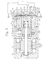
- the electric type swash plate compressor according to the embodiment is shown in Figs. 3 and 4.
- the arrangements of the refrigerant circuit and the communication route inside the casing according to the first embodiment are changed.
- the embodiment is the same arrangement as the electric type swash plate compressor according to the first embodiment. Accordingly, the same reference numerals as the first embodiment are given to the components which are common to the first embodiment, and the overlapped description is omitted.
- the suction chamber 31, the discharge chamber 33, and two intermediate pressure chambers 32A and 32B are defined between the valve plate assembly 30 and the rear housing 14.
- the first intermediate pressure chamber 32A communicates with the port 35B and a hole 30B
- the second intermediate pressure chamber 32B communicates with the ports 35C and 35E.
- a hole 30B is formed so as to penetrate a pin 30A in the direction of the axis.
- a central bore 13C of the cylinder block 13 is formed so as to communicate the hole 30B and a recessed portion of the central bore 13C which accommodates the rear end of the drive shaft 17.
- a communication passage 17A in a drive shaft 17 is formed so that the front area in the motor chamber 15 communicates with the central bore 13C of the cylinder block 13.
- the communication passage 38 is formed so that the crank chamber 16 always communicates with the port 35E.
- a communication route is comprised of the hole 30B, the central bore 13C, the communication passage 17A, the central bore 12B, the communication bore 12C, the communication passage 38, the port 35E and the crank chamber 16 so that the intermediate pressure chambers 32A and 32B always communicate with each other through the motor chamber 15.
- the intake port 31A, the suction chamber 31, the port 35A, the first cylinder bore 13A, the port 35B, the first and the second intermediate pressure chambers 32A and 32B, the port 35C, the second cylinder bore 13B, the port 35D, the discharge chamber 33 and the outlet port 33A constitute the inner refrigerant circuit inside of the casing.
- the refrigerant which is drawn from the suction chamber 31 to the first cylinder bore 13A and compressed, is discharged through the port 35B into the first intermediate pressure chamber 32A.
- the refrigerant in the first intermediate pressure chamber 32A is introduced into the front area in the motor chamber 15 through the hole 30B, the central bore 13C and the communication passage 17A.
- the refrigerant introduced into the motor chamber 15 passes a space between the stator 19 and the rotor 20, and is introduced into the crank chamber 16 through the communication bore 12C, the central bore 12B and the thrust bearing 23. Then the refrigerant in the crank chamber 16 is introduced into the second intermediate pressure chamber 32B through the communication passage 38.
- the refrigerant in the second intermediate pressure chamber 32B is drawn into the second cylinder bore 13B through the port 35C, and is further compressed by the second piston 27, and is discharged into the external refrigerant circuit through the port 35D, the discharge chamber 33 and the outlet port 33A.
- the electric type swash plate compressor according to the embodiment is shown in Figs. 5 and 6.
- the arrangements of the refrigerant circuit and the communication route inside of the casing according to the second embodiment are changed.
- the compressor is the same arrangement as the electric type swash plate compressor according to the second embodiment. Accordingly, the same reference numerals as the second embodiment are given to the components which are common to the second embodiment, and the overlapped description is omitted.
- the second intermediate pressure chamber 32B is formed so as to extend near the outer circumferential portion of the rear housing 14.
- a communication passage 40 as a means for cooling down the refrigerant, is formed in a convex portion 39 which is protruded parallel to the drive shaft 17, at the outer circumferential surface of the casing of the compressor (the rear housing 14 in Fig. 6).
- the motor chamber 15 and the intermediate pressure chamber 32B communicate with each other through the communication passage 40 and the port 35F.
- the communication passage 40 is penetrated across the motor housing 11, the front housing 12 and cylinder block 13, and always communicates between the port 35F and the front area of the motor chamber 15.
- the intake port 31A, the suction chamber 31, the port 35A, the first cylinder bore 13A, the port 35B, the first and the second intermediate pressure chambers 32A and 32B, the port 35C, the second cylinder bore 13B, the port 35D, the discharge chamber 33 and the outlet port 33A constitute the refrigerant circuit inside of the casing.
- the refrigerant in the first intermediate pressure chamber 32A is introduced into the crank chamber 16 through the hole 30B and the communication bore 13D of a cylinder block 13.
- the refrigerant in the crank chamber 16 is introduced into the rear area of the motor chamber 15 through the communication bore 12C and the central bore 12B of the front housing 12, and the thrust bearing 23.
- the refrigerant introduced into the motor chamber 15 passes the space between the stator 19 and the rotor 20.
- the refrigerant is introduced into the opening of the communication passage 40 formed in the front area of the motor chamber 15, and is introduced into the second intermediate pressure chamber 32B through the communication passage 40 and the port 35F.
- the refrigerant in the second intermediate pressure chamber 32B is drawn into the compression chamber 13F through the port 35C, and is further compressed by the second piston 27. Finally, the refrigerant is sent out to the external refrigerant circuit through the port 35D, the discharge chamber 33 and the outlet port 33A.
- the fourth embodiment will be explained with reference to Figs. 7 to 8.
- the arrangements of the refrigerant circuit and the communication route inside of the casing according to the first embodiment are changed.
- the arrangement of the embodiment is the same as the arrangement of the first embodiment. Accordingly, the same reference numerals as the first embodiment are given to the components which are common to the first embodiment, and the overlapped description is omitted.
- the ports 35A, 35B, 35C, 35D and 35G are formed in the valve plate 35.
- a communication passage 41 is formed to penetrate the cylinder block 13 to communicate with the port 35G.
- the communication passage 41 and the port 35G always communicate the suction chamber 31 with the crank chamber 16.
- the front area in the motor chamber 15 always communicates with the intake port 31A through a branch communicating passage 42 branched from the intake port 31A.
- the branch communicating passage 42 is penetrated between the motor chamber 15 and the intake port 31A across the motor housing 11, the front housing 12, the cylinder block 13 and the rear housing 14.
- the branch communicating passage 42, the bores 12B and 12C, the crank chamber 16, the communication route 41 and the port 35G constitute the communication route which always communicates the intake port 31A with the suction chamber 31 through the motor chamber 15.
- a part of the refrigerant circuit inside of the casing is constituted by this communication route and the motor chamber 15.
- a part of the refrigerant drawn through the intake port 31A from the external refrigerant circuit 50 is directly drawn into the suction chamber 31 through the intake port 31A.
- the other refrigerant is introduced into the front area of the motor chamber 15 through the branch communicating passage 42.
- the refrigerant introduced into the motor chamber 15 passes through the space between the stator 19 and the rotor 20, and introduced into the crank chamber 16 through the communication bore 12C, the central bore 12B and the thrust bearing 23. Then the refrigerant in the crank chamber 16 is introduced into the suction chamber 31 through the communication passage 41.
- the fifth embodiment will be explained with reference to Fig. 9.
- the branch communicating passage 42 is not formed but the intake port 31A is formed in the motor housing 11 so as to communicate the external refrigerant circuit with the front area of the motor chamber 15. Accordingly, the same reference numerals as the fourth embodiment are given to the components which are common to the fourth embodiment, and the overlapped description is omitted.
- the central bore 12B, the communication bore 12C, the crank chamber 16, the communication passage 41 and the port 35G constitute the communication route which communicates the intake port 31A with the suction chamber 31.
- the intake port 31A, the suction chamber 31, the port 35A, the first cylinder bore 13A, the port 35B, the intermediate pressure chamber 32, the port 35C, the second cylinder bore 13B, the port 35D, the discharge chamber 33 and the outlet port 33A constitute the refrigerant circuit inside of the casing.
- the refrigerant drawn into the intake port 31A from the external refrigerant circuit 50 is introduced into the front area of the motor chamber 15.
- the refrigerant introduced into the motor chamber 15 passes through the space between the stator 19 and the rotor 20, and is introduced into the crank chamber 16 through the communication bore 12C, the central bore 12B and the thrust bearing 23. Then, the refrigerant in the crank chamber 16 is introduced into the suction chamber 31 through the communication passage 41.
- the intake port 31A is formed in the motor housing 11.
- the refrigerant introduced from the external refrigerant circuit 50 is introduced into the crank chamber 16 after the motor chamber 15. That is, the refrigerant is directly introduced into the motor chamber 15 from the external refrigerant circuit 50 through a very short route before introduced into the crank chamber 16. Accordingly, the motor chamber 15 is efficiently cooled down by the refrigerant in low temperature, which hardly has risen in temperature before introduced into the motor chamber 15.
- a swash plate is inclinably arranged, and the discharge capacity is adjusted by controlling the pressure in the crank chamber by opening and closing a control valve arranged in the passage which communicates the suction chamber with the crank chamber.
- the arrangements of the fourth embodiment and the fifth embodiment may be applied to the single stage compressor.
- refrigerants such as ammonia can be used instead of carbon dioxide.
- the object of the present invention is to offer an electric type swash plate compressor which is compact and reduced in weight and lightened, and which can efficiently cool down a motor chamber and a crank chamber.
- the compressor has an electric motor and a swash plate, which are respectively accommodated in the motor chamber and the crank chamber.
- a communication route which communicates a part except the discharge chamber communicating with an external refrigerant circuit in an inner refrigerant circuit within an outer casing with the motor chamber, is formed.
- the communication route is formed so as to pass through the crank chamber, and the refrigerant in lower temperature and lower pressure than discharge refrigerant is supplied into the motor chamber and the crank chamber. Accordingly, the improvement of cooling efficiency and the reduction of pressure resisting strength of the casing can be performed.
Landscapes
- Engineering & Computer Science (AREA)
- Mechanical Engineering (AREA)
- General Engineering & Computer Science (AREA)
- Manufacturing & Machinery (AREA)
- Compressors, Vaccum Pumps And Other Relevant Systems (AREA)
- Compressor (AREA)
Applications Claiming Priority (2)
| Application Number | Priority Date | Filing Date | Title |
|---|---|---|---|
| JP2000002969 | 2000-01-11 | ||
| JP2000002969A JP2001193639A (ja) | 2000-01-11 | 2000-01-11 | 電動斜板圧縮機 |
Publications (2)
| Publication Number | Publication Date |
|---|---|
| EP1116883A2 true EP1116883A2 (fr) | 2001-07-18 |
| EP1116883A3 EP1116883A3 (fr) | 2002-10-23 |
Family
ID=18531997
Family Applications (1)
| Application Number | Title | Priority Date | Filing Date |
|---|---|---|---|
| EP00124523A Withdrawn EP1116883A3 (fr) | 2000-01-11 | 2000-11-09 | Compresseur à plateau en biais avec actionnement électrique |
Country Status (3)
| Country | Link |
|---|---|
| US (1) | US6565329B2 (fr) |
| EP (1) | EP1116883A3 (fr) |
| JP (1) | JP2001193639A (fr) |
Cited By (4)
| Publication number | Priority date | Publication date | Assignee | Title |
|---|---|---|---|---|
| WO2004094827A1 (fr) * | 2003-04-23 | 2004-11-04 | Halla Climate Control Corporation | Motocompresseur |
| EP1806503A1 (fr) * | 2006-01-10 | 2007-07-11 | Anest Iwata Corporation | Compresseur à gaz de type survolteur |
| WO2009143916A1 (fr) * | 2008-05-30 | 2009-12-03 | Wabco Gmbh | Dispositif pour faire fonctionner un groupe auxiliaire d’un véhicule à moteur, en particulier d’un véhicule utilitaire |
| EP2075471A3 (fr) * | 2007-12-25 | 2014-04-30 | Calsonic Kansei Corporation | Compresseur électrique |
Families Citing this family (27)
| Publication number | Priority date | Publication date | Assignee | Title |
|---|---|---|---|---|
| JP4066633B2 (ja) * | 2001-10-09 | 2008-03-26 | 株式会社豊田自動織機 | 流体加圧ポンプおよび流体タンクユニット |
| US7200024B2 (en) * | 2002-08-02 | 2007-04-03 | Micron Technology, Inc. | System and method for optically interconnecting memory devices |
| US7254331B2 (en) * | 2002-08-09 | 2007-08-07 | Micron Technology, Inc. | System and method for multiple bit optical data transmission in memory systems |
| JP2004183605A (ja) | 2002-12-05 | 2004-07-02 | Sanden Corp | 電動圧縮機 |
| WO2004094825A1 (fr) * | 2003-04-23 | 2004-11-04 | Halla Climate Control Corporation | Compresseur de type a plateau oscillant electromoteur |
| KR100922427B1 (ko) * | 2003-04-23 | 2009-10-16 | 한라공조주식회사 | 전동 사판식 압축기 |
| KR100941707B1 (ko) | 2003-09-29 | 2010-02-12 | 한라공조주식회사 | 전동 압축기 |
| US20050050237A1 (en) * | 2003-08-28 | 2005-03-03 | Jeddeloh Joseph M. | Memory module and method having on-board data search capabilities and processor-based system using such memory modules |
| KR100941708B1 (ko) | 2003-09-29 | 2010-02-11 | 한라공조주식회사 | 전동 압축기 |
| US20050089417A1 (en) * | 2003-10-27 | 2005-04-28 | Thar Technologies, Inc. | Positive displacement pump |
| US7188219B2 (en) * | 2004-01-30 | 2007-03-06 | Micron Technology, Inc. | Buffer control system and method for a memory system having outstanding read and write request buffers |
| US7412574B2 (en) * | 2004-02-05 | 2008-08-12 | Micron Technology, Inc. | System and method for arbitration of memory responses in a hub-based memory system |
| US7181584B2 (en) * | 2004-02-05 | 2007-02-20 | Micron Technology, Inc. | Dynamic command and/or address mirroring system and method for memory modules |
| US7590797B2 (en) * | 2004-04-08 | 2009-09-15 | Micron Technology, Inc. | System and method for optimizing interconnections of components in a multichip memory module |
| US7363419B2 (en) * | 2004-05-28 | 2008-04-22 | Micron Technology, Inc. | Method and system for terminating write commands in a hub-based memory system |
| AT501235B1 (de) * | 2004-11-23 | 2006-12-15 | Hoerbiger Automatisierungstech | Hydraulisches kombinationsaggregat |
| DE102006058355A1 (de) * | 2006-03-10 | 2007-09-13 | Brueninghaus Hydromatik Gmbh | Kombi-Pumpengehäuse für mehrere Nenngrößen |
| KR101104283B1 (ko) * | 2006-05-03 | 2012-01-11 | 한라공조주식회사 | 압축기 |
| US20080107547A1 (en) * | 2006-10-19 | 2008-05-08 | General Electric | Systems for cooling motors for gas compression applications |
| JP4833237B2 (ja) * | 2008-03-03 | 2011-12-07 | 川崎重工業株式会社 | 電動機一体型油圧モータ |
| JP5299342B2 (ja) * | 2010-03-31 | 2013-09-25 | 株式会社豊田自動織機 | 電動圧縮機 |
| CN102705191B (zh) * | 2012-06-01 | 2015-09-23 | 沈如华 | 调色机的色浆定量供应装置 |
| GB201608449D0 (en) * | 2016-05-13 | 2016-06-29 | Rolls Royce Controls & Data Services Ltd | Axial piston pump |
| KR102730508B1 (ko) * | 2019-08-22 | 2024-11-13 | 현대자동차주식회사 | 다단 압축 장치 및 그의 제어방법 |
| EP3929436B1 (fr) * | 2020-06-24 | 2024-02-21 | BITZER Kühlmaschinenbau GmbH | Compresseur de réfrigérant |
| US11760228B2 (en) * | 2021-05-11 | 2023-09-19 | Hyundai Motor Company | Electric power and thermal management system |
| KR20220153400A (ko) | 2021-05-11 | 2022-11-18 | 현대자동차주식회사 | 프로펠러용 구동기를 이용한 오일 분산 시스템 |
Citations (2)
| Publication number | Priority date | Publication date | Assignee | Title |
|---|---|---|---|---|
| JPH07133779A (ja) | 1993-11-08 | 1995-05-23 | Sanyo Electric Co Ltd | 内部高圧式圧縮機 |
| JPH09236092A (ja) | 1996-02-27 | 1997-09-09 | Mitsubishi Heavy Ind Ltd | 冷凍装置用密閉型圧縮機 |
Family Cites Families (18)
| Publication number | Priority date | Publication date | Assignee | Title |
|---|---|---|---|---|
| US3295457A (en) * | 1964-03-06 | 1967-01-03 | Oram Harold George | Fluid pressure developing units |
| US3934967A (en) * | 1973-07-12 | 1976-01-27 | Sundstrand Corporation | Refrigeration compressor and system |
| FR2410750A1 (fr) * | 1977-11-30 | 1979-06-29 | Girodin Marius | Compresseur multietage en barillet |
| US4388808A (en) * | 1982-02-17 | 1983-06-21 | The United States Of America As Represented By The Secretary Of The Army | Swash plate driving means for cryogenic coolers |
| US4743176A (en) * | 1986-06-18 | 1988-05-10 | Tecumseh Products Company | Gas flow system for a compressor |
| US4850812A (en) * | 1987-09-18 | 1989-07-25 | Versatron Corporation | Integrated motor pump combination |
| JPH01167474A (ja) * | 1987-12-24 | 1989-07-03 | Mayekawa Mfg Co Ltd | 密封型電動圧縮装置の冷却方法 |
| US4850816A (en) * | 1988-06-30 | 1989-07-25 | Bristol Compressors, Inc. | Refrigerant gas compressor unit |
| US4995791A (en) * | 1988-11-25 | 1991-02-26 | Bristol Compressors, Inc. | Refrigerant gas compressor unit |
| JP3298126B2 (ja) | 1992-01-14 | 2002-07-02 | 株式会社日立製作所 | 冷媒圧縮機 |
| JPH05256285A (ja) | 1992-03-13 | 1993-10-05 | Toshiba Corp | 極低温冷凍機用二段圧縮コンプレッサ |
| KR100202786B1 (ko) * | 1994-04-07 | 1999-06-15 | 이소가이 지세이 | 클러치레스 압축기의 방열구조체 |
| DE4423023C2 (de) * | 1994-06-30 | 1998-07-09 | Brueninghaus Hydromatik Gmbh | Axialkolbenmaschine mit einem Kühlkreislauf für die Zylinder und Kolben |
| JP3584999B2 (ja) * | 1995-03-06 | 2004-11-04 | 株式会社小松製作所 | 電気油圧ハイブリッドモータとその制御装置およびその制御方法 |
| JPH0932729A (ja) * | 1995-07-19 | 1997-02-04 | Mitsubishi Heavy Ind Ltd | 電動圧縮機 |
| TW347464B (en) * | 1996-11-15 | 1998-12-11 | Sanyo Electric Co | Stirling cycle machine |
| US6280151B1 (en) | 1998-03-09 | 2001-08-28 | Kabushiki Kaisha Toyoda Jidoshokki Seisakusho | Single-ended swash plate compressor |
| JP2000054956A (ja) * | 1998-08-07 | 2000-02-22 | Toyota Autom Loom Works Ltd | ハイブリッドコンプレッサ |
-
2000
- 2000-01-11 JP JP2000002969A patent/JP2001193639A/ja active Pending
- 2000-11-09 EP EP00124523A patent/EP1116883A3/fr not_active Withdrawn
-
2001
- 2001-01-10 US US09/758,578 patent/US6565329B2/en not_active Expired - Fee Related
Patent Citations (2)
| Publication number | Priority date | Publication date | Assignee | Title |
|---|---|---|---|---|
| JPH07133779A (ja) | 1993-11-08 | 1995-05-23 | Sanyo Electric Co Ltd | 内部高圧式圧縮機 |
| JPH09236092A (ja) | 1996-02-27 | 1997-09-09 | Mitsubishi Heavy Ind Ltd | 冷凍装置用密閉型圧縮機 |
Cited By (5)
| Publication number | Priority date | Publication date | Assignee | Title |
|---|---|---|---|---|
| WO2004094827A1 (fr) * | 2003-04-23 | 2004-11-04 | Halla Climate Control Corporation | Motocompresseur |
| EP1806503A1 (fr) * | 2006-01-10 | 2007-07-11 | Anest Iwata Corporation | Compresseur à gaz de type survolteur |
| EP2075471A3 (fr) * | 2007-12-25 | 2014-04-30 | Calsonic Kansei Corporation | Compresseur électrique |
| WO2009143916A1 (fr) * | 2008-05-30 | 2009-12-03 | Wabco Gmbh | Dispositif pour faire fonctionner un groupe auxiliaire d’un véhicule à moteur, en particulier d’un véhicule utilitaire |
| CN102016309A (zh) * | 2008-05-30 | 2011-04-13 | 威伯科有限公司 | 用于使车辆的、特别是商用车辆的辅助机组运行的装置 |
Also Published As
| Publication number | Publication date |
|---|---|
| EP1116883A3 (fr) | 2002-10-23 |
| JP2001193639A (ja) | 2001-07-17 |
| US20010007635A1 (en) | 2001-07-12 |
| US6565329B2 (en) | 2003-05-20 |
Similar Documents
| Publication | Publication Date | Title |
|---|---|---|
| US6565329B2 (en) | Electric type swash plate compressor | |
| US7204098B2 (en) | Oil separation structure for refrigerant compressor | |
| EP0809024A1 (fr) | Piston alternatif de compresseur à piston | |
| US20020002840A1 (en) | Motor-driven compressor | |
| US6203284B1 (en) | Valve arrangement at the discharge chamber of a variable displacement compressor | |
| US6467296B2 (en) | Air conditioning system for vehicle | |
| US6793464B2 (en) | Motor-driven compressor cooled by refrigerant gas | |
| US6402480B1 (en) | Lubrication passage for swash plate type compressor | |
| US20010008607A1 (en) | Swash plate type compressor | |
| US6481979B2 (en) | Lubrication passage and nozzle for swash plate type compressor | |
| KR20210130861A (ko) | 압축기 및 이를 포함하는 공조시스템 | |
| KR101181120B1 (ko) | 가변 용량형 압축기의 오일 분리구조 | |
| US6394763B1 (en) | Lubrication fins and blades for a swash plate type compressor | |
| US6378417B1 (en) | Swash plate compressor in which an opening edge of each cylinder bore has a plurality of chamferred portions | |
| US20060239833A1 (en) | Motor driven compressor | |
| CN100425834C (zh) | 电机驱动压缩机 | |
| EP1088992B1 (fr) | Boîtier de compresseur à pistons | |
| US6461116B2 (en) | Crankcase pressurizing conduit for a swash plate type compressor | |
| US6368073B1 (en) | Swash plate compressor | |
| EP1170504A2 (fr) | Silencieux d'un compresseur | |
| US6912948B2 (en) | Swash plate compressor | |
| KR20040092455A (ko) | 전동 사판식 압축기 | |
| JP4118413B2 (ja) | 容量可変斜板式コンプレッサ | |
| JP2000161207A (ja) | 可変容量斜板型圧縮機 | |
| JP2000240566A (ja) | 圧縮機 |
Legal Events
| Date | Code | Title | Description |
|---|---|---|---|
| PUAI | Public reference made under article 153(3) epc to a published international application that has entered the european phase |
Free format text: ORIGINAL CODE: 0009012 |
|
| 17P | Request for examination filed |
Effective date: 20001109 |
|
| AK | Designated contracting states |
Kind code of ref document: A2 Designated state(s): AT BE CH CY DE DK ES FI FR GB GR IE IT LI LU MC NL PT SE TR |
|
| AX | Request for extension of the european patent |
Free format text: AL;LT;LV;MK;RO;SI |
|
| RAP1 | Party data changed (applicant data changed or rights of an application transferred) |
Owner name: KABUSHIKI KAISHA TOYOTA JIDOSHOKKI |
|
| PUAL | Search report despatched |
Free format text: ORIGINAL CODE: 0009013 |
|
| AK | Designated contracting states |
Kind code of ref document: A3 Designated state(s): AT BE CH CY DE DK ES FI FR GB GR IE IT LI LU MC NL PT SE TR |
|
| AX | Request for extension of the european patent |
Free format text: AL;LT;LV;MK;RO;SI |
|
| RIC1 | Information provided on ipc code assigned before grant |
Free format text: 7F 04B 35/04 A, 7F 04B 27/10 B, 7F 04B 39/06 B, 7F 04B 27/08 B |
|
| AKX | Designation fees paid |
Designated state(s): DE FR IT |
|
| 17Q | First examination report despatched |
Effective date: 20040510 |
|
| GRAP | Despatch of communication of intention to grant a patent |
Free format text: ORIGINAL CODE: EPIDOSNIGR1 |
|
| STAA | Information on the status of an ep patent application or granted ep patent |
Free format text: STATUS: THE APPLICATION IS DEEMED TO BE WITHDRAWN |
|
| 18D | Application deemed to be withdrawn |
Effective date: 20060601 |