EP1116902A1 - Ratio shift mechanism for a change speed gearbox - Google Patents
Ratio shift mechanism for a change speed gearbox Download PDFInfo
- Publication number
- EP1116902A1 EP1116902A1 EP00100522A EP00100522A EP1116902A1 EP 1116902 A1 EP1116902 A1 EP 1116902A1 EP 00100522 A EP00100522 A EP 00100522A EP 00100522 A EP00100522 A EP 00100522A EP 1116902 A1 EP1116902 A1 EP 1116902A1
- Authority
- EP
- European Patent Office
- Prior art keywords
- gear
- flywheel
- shift
- switching device
- shaft
- Prior art date
- Legal status (The legal status is an assumption and is not a legal conclusion. Google has not performed a legal analysis and makes no representation as to the accuracy of the status listed.)
- Granted
Links
- 238000000034 method Methods 0.000 claims abstract description 5
- 230000005540 biological transmission Effects 0.000 claims description 23
- 210000001520 comb Anatomy 0.000 description 2
- 238000000418 atomic force spectrum Methods 0.000 description 1
- 238000011109 contamination Methods 0.000 description 1
- 230000008878 coupling Effects 0.000 description 1
- 238000010168 coupling process Methods 0.000 description 1
- 238000005859 coupling reaction Methods 0.000 description 1
- 238000006073 displacement reaction Methods 0.000 description 1
- 238000005538 encapsulation Methods 0.000 description 1
- 238000001746 injection moulding Methods 0.000 description 1
- 238000005461 lubrication Methods 0.000 description 1
- 239000002184 metal Substances 0.000 description 1
- 238000007789 sealing Methods 0.000 description 1
Images

Classifications
-
- F—MECHANICAL ENGINEERING; LIGHTING; HEATING; WEAPONS; BLASTING
- F16—ENGINEERING ELEMENTS AND UNITS; GENERAL MEASURES FOR PRODUCING AND MAINTAINING EFFECTIVE FUNCTIONING OF MACHINES OR INSTALLATIONS; THERMAL INSULATION IN GENERAL
- F16H—GEARING
- F16H61/00—Control functions within control units of change-speed- or reversing-gearings for conveying rotary motion ; Control of exclusively fluid gearing, friction gearing, gearings with endless flexible members or other particular types of gearing
- F16H61/24—Providing feel, e.g. to enable selection
-
- F—MECHANICAL ENGINEERING; LIGHTING; HEATING; WEAPONS; BLASTING
- F16—ENGINEERING ELEMENTS AND UNITS; GENERAL MEASURES FOR PRODUCING AND MAINTAINING EFFECTIVE FUNCTIONING OF MACHINES OR INSTALLATIONS; THERMAL INSULATION IN GENERAL
- F16H—GEARING
- F16H61/00—Control functions within control units of change-speed- or reversing-gearings for conveying rotary motion ; Control of exclusively fluid gearing, friction gearing, gearings with endless flexible members or other particular types of gearing
- F16H61/24—Providing feel, e.g. to enable selection
- F16H2061/246—Additional mass or weight on shift linkage for improving feel
-
- F—MECHANICAL ENGINEERING; LIGHTING; HEATING; WEAPONS; BLASTING
- F16—ENGINEERING ELEMENTS AND UNITS; GENERAL MEASURES FOR PRODUCING AND MAINTAINING EFFECTIVE FUNCTIONING OF MACHINES OR INSTALLATIONS; THERMAL INSULATION IN GENERAL
- F16H—GEARING
- F16H61/00—Control functions within control units of change-speed- or reversing-gearings for conveying rotary motion ; Control of exclusively fluid gearing, friction gearing, gearings with endless flexible members or other particular types of gearing
- F16H61/26—Generation or transmission of movements for final actuating mechanisms
Definitions
- the invention relates to a switching device for a Gear change transmission, in particular in motor vehicles, with a rotatable and axially displaceable shift shaft to select the gear stages, the Shift shaft with a manual shift lever and additional masses kinematic is connected such that force peaks on the manual shift lever during the individual switching operations are dismantled.
- the object of the present invention is therefore to provide a switching device to create the kind mentioned above, the only insignificant additional masses needed and which can be made robust.
- the additional mass is a flywheel gear, which is geared to the selector shaft. It can Flywheel gearbox with the selector shaft both in the direction of rotation of the selector shaft as well as be connected in the axial direction of the selector shaft. In the former In this case, the engagement process is supported, in the latter the selection of the Switching lanes.
- flywheel transmission is that even with a low weight high moment of inertia at the output of the flywheel gear acts and so the relatively small movements of the selector shaft are very even expire.
- a flywheel gearbox can, depending on the number of Wheelsets with any gear ratio. So that will generates a very large torsional moment of inertia with a very low weight. in the Compared to existing switching devices, over 90% of the Save the weight of the additional masses.
- the effect of the flywheel gearbox is essentially one To create a pleasant shift feeling when shifting into gear.
- the start of the engagement process drives the rotation of the selector shaft Flywheel gearbox, which means that a specific one is directly on the gear lever pleasant operating pressure is experienced.
- the synchronizer begins to engage the gear, but what the Rotation of the control shaft opposes a sudden resistance.
- the The inertia of the flywheel gear helps to overcome this resistance without feeling a greater resistance on the manual shift lever.
- the Engaging a gear itself requires a force from the flywheel gear is supported until it comes to a standstill. Overall, through that Flywheel gearbox the perceived force curve on the manual gear lever during equalized in gear; the above-mentioned pleasant shift feeling arises.
- the flywheel transmission is preferably arranged in the transmission housing.
- the Small space requirement of a flywheel gear enables attachment to anywhere in the gear housing, where a gear connection to Shift shaft is executable.
- Another advantage is that none in the gearbox Encapsulation and no sealing of the flywheel gear for lubrication or must be provided against pollution.
- the flywheel transmission arranged on the shift shaft immovably in the axial direction of the shift shaft.
- the housing of the flywheel gearbox is non-rotatable for Gearbox housing arranged, but remains in the axial direction of the selector shaft slidable relative to the gear housing.
- the housing of the Flywheel gear itself can be arranged in on the selector shaft Switching means can be integrated.
- Flywheel gear from a set of identical gear modules.
- Gear module consists of a small pinion and a large gear, both arranged side by side on the same axis and non-rotatable connected.
- Such gear modules can in one piece, for. B. as Plastic injection molding, manufactured as a fine stamped part or as a sintered metal pressed part become.
- these modules are like a flywheel transmission in one Housing arranged, the gear module with the highest or last Gear ratio takes over the main parts of the function of the flywheel.
- a further advantageous embodiment provides that the flywheel transmission directly connected to the shift finger that actuates the shift forks is. This results in a compact design and a very direct drive of the Shift finger through the flywheel gear.
- the shift finger preferably has therefor a toothing with a gear wheel of the flywheel gear combs.
- Fig. 1 the assembly of a switching device, such as is used in a gear change transmission, is shown in perspective.
- the selector shaft 1 is mounted in the switching device cover 2 and at the other end in a guide bush 3, which in turn is mounted in the transmission housing, not shown.
- the selector shaft 1 is driven via the selector lever 4 for the axial displacement of the selector shaft 1 for selecting the shift gate and the selector lever 5 for the rotary movement of the selector shaft 1 for engaging the gears.
- the shift finger 6 is arranged on the shift shaft 1 and transmits the movement of the shift shaft 1 to the shift forks, not shown here.
- This serves as the bearing housing of the flywheel transmission 7 around the shift finger 6 arranged on the selector shaft 1 guide part 8, which together with the Shift shaft 1 can be moved in the axial direction of the shift shaft 1 by the rotational movement of the control shaft 1 is decoupled and to do so on one End supported on a guide pin 9 anchored in the transmission housing.
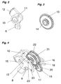
- the shift finger 6 is shown in FIG. 2 . It is connected to the hub 10, which is seated on the selector shaft 1 and pinned to the selector shaft 1 via the pin hole 11, and is therefore immovably and non-rotatably connected. Also on the hub is the toothing 12, which establishes the gear connection to the flywheel gear 7.
- the flywheel transmission 7 consists essentially of three identical gear modules including the associated axes. Such a gear module is shown in perspective in FIG. 3 . It consists of a gear 13 and a pinion 14 flanged to it, both of which have a common axis.
- FIG. 4 shows the structure of the flywheel transmission in the guide part 8.
- Guide part 8 and shift finger 6 are mounted together on the shift shaft 1 by means of the shift shaft bore 15 of the guide part 8 and the hub 10. While the hub 10 is rotatably connected to the selector shaft 1, the selector shaft 1 is rotatably arranged in the guide part 8. Hub 10 and guide part 8 are immovable on the selector shaft 1 in the axial direction of the selector shaft 1.
- the guide part 8 engages with the recess 16 in the guide pin 9 and is on the one hand rotatably mounted to the gear housing and on the other hand slidably in the axial direction of the shift shaft 1 to the gear housing.
- guide part 8 and shift finger 6 are simultaneously displaced in the axial direction of shift shaft 1.
- the shift finger 6 rotates with the shift shaft 1, while the guide part 8 remains in the recess 16 due to the bearing. This relative rotary movement between the shift finger 6 and the guide part 8 is used for the flywheel drive.
- the shift finger 6 on the hub 10 has the toothing 12, which with the pinion 17 of the drive gear 18 meshes.
- the flywheel 22 takes over Function of the flywheel and is in no other gear gear connection. All gears are on axes 23 in Guide part 8 supported, drive gear 18 and flywheel 22nd have a common axis. So the flywheel transmission builds a lot compact and only requires two different components, namely twice that Axis 23 and three times the gear module. The storage of the axes 23 in Guide part 8 does not require any additional parts. By means of the Flywheel transmission will function the additional mass at low cost, low additional weight and space requirements.
Landscapes
- Engineering & Computer Science (AREA)
- General Engineering & Computer Science (AREA)
- Mechanical Engineering (AREA)
- Gear-Shifting Mechanisms (AREA)
Abstract
Description
Die Erfindung bezieht sich auf eine Schaltvorrichtung für ein Gangwechselgetriebe, insbesondere in Kraftfahrzeugen, mit einer drehbaren und axial verschieblichen Schaltwelle zur Auswahl der Gangstufen, wobei die Schaltwelle mit einem Handschalthebel und mit Zusatzmassen kinematisch verbunden ist derart, daß Kraftspitzen am Handschalthebel während der einzelnen Schaltvorgänge abgebaut werden.The invention relates to a switching device for a Gear change transmission, in particular in motor vehicles, with a rotatable and axially displaceable shift shaft to select the gear stages, the Shift shaft with a manual shift lever and additional masses kinematic is connected such that force peaks on the manual shift lever during the individual switching operations are dismantled.
Heutige Schaltvorrichtungen weisen sehr große Zusatzmassen auf, die ein angenehmes Schaltgefühl beim Einlegen der einzelnen Gangstufen erzeugen indem sie die Betätigung der Gangschaltung durch ihre Massenträgheit unterstützen. Zur Reduzierung dieser Zusatzmassen wird in der DE 19523141 vorgeschlagen, die Zusatzmassen über eine Hebelgetriebe anzutreiben und damit die Massenträgheit durch die Übersetzung besser auszunutzen. Trotz der Hebelwirkung ist jedoch immer noch eine bestimmte Masse notwendig, da ein beliebiges Übersetzungsverhältnis nicht einfach realisierbar ist. Nachteilig ist auch, daß das Hebelgetriebe außen am Getriebegehäuse im Bereich des Schalthebels angebracht ist und deshalb gegen Verschmutzung geschützt bzw. entsprechend robust und damit schwer ausgelegt werden muß.Today's switching devices have very large additional masses Generate a pleasant shift feeling when engaging the individual gear stages by actuating the gear shift through its inertia support. To reduce these additional masses, DE 19523141 proposed to drive the additional masses via a lever gear and so that the inertia can be better exploited through the translation. Despite the However, leverage still requires a certain mass, as a any gear ratio is not easy to implement. The disadvantage is also that the lever gear on the outside of the gear housing in the area of Shift lever is attached and therefore protected against contamination or must be designed accordingly robust and therefore heavy.
Aufgabe der vorliegenden Erfindung ist es deshalb, eine Schaltvorrichtung der eingangs genannten Art zu schaffen, die nur unwesentliche Zusatzmassen benötigt und die robust ausgeführt werden kann.The object of the present invention is therefore to provide a switching device to create the kind mentioned above, the only insignificant additional masses needed and which can be made robust.
Diese Aufgabe wird gelöst, indem die Zusatzmasse ein Schwungradgetriebe ist, welches mit der Schaltwelle getrieblich verbunden ist. Dabei kann das Schwungradgetriebe mit der Schaltwelle sowohl in Drehrichtung der Schaltwelle als auch in Axialrichtung der Schaltwelle getrieblich verbunden sein. Im ersteren Fall wird der Einrückvorgang unterstützt, im letzteren die Auswahl der Schaltgassen.This object is achieved in that the additional mass is a flywheel gear, which is geared to the selector shaft. It can Flywheel gearbox with the selector shaft both in the direction of rotation of the selector shaft as well as be connected in the axial direction of the selector shaft. In the former In this case, the engagement process is supported, in the latter the selection of the Switching lanes.
Der Vorteil des Schwungradgetriebes ist, daß selbst bei geringem Gewicht ein hohes Drehträgheitsmoment am Ausgang des Schwungradgetriebes wirkt und damit die relative kleinen Bewegungen der Schaltwelle sehr gleichmäßig ablaufen. Ein Schwungradgetriebe kann, abhängig von der Anzahl der Radsätze, mit beliebigem Übersetzungsverhältnis ausgeführt sein. Damit wird bei sehr kleinem Gewicht ein sehr großes Drehträgheitsmoment erzeugt. Im Vergleich zu bestehenden Schaltvorrichtungen lassen sich so über 90 % des Gewichtes der Zusatzmassen einsparen.The advantage of the flywheel transmission is that even with a low weight high moment of inertia at the output of the flywheel gear acts and so the relatively small movements of the selector shaft are very even expire. A flywheel gearbox can, depending on the number of Wheelsets with any gear ratio. So that will generates a very large torsional moment of inertia with a very low weight. in the Compared to existing switching devices, over 90% of the Save the weight of the additional masses.
Die Wirkung des Schwungradgetriebes besteht im wesentlichen darin, ein angenehmes Schaltgefühl beim Einlegen des Ganges zu erzeugen. Beim Beginn des Einrückvorganges treibt die Drehung der Schaltwelle das Schwungradgetriebe an, wodurch am Handschalthebel direkt ein bestimmter, als angenehm empfundener Betätigungsdruck erfahren wird. Sobald die Schaltwelle und damit das Schwungradgetriebe in Drehung versetzt ist, kommt der Punkt, wo die Synchronisiereinrichtung beginnt den Gang einzurücken, was aber der Drehung der Schaltwelle einen plötzlichen Widerstand entgegensetzt. Die Drehträgheit des Schwungradgetriebes hilft, diesen Widerstand zu überwinden ohne das am Handschalthebel ein größerer Widerstand zu spüren ist. Das Einrücken eines Ganges selber benötigt eine Kraft, die vom Schwungradgetriebe bis zu dessen Stillstand unterstützt wird. Insgesamt wird durch das Schwungradgetriebe der empfundene Kraftverlauf am Handschalthebel während des Gangeinlegens egalisiert; es entsteht das besagte angenehme Schaltgefühl.The effect of the flywheel gearbox is essentially one To create a pleasant shift feeling when shifting into gear. At the The start of the engagement process drives the rotation of the selector shaft Flywheel gearbox, which means that a specific one is directly on the gear lever pleasant operating pressure is experienced. Once the shift shaft and so that the flywheel gear is rotated, the point comes where the synchronizer begins to engage the gear, but what the Rotation of the control shaft opposes a sudden resistance. The The inertia of the flywheel gear helps to overcome this resistance without feeling a greater resistance on the manual shift lever. The Engaging a gear itself requires a force from the flywheel gear is supported until it comes to a standstill. Overall, through that Flywheel gearbox the perceived force curve on the manual gear lever during equalized in gear; the above-mentioned pleasant shift feeling arises.
Vorzugsweise ist das Schwungradgetriebe im Getriebegehäuse angeordnet. Der geringe Platzbedarf eines Schwungradgetriebes ermöglicht die Anbringung an einer beliebigen Stelle im Getriebegehäuse, wo eine getriebliche Verbindung zur Schaltwelle ausführbar ist. Weiterer Vorteil ist, daß im Getriebegehäuse keine Kapselung und keine Abdichtung des Schwungradgetriebes für die Schmierung bzw. gegen Verschmutzung vorgesehen werden muß.The flywheel transmission is preferably arranged in the transmission housing. The Small space requirement of a flywheel gear enables attachment to anywhere in the gear housing, where a gear connection to Shift shaft is executable. Another advantage is that none in the gearbox Encapsulation and no sealing of the flywheel gear for lubrication or must be provided against pollution.
Bei einer vorteilhaften Ausgestaltung der Erfindung ist das Schwungradgetriebe auf der Schaltwelle unverschieblich in Axialrichtung der Schaltwelle angeordnet. Damit entfallen für die getriebliche Verbindung zwischen Schwungradgetriebe und Schaltwelle verschiebbare Übertragsmittel wie Schiebekupplungen oder Schiebezahnräder. Das Gehäuse des Schwungradgetriebes ist drehfest zum Getriebegehäuse angeordnet, bleibt aber in Axialrichtung der Schaltwelle gegenüber dem Getriebegehäuse verschiebbar. Das Gehäuse des Schwungradgetriebes selbst kann in auf der Schaltwelle angeordneten Schaltmitteln integriert sein.In an advantageous embodiment of the invention, the flywheel transmission arranged on the shift shaft immovably in the axial direction of the shift shaft. This eliminates the connection between the flywheel transmission and shift shaft displaceable transmission means such as sliding couplings or Sliding gears. The housing of the flywheel gearbox is non-rotatable for Gearbox housing arranged, but remains in the axial direction of the selector shaft slidable relative to the gear housing. The housing of the Flywheel gear itself can be arranged in on the selector shaft Switching means can be integrated.
Für eine kostengünstige Ausgestaltung der Erfindung besteht das Schwungradgetriebe aus einem Satz gleicher Zahnradmodule. Ein Zahnradmodul besteht aus einem kleinen Ritzel und einem großen Zahnrad, beide nebeneinander auf der gleichen Achse angeordnet und drehfest verbunden. Solche Zahnradmodule können in einem Stück z. B. als Kunststoffspritzguß, als Feinstanzteil oder als Sintermetallpreßteil hergestellt werden. Mehrere dieser Module werden wie ein Schwungradgetriebe in einem Gehäuse angeordnet, wobei das Zahnradmodul mit der höchsten bzw. letzten Übersetzungstufe die Hauptanteile der Funktion des Schwungrades übernimmt.For an inexpensive embodiment of the invention, there is Flywheel gear from a set of identical gear modules. On Gear module consists of a small pinion and a large gear, both arranged side by side on the same axis and non-rotatable connected. Such gear modules can in one piece, for. B. as Plastic injection molding, manufactured as a fine stamped part or as a sintered metal pressed part become. Several of these modules are like a flywheel transmission in one Housing arranged, the gear module with the highest or last Gear ratio takes over the main parts of the function of the flywheel.
Eine weitere vorteilhafte Ausgestaltung sieht vor, daß das Schwungradgetriebe direkt mit dem Schaltfinger, der die Schaltgabeln betätigt, getrieblich verbunden ist. Dies ergibt eine kompakte Bauweise und einen sehr direkten Antrieb des Schaltfingers durch das Schwungradgetriebe. Bevorzugt weist der Schaltfinger dafür eine Verzahnung auf, die mit einem Zahnrad des Schwungradgetriebes kämmt.A further advantageous embodiment provides that the flywheel transmission directly connected to the shift finger that actuates the shift forks is. This results in a compact design and a very direct drive of the Shift finger through the flywheel gear. The shift finger preferably has therefor a toothing with a gear wheel of the flywheel gear combs.
Weitere Einzelheiten ergeben sich aus der nachstehenden Beschreibung einer in den Zeichnungen dargestellten Ausführungsform der Erfindung. Es zeigen:
- Fig. 1
- eine perspektivische Darstellung einer erfindungsgemäßen Schaltvorrichtung mit Schwungradgetriebe;
- Fig. 2
- eine perspektivische Ansicht des Schaltfingers mit Verzahnung;
- Fig. 3
- eine perspektivische Ansicht eines Zahnradmodules; und
- Fig. 4
- eine perspektivische Ansicht des Schwungradgetriebes.
- Fig. 1
- a perspective view of a switching device according to the invention with flywheel gear;
- Fig. 2
- a perspective view of the shift finger with teeth;
- Fig. 3
- a perspective view of a gear module; and
- Fig. 4
- a perspective view of the flywheel transmission.
In Fig. 1 ist der Zusammenbau einer Schaltvorrichtung, wie sie bei einem
Gangwechselgetriebe zum Einsatz kommt, perspektivisch dargestellt. Die
Schaltwelle 1 ist gelagert im Schaltvorrichtungsdeckel 2 und am anderen Ende
in einer Führungsbuchse 3, welche wiederum im nicht dargestellten
Getriebegehäuse gelagert ist. Der Antrieb der Schaltwelle 1 erfolgt über den
Schalthebel 4 für die axiale Verschiebung der Schaltwelle 1 zur Auswahl der
Schaltgasse und dem Schalthebel 5 für die Drehbewegung der Schaltwelle 1 für
das Einrücken der Gänge. Auf der Schaltwelle 1 ist der Schaltfinger 6
angeordnet, der auf die Schaltgabeln, hier nicht dargestellt, die Bewegung der
Schaltwelle 1 überträgt.In Fig. 1 , the assembly of a switching device, such as is used in a gear change transmission, is shown in perspective. The
Direkt am Schaltfinger 6 ist auf der Schaltwelle 1 das Schwungradgetriebe 7,
welches mit dem Schaltfinger 6 in getrieblicher Verbindung steht, angeordnet.
Als Lagergehäuse des Schwungradgetriebes 7 dient das um den Schaltfinger 6
auf der Schaltwelle 1 angeordnete Führungsteil 8, das zusammen mit der
Schaltwelle 1 in Axialrichtung der Schaltwelle 1 verschoben werden kann, von
der Drehbewegung der Schaltwelle 1 entkoppelt ist und sich dazu an einem
Ende an einem im Getriebegehäuse verankerten Führungsstift 9 abstützt.Directly on the
In Fig. 2 ist der Schaltfinger 6 dargestellt. Er ist mit der Nabe 10 verbunden, die
auf der Schaltwelle 1 sitzt und über das Stiftloch 11 mit der Schaltwelle 1
verstiftet und damit unverückbar und drehfest verbunden ist. Ebenfalls auf der
Nabe ist die Verzahnung 12 angebracht, welche die getriebliche Verbindung
zum Schwungradgetriebe 7 herstellt.The
Das Schwungradgetriebe 7 besteht im wesentlichen aus drei gleichen
Zahnradmodulen einschließlich der zugehörigen Achsen. In Fig. 3 ist ein solches
Zahnradmodul perspektivisch abgebildet. Es besteht aus einem Zahnrad 13 und
einem daran angeflanschten Ritzel 14, die beide eine gemeinsame Achse
aufweisen.The
In Fig. 4 ist der Aufbau des Schwungradgetriebes im Führungsteil 8 gezeigt.
Führungsteil 8 und Schaltfinger 6 sind gemeinsam auf der Schaltwelle 1 mittels
der Schaltwellenbohrung 15 des Führungsteiles 8 und der Nabe 10 gelagert.
Während die Nabe 10 drehfest mit der Schaltwelle 1 verbunden ist, ist die
Schaltwelle 1 im Führungsteil 8 drehbar angeordnet. Nabe 10 und
Führungsteil 8 sind auf der Schaltwelle 1 in Axialrichtung der Schaltwelle 1
gesehen unverrückbar. Das Führungsteil 8 greift mit der Aussparung 16 in den
Führungsstift 9 ein und ist so zum einen drehfest zum Getriebegehäuse und
zum anderen in Axialrichtung der Schaltwelle 1 verschieblich zum
Getriebegehäuse gelagert. Bei der Auswahl der Schaltgasse während des
Schaltvorganges werden damit Führungsteil 8 und Schaltfinger 6 gleichzeitig in
Axialrichtung der Schaltwelle 1 verschoben. Beim Einrücken eines Ganges dreht
sich der Schaltfinger 6 mit der Schaltwelle 1, während das Führungsteil 8 durch
die Lagerung in der Aussparung 16 stehenbleibt. Diese relative Drehbewegung
zwischen Schaltfinger 6 und Führungsteil 8 wird für den Schwungradantrieb
ausgenutzt. 4 shows the structure of the flywheel transmission in the
Dazu weist der Schaltfinger 6 auf der Nabe 10 die Verzahnung 12 auf, die mit
dem Ritzel 17 des Antriebszahnrades 18 kämmt. Dieses kämmt mit dem
Ritzel 19 des Zwischenzahnrades 20, welches wiederum mit dem Ritzel 21 des
Schwungzahnrades 22 kämmt. Das Schwungzahnrad 22 übernimmt die
Funktion des Schwungrades und steht mit keinem anderen Zahnrad in
getrieblicher Verbindung. Alle Zahnräder sind auf den Achsen 23 im
Führungsteil 8 gelagert, wobei Antriebszahnrad 18 und Schwungzahnrad 22
eine gemeinsame Achse aufweisen. Damit baut das Schwungradgetriebe sehr
kompakt und benötigt nur zwei verschiedene Bauteile, nämlich zweimal die
Achse 23 und dreimal das Zahnradmodul. Die Lagerung der Achsen 23 im
Führungsteil 8 erfordert keine zusätzlichen Teile. Mittels des
Schwungradgetriebes wird die Funktion der Zusatzmasse mit geringen Kosten,
geringem Zusatzgewicht und geringem Platzbedarf realisiert.For this purpose, the
Claims (9)
dadurch gekennzeichnet, daß
die Zusatzmasse ein Schwungradgetriebe (7) ist, welches mit der Schaltwelle (1) getrieblich verbunden ist.Switching device for a gear change transmission, in particular in motor vehicles, with a rotatable and axially displaceable shift shaft (1) for selecting the gear stages, the shift shaft (1) being kinematically connected to a manual shift lever and with additional masses in such a way that force peaks on the manual shift lever are reduced during the individual shift processes become,
characterized in that
the additional mass is a flywheel gear (7), which is geared to the selector shaft (1).
dadurch gekennzeichnet, daß
das Schwungradgetriebe(7) mit der Schaltwelle(1) in Drehrichtung der Schaltwelle (1) getrieblich verbunden ist.Switching device according to claim 1,
characterized in that
the flywheel gear (7) is operatively connected to the selector shaft (1) in the direction of rotation of the selector shaft (1).
dadurch gekennzeichnet, daß
das Schwungradgetriebe mit der Schaltwelle (1) in Axialrichtung der Schaltwelle (1) getrieblich verbunden ist.Switching device according to claim 1,
characterized in that
the flywheel transmission is connected to the shift shaft (1) in the axial direction of the shift shaft (1).
dadurch gekennzeichnet, daß
das Schwungradgetriebe (7) im Getriebegehäuse angeordnet ist.Switching device according to claim 1,
characterized in that
the flywheel gear (7) is arranged in the gear housing.
dadurch gekennzeichnet, daß
das Schwungradgetriebe (7) ortsfest zum Getriebegehäuse angeordnet ist. Switching device according to claim 1,
characterized in that
the flywheel gear (7) is fixed to the gear housing.
dadurch gekennzeichnet, daß
das Schwungradgetriebe (7) auf der Schaltwelle (1) unverschieblich in Axialrichtung der Schaltwelle (1) angeordnet ist.Switching device according to claim 2,
characterized in that
the flywheel gear (7) is arranged on the selector shaft (1) so that it cannot move in the axial direction of the selector shaft (1).
dadurch gekennzeichnet, daß
das Schwungradgetriebe (7) aus einem Satz gleicher Zahnradmodule besteht.Switching device according to claim 1,
characterized in that
the flywheel gear (7) consists of a set of identical gear modules.
dadurch gekennzeichnet, daß
ein Schaltfinger (6) direkt mit dem Schwungradgetriebe (7) in getrieblicher Verbindung steht.Switching device according to claim 1,
characterized in that
a shift finger (6) is directly connected to the flywheel transmission (7).
dadurch gekennzeichnet, daß
der Schaltfinger (8) eine Verzahnung aufweist, die mit einem Zahnrad des Schwungradgetriebes (7) kämmt.Switching device according to claim 8,
characterized in that
the shift finger (8) has a toothing which meshes with a gear of the flywheel transmission (7).
Priority Applications (3)
| Application Number | Priority Date | Filing Date | Title |
|---|---|---|---|
| EP20000100522 EP1116902B1 (en) | 2000-01-12 | 2000-01-12 | Ratio shift mechanism for a change speed gearbox |
| ES00100522T ES2161208T3 (en) | 2000-01-12 | 2000-01-12 | RELATIONSHIP CHANGE MECHANISM FOR A GEARBOX. |
| DE50000006T DE50000006D1 (en) | 2000-01-12 | 2000-01-12 | Switching device for a gear change transmission |
Applications Claiming Priority (1)
| Application Number | Priority Date | Filing Date | Title |
|---|---|---|---|
| EP20000100522 EP1116902B1 (en) | 2000-01-12 | 2000-01-12 | Ratio shift mechanism for a change speed gearbox |
Publications (2)
| Publication Number | Publication Date |
|---|---|
| EP1116902A1 true EP1116902A1 (en) | 2001-07-18 |
| EP1116902B1 EP1116902B1 (en) | 2001-08-01 |
Family
ID=8167604
Family Applications (1)
| Application Number | Title | Priority Date | Filing Date |
|---|---|---|---|
| EP20000100522 Expired - Lifetime EP1116902B1 (en) | 2000-01-12 | 2000-01-12 | Ratio shift mechanism for a change speed gearbox |
Country Status (3)
| Country | Link |
|---|---|
| EP (1) | EP1116902B1 (en) |
| DE (1) | DE50000006D1 (en) |
| ES (1) | ES2161208T3 (en) |
Cited By (12)
| Publication number | Priority date | Publication date | Assignee | Title |
|---|---|---|---|---|
| FR2833540A1 (en) * | 2001-12-14 | 2003-06-20 | Peugeot Citroen Automobiles Sa | Return element for gearbox gear change mechanism comprises monobloc body on which ball joint engaging selection rod end is fixed, and inertia device comprising inertia roller which decreases gear selection force |
| DE10210972A1 (en) * | 2002-03-13 | 2003-10-09 | Daimler Chrysler Ag | Gear shift device for vehicle has movement of shift shaft transferred to auxiliary mass with variation in accordance with setting |
| FR2864477A1 (en) * | 2003-12-24 | 2005-07-01 | Itw Bailly Comte | Gear shifting assisting device for gearbox of vehicle, has rear parcel and disc surfaces and spring assuring selective integration between disc and transmission units, when disc`s angular acceleration is less than preset value |
| FR2865165A1 (en) * | 2004-01-21 | 2005-07-22 | Dura Automotive Systems | Speed shifting support device for mechanical gearbox of motor vehicle, has arm driving mass to transmit acceleration movement for facilitating shifting, and axle placed in arm`s center part to delimit coupling and driving units |
| EP1710474A1 (en) * | 2005-04-06 | 2006-10-11 | Peugeot Citroen Automobiles SA | Schalteinrichtung zur Betätigung eines manuellen Schaltgetriebes |
| WO2007137895A1 (en) * | 2006-05-26 | 2007-12-06 | Schaeffler Kg | Shift device for a gearbox |
| DE102006050935A1 (en) * | 2006-10-28 | 2008-04-30 | Schaeffler Kg | Contactor, has operating shaft and additional mass, which are rotatably supported with each other by separate rotation axes, where additional mass is coupled with operating shaft by clinch drive |
| DE102009054725A1 (en) * | 2009-12-16 | 2011-06-22 | ZF Friedrichshafen AG, 88046 | Switching device for gearbox of motor vehicle, has selector shaft, where gear selection is performed by axial movement and switching movement through rotational movement of selector shaft |
| WO2012019798A1 (en) * | 2010-08-13 | 2012-02-16 | Schaeffler Technologies Gmbh & Co. Kg | Shifting device for a transmission |
| DE102013209641A1 (en) * | 2013-05-24 | 2014-12-11 | Schaeffler Technologies Gmbh & Co. Kg | Switching device for a change-speed gearbox of a motor vehicle |
| DE102013214956A1 (en) * | 2013-07-31 | 2015-02-19 | Schaeffler Technologies Gmbh & Co. Kg | Switching device for a transmission |
| DE102017128965A1 (en) | 2017-12-06 | 2019-06-06 | Schaeffler Technologies AG & Co. KG | switching device |
Families Citing this family (8)
| Publication number | Priority date | Publication date | Assignee | Title |
|---|---|---|---|---|
| DE102011004417A1 (en) | 2011-02-18 | 2012-08-23 | Schaeffler Technologies Gmbh & Co. Kg | Switching arrangement for manual transmission of motor vehicle, has transmission element that is operatively arranged between switching shaft and actuating unit that moves switching shaft with respect to pivot axis |
| DE102011089004A1 (en) | 2011-12-19 | 2013-06-20 | Schaeffler Technologies AG & Co. KG | Switching device for change of transmission in motor vehicle, has additional mass of inertia for equalization of power peaks, where movement of additional mass of inertia is delayed by braking unit |
| DE102012220999A1 (en) | 2012-11-16 | 2014-05-22 | Schaeffler Technologies Gmbh & Co. Kg | Switching device i.e. switching dome, for gear wheel change speed gear of vehicle i.e. motor car, has center part i.e. front-sided cover, including centering unit, where center part positions two of wheels relative to each other |
| DE102012220998B4 (en) | 2012-11-16 | 2015-01-22 | Schaeffler Technologies Gmbh & Co. Kg | Switching device for a transmission |
| DE102012220994B4 (en) | 2012-11-16 | 2015-02-26 | Schaeffler Technologies Gmbh & Co. Kg | Switching device for a transmission |
| DE102012220988B4 (en) | 2012-11-16 | 2016-06-30 | Schaeffler Technologies AG & Co. KG | Switching device for a transmission |
| WO2014075672A1 (en) | 2012-11-16 | 2014-05-22 | Schaeffler Technologies AG & Co. KG | Switching device for a gearbox |
| DE102012221000A1 (en) | 2012-11-16 | 2014-05-22 | Schaeffler Technologies Gmbh & Co. Kg | Switching device for a transmission |
Citations (4)
| Publication number | Priority date | Publication date | Assignee | Title |
|---|---|---|---|---|
| US3983965A (en) * | 1975-07-07 | 1976-10-05 | Pacific Scientific Company | Adjustable locking strut |
| JPH03260412A (en) * | 1990-03-08 | 1991-11-20 | Nippon Cable Syst Inc | End structure of control cable |
| DE19523141A1 (en) * | 1995-06-28 | 1997-01-02 | Daimler Benz Ag | Gearchange mechanism for automotive gearbox |
| US5791194A (en) * | 1995-12-13 | 1998-08-11 | Mercedes-Benz Ag | Shift device for a motor vehicle gear change transmission |
-
2000
- 2000-01-12 ES ES00100522T patent/ES2161208T3/en not_active Expired - Lifetime
- 2000-01-12 DE DE50000006T patent/DE50000006D1/en not_active Expired - Lifetime
- 2000-01-12 EP EP20000100522 patent/EP1116902B1/en not_active Expired - Lifetime
Patent Citations (4)
| Publication number | Priority date | Publication date | Assignee | Title |
|---|---|---|---|---|
| US3983965A (en) * | 1975-07-07 | 1976-10-05 | Pacific Scientific Company | Adjustable locking strut |
| JPH03260412A (en) * | 1990-03-08 | 1991-11-20 | Nippon Cable Syst Inc | End structure of control cable |
| DE19523141A1 (en) * | 1995-06-28 | 1997-01-02 | Daimler Benz Ag | Gearchange mechanism for automotive gearbox |
| US5791194A (en) * | 1995-12-13 | 1998-08-11 | Mercedes-Benz Ag | Shift device for a motor vehicle gear change transmission |
Non-Patent Citations (1)
| Title |
|---|
| PATENT ABSTRACTS OF JAPAN vol. 016, no. 072 (M - 1213) 21 February 1992 (1992-02-21) * |
Cited By (17)
| Publication number | Priority date | Publication date | Assignee | Title |
|---|---|---|---|---|
| FR2833540A1 (en) * | 2001-12-14 | 2003-06-20 | Peugeot Citroen Automobiles Sa | Return element for gearbox gear change mechanism comprises monobloc body on which ball joint engaging selection rod end is fixed, and inertia device comprising inertia roller which decreases gear selection force |
| DE10210972A1 (en) * | 2002-03-13 | 2003-10-09 | Daimler Chrysler Ag | Gear shift device for vehicle has movement of shift shaft transferred to auxiliary mass with variation in accordance with setting |
| DE10210972B4 (en) * | 2002-03-13 | 2006-07-06 | Daimlerchrysler Ag | switching device |
| FR2864477A1 (en) * | 2003-12-24 | 2005-07-01 | Itw Bailly Comte | Gear shifting assisting device for gearbox of vehicle, has rear parcel and disc surfaces and spring assuring selective integration between disc and transmission units, when disc`s angular acceleration is less than preset value |
| FR2865165A1 (en) * | 2004-01-21 | 2005-07-22 | Dura Automotive Systems | Speed shifting support device for mechanical gearbox of motor vehicle, has arm driving mass to transmit acceleration movement for facilitating shifting, and axle placed in arm`s center part to delimit coupling and driving units |
| EP1557592A1 (en) * | 2004-01-21 | 2005-07-27 | Dura Automotive Systems | Shift control apparatus for transmission of a vehicle |
| EP1710474A1 (en) * | 2005-04-06 | 2006-10-11 | Peugeot Citroen Automobiles SA | Schalteinrichtung zur Betätigung eines manuellen Schaltgetriebes |
| FR2884291A1 (en) * | 2005-04-06 | 2006-10-13 | Peugeot Citroen Automobiles Sa | CONTROL DEVICE FOR MANUAL TRANSMISSION |
| WO2007137895A1 (en) * | 2006-05-26 | 2007-12-06 | Schaeffler Kg | Shift device for a gearbox |
| DE102006050935A1 (en) * | 2006-10-28 | 2008-04-30 | Schaeffler Kg | Contactor, has operating shaft and additional mass, which are rotatably supported with each other by separate rotation axes, where additional mass is coupled with operating shaft by clinch drive |
| DE102009054725A1 (en) * | 2009-12-16 | 2011-06-22 | ZF Friedrichshafen AG, 88046 | Switching device for gearbox of motor vehicle, has selector shaft, where gear selection is performed by axial movement and switching movement through rotational movement of selector shaft |
| WO2012019798A1 (en) * | 2010-08-13 | 2012-02-16 | Schaeffler Technologies Gmbh & Co. Kg | Shifting device for a transmission |
| DE102013209641A1 (en) * | 2013-05-24 | 2014-12-11 | Schaeffler Technologies Gmbh & Co. Kg | Switching device for a change-speed gearbox of a motor vehicle |
| DE102013209641B4 (en) * | 2013-05-24 | 2015-07-30 | Schaeffler Technologies AG & Co. KG | Switching device for a change-speed gearbox of a motor vehicle |
| DE102013214956A1 (en) * | 2013-07-31 | 2015-02-19 | Schaeffler Technologies Gmbh & Co. Kg | Switching device for a transmission |
| DE102013214956B4 (en) * | 2013-07-31 | 2018-05-17 | Schaeffler Technologies AG & Co. KG | Switching device for a transmission |
| DE102017128965A1 (en) | 2017-12-06 | 2019-06-06 | Schaeffler Technologies AG & Co. KG | switching device |
Also Published As
| Publication number | Publication date |
|---|---|
| DE50000006D1 (en) | 2001-09-27 |
| EP1116902B1 (en) | 2001-08-01 |
| ES2161208T3 (en) | 2001-12-01 |
Similar Documents
| Publication | Publication Date | Title |
|---|---|---|
| EP1116902B1 (en) | Ratio shift mechanism for a change speed gearbox | |
| DE3525208A1 (en) | REDUCTION GEARBOX | |
| DE3150885C2 (en) | ||
| DE102019123288A1 (en) | Gear shift for an electromotive auxiliary bicycle drive | |
| DE2447190C3 (en) | Manually operated crank and drive mechanism for a lift and slide cover of a motor vehicle | |
| WO2003055359A1 (en) | Furniture drive for adjusting parts of an item of furniture in relation to each other | |
| EP0617910B1 (en) | Drive unit for kitchen apparatus | |
| EP0040261A1 (en) | Electrical tool with a two-speed gear | |
| EP1097657B1 (en) | Telescopic driving unit | |
| DE19822666B4 (en) | Device for actuating a pivotable about an axis and displaceable along the axis of the switching shaft of a gearbox | |
| DE68910890T2 (en) | MECHANISM AND ITS FUNCTIONING FOR POSITIONING A GEAR SHIFT LEVER IN PARKING POSITION. | |
| DE19701767A1 (en) | Auxiliary transmission for motor vehicle | |
| AT401282B (en) | MANUAL TRANSMISSION | |
| DE4446482C1 (en) | Rack=and=pinion drive system | |
| DE10340997B3 (en) | Rotary drive for adjusting vehicle seat has transmission shifted to smaller transmission ratio by service element | |
| DE102010048601A1 (en) | Input device with variable actuation feeling | |
| DE19907269A1 (en) | Automobile servo steering device has conversion gearing using worm shaft and worm wheel provided with spring element for damping operating noise | |
| DE102007027219A1 (en) | Linear driving mechanism for a motor vehicle's tailgate and front flap has a rotating threaded spindle and an electric motor as a drive unit | |
| DE4333726A1 (en) | Multiple adjustment devices drive unit - has electromotor for operating several adjustment devices via different selectable coupling elements | |
| DE10260548B4 (en) | Drive for a vehicle seat adjuster | |
| EP1387974B1 (en) | Valve drive | |
| DE19731011A1 (en) | Manual gear shift for motor vehicle | |
| DE10254125B4 (en) | Electromotive furniture drive for adjusting parts of a furniture relative to each other | |
| WO1991019119A1 (en) | Step-down gear for display instrument | |
| DE10003512B4 (en) | Device for supporting self-locking in electric motors |
Legal Events
| Date | Code | Title | Description |
|---|---|---|---|
| GRAG | Despatch of communication of intention to grant |
Free format text: ORIGINAL CODE: EPIDOS AGRA |
|
| GRAH | Despatch of communication of intention to grant a patent |
Free format text: ORIGINAL CODE: EPIDOS IGRA |
|
| PUAI | Public reference made under article 153(3) epc to a published international application that has entered the european phase |
Free format text: ORIGINAL CODE: 0009012 |
|
| GRAH | Despatch of communication of intention to grant a patent |
Free format text: ORIGINAL CODE: EPIDOS IGRA |
|
| GRAA | (expected) grant |
Free format text: ORIGINAL CODE: 0009210 |
|
| 17P | Request for examination filed |
Effective date: 20000801 |
|
| AK | Designated contracting states |
Kind code of ref document: A1 Designated state(s): DE ES FR GB IT SE |
|
| AX | Request for extension of the european patent |
Free format text: AL;LT;LV;MK;RO;SI |
|
| AK | Designated contracting states |
Kind code of ref document: B1 Designated state(s): DE ES FR GB IT SE |
|
| AX | Request for extension of the european patent |
Free format text: AL;LT;LV;MK;RO;SI |
|
| PG25 | Lapsed in a contracting state [announced via postgrant information from national office to epo] |
Ref country code: IT Free format text: LAPSE BECAUSE OF FAILURE TO SUBMIT A TRANSLATION OF THE DESCRIPTION OR TO PAY THE FEE WITHIN THE PRE;WARNING: LAPSES OF ITALIAN PATENTS WITH EFFECTIVE DATE BEFORE 2007 MAY HAVE OCCURRED AT ANY TIME BEFORE 2007. THE CORRECT EFFECTIVE DATE MAY BE DIFFERENT FROM THE ONE RECORDED.SCRIBED TIME-LIMIT Effective date: 20010801 |
|
| REF | Corresponds to: |
Ref document number: 50000006 Country of ref document: DE Date of ref document: 20010927 |
|
| PG25 | Lapsed in a contracting state [announced via postgrant information from national office to epo] |
Ref country code: SE Free format text: LAPSE BECAUSE OF FAILURE TO SUBMIT A TRANSLATION OF THE DESCRIPTION OR TO PAY THE FEE WITHIN THE PRESCRIBED TIME-LIMIT Effective date: 20011101 |
|
| REG | Reference to a national code |
Ref country code: ES Ref legal event code: FG2A Ref document number: 2161208 Country of ref document: ES Kind code of ref document: T3 |
|
| EN | Fr: translation not filed | ||
| REG | Reference to a national code |
Ref country code: GB Ref legal event code: IF02 |
|
| REG | Reference to a national code |
Ref country code: FR Ref legal event code: RN |
|
| AKX | Designation fees paid |
Free format text: DE ES FR GB IT SE |
|
| PLBE | No opposition filed within time limit |
Free format text: ORIGINAL CODE: 0009261 |
|
| STAA | Information on the status of an ep patent application or granted ep patent |
Free format text: STATUS: NO OPPOSITION FILED WITHIN TIME LIMIT |
|
| 26N | No opposition filed | ||
| GBT | Gb: translation of ep patent filed (gb section 77(6)(a)/1977) |
Effective date: 20020628 |
|
| REG | Reference to a national code |
Ref country code: GB Ref legal event code: 9110 Free format text: EXTENSION ALLOWED: RATIO SHIFT MECHANISM FOR A CHANGE SPEED GEARBOX PERIOD(S) PRESCRIBED BY RULE(S) SCHEDULE 4 PARA 2 EXTENDED UNDER RULE 110(6) IN ACCORDANCE WITH THE DECISION OF THE COMPTROLLER DATED 18 FEB 2002. |
|
| REG | Reference to a national code |
Ref country code: FR Ref legal event code: FC |
|
| ET | Fr: translation filed | ||
| REG | Reference to a national code |
Ref country code: GB Ref legal event code: 732E |
|
| REG | Reference to a national code |
Ref country code: FR Ref legal event code: TP |
|
| PGFP | Annual fee paid to national office [announced via postgrant information from national office to epo] |
Ref country code: GB Payment date: 20091211 Year of fee payment: 11 Ref country code: ES Payment date: 20100115 Year of fee payment: 11 |
|
| PGFP | Annual fee paid to national office [announced via postgrant information from national office to epo] |
Ref country code: FR Payment date: 20100125 Year of fee payment: 11 |
|
| PGFP | Annual fee paid to national office [announced via postgrant information from national office to epo] |
Ref country code: DE Payment date: 20100129 Year of fee payment: 11 |
|
| GBPC | Gb: european patent ceased through non-payment of renewal fee |
Effective date: 20110112 |
|
| REG | Reference to a national code |
Ref country code: FR Ref legal event code: ST Effective date: 20110930 |
|
| PG25 | Lapsed in a contracting state [announced via postgrant information from national office to epo] |
Ref country code: FR Free format text: LAPSE BECAUSE OF NON-PAYMENT OF DUE FEES Effective date: 20110131 |
|
| PG25 | Lapsed in a contracting state [announced via postgrant information from national office to epo] |
Ref country code: GB Free format text: LAPSE BECAUSE OF NON-PAYMENT OF DUE FEES Effective date: 20110112 |
|
| REG | Reference to a national code |
Ref country code: DE Ref legal event code: R119 Ref document number: 50000006 Country of ref document: DE Effective date: 20110802 |
|
| REG | Reference to a national code |
Ref country code: ES Ref legal event code: FD2A Effective date: 20120220 |
|
| PG25 | Lapsed in a contracting state [announced via postgrant information from national office to epo] |
Ref country code: ES Free format text: LAPSE BECAUSE OF NON-PAYMENT OF DUE FEES Effective date: 20110113 |
|
| PG25 | Lapsed in a contracting state [announced via postgrant information from national office to epo] |
Ref country code: DE Free format text: LAPSE BECAUSE OF NON-PAYMENT OF DUE FEES Effective date: 20110802 |