EP1116982A2 - Séparateur de faisceaux optiques - Google Patents
Séparateur de faisceaux optiques Download PDFInfo
- Publication number
- EP1116982A2 EP1116982A2 EP00126376A EP00126376A EP1116982A2 EP 1116982 A2 EP1116982 A2 EP 1116982A2 EP 00126376 A EP00126376 A EP 00126376A EP 00126376 A EP00126376 A EP 00126376A EP 1116982 A2 EP1116982 A2 EP 1116982A2
- Authority
- EP
- European Patent Office
- Prior art keywords
- beam splitter
- incident radiation
- segments
- radiation
- surface segments
- Prior art date
- Legal status (The legal status is an assumption and is not a legal conclusion. Google has not performed a legal analysis and makes no representation as to the accuracy of the status listed.)
- Withdrawn
Links
Images


Classifications
-
- G—PHYSICS
- G02—OPTICS
- G02B—OPTICAL ELEMENTS, SYSTEMS OR APPARATUS
- G02B27/00—Optical systems or apparatus not provided for by any of the groups G02B1/00 - G02B26/00, G02B30/00
- G02B27/10—Beam splitting or combining systems
- G02B27/14—Beam splitting or combining systems operating by reflection only
- G02B27/144—Beam splitting or combining systems operating by reflection only using partially transparent surfaces without spectral selectivity
-
- G—PHYSICS
- G02—OPTICS
- G02B—OPTICAL ELEMENTS, SYSTEMS OR APPARATUS
- G02B27/00—Optical systems or apparatus not provided for by any of the groups G02B1/00 - G02B26/00, G02B30/00
- G02B27/10—Beam splitting or combining systems
- G02B27/1086—Beam splitting or combining systems operating by diffraction only
-
- G—PHYSICS
- G02—OPTICS
- G02B—OPTICAL ELEMENTS, SYSTEMS OR APPARATUS
- G02B27/00—Optical systems or apparatus not provided for by any of the groups G02B1/00 - G02B26/00, G02B30/00
- G02B27/10—Beam splitting or combining systems
- G02B27/14—Beam splitting or combining systems operating by reflection only
- G02B27/145—Beam splitting or combining systems operating by reflection only having sequential partially reflecting surfaces
Definitions
- the invention relates to a beam splitter according to the preamble of patent claim 1.
- Beam splitters are geometrical and physical Beam splitter can be divided.
- the incident ones Beams depending on the point of impact on the beam splitter into different emerging rays of radiation split.
- a geometric beam splitter e.g. a Flat plate shown, on which strip-shaped mirrors are applied.
- This faceplate is arranged at an angle of 45 ° to the incident radiation, so that the on Radiation incident and reflected radiation are perpendicular to the incident Radiation propagates, the radiation striking the non-mirrored areas the flat plate, due to the refraction on the front and back, depending on the optical density of the plane plate the beam splitter in relation to the incident radiation leaves laterally offset.
- furrow mirrors are known as geometric beam splitters, which on the incident light beam facing side with reflecting surface segments have opposite slope, through which a serrated surface is formed.
- the radiation striking this surface is divided into two different types Reflected spatial directions, which on the first mirror segments with a first Surface inclination radiation in a first spatial direction and that on the second mirror surface with an opposite slope or surface slope in the second spatial direction predetermined by the surface segments is reflected.
- the Angle between these bundles of reflected radiation corresponds to the angle at which the first and second surface segments to each other are arranged.
- one of two rhomboid prisms is included as a geometric beam splitter opposite spatial alignment of the formed beam splitter is known, by means of which a symmetrical aperture rating is provided.
- a disadvantage of these geometric beam splitters is that they are more geometric Beam splitter no proportional division of the incident radiation is possible represent proportional average over the radiation intensity.
- the physical beam splitters have partially reflecting surfaces on which a predetermined portion of the incident radiation is reflected, the remaining Share, apart from absorption losses, this partially reflecting layer unimpeded happens. These physical beam splitters are used to extract a portion of the incident light perpendicular to the incident beam at an angle of 45 ° to the arranged incident radiation.
- Beam splitters are often used in lenses, especially for semiconductor lithography, used to the from the radiation intensity of the coupled radiation To determine the radiation intensity of the transmitted radiation and thus the To determine the exposure intensity of the respective wafer or film.
- a geometric beam splitter is known from EP 484 801 A2, by means of which a Image is broken down into sub-segments using CCD arrays, which are standard components available are recorded. These recorded image segments become put together an overall picture. Such a geometric beam splitter will used especially when a recording of the image due to its Dimensions using a CCD array available as a standard component or other than Standard component available acquisition unit is not possible.
- the invention had for its object to provide a beam splitter, the Extension in the axial direction is minimized.
- the object of the invention was furthermore the object to further develop a beam splitter in such a way that the specification of the predetermined decoupled portion can be predetermined with increased accuracy.
- the object of the invention is given by that in claim 1 or 9 Features resolved.
- the partially reflecting surface segments are arranged parallel to each other, is an extremely short in the axial direction Beam splitter created by a predetermined proportion of the beam splitter incident radiation is coupled perpendicular to the incident radiation.
- Beam splitter created by a predetermined proportion of the beam splitter incident radiation is coupled perpendicular to the incident radiation.
- At vertical decoupling is possible by means of a parallel to the beam path arranged detector to detect the intensity of the outcoupled radiation.
- the partially reflecting surface segments a constant, non-zero distance, parallel to each other.
- the distance is preferably chosen such that the entire beam splitter incident radiation must pass through a partially reflecting surface or on the same is reflected, the partially reflecting surface segments being minimal or do not overlap.
- the partially reflecting surface segments of plan transparent support segments to be worn at an angle of 45 ° are arranged to the incident radiation.
- the rest are not at an angle of 45 ° to incident radiation arranged boundary surfaces of the transparent support segments are preferably arranged perpendicular to the incident radiation.
- plan transparent carrier segments those with partially reflecting surface segments are provided, in particular by vapor deposition of a transparent support, e.g. a glass carrier, and subsequent cutting process inexpensive to produce.
- a transparent support e.g. a glass carrier
- one transparent carrier preferably plan partially reflecting surface segments to separate. It is particularly by means of a varnish coating, which in some areas is cured by exposure to such partially reflecting surface segments to train. With appropriate selection of the paint, it is possible that the trained partially reflecting surface segments are only partially reflecting for certain wavelengths and are transmitted in the remaining wavelength range.
- a transparent one is provided Carrier on the side facing the incident radiation with a stair structure Mistake.
- This stair structure has first surface segments that are at an angle of Are arranged at 45 ° to the incident radiation. These are first surface segments via second surface segments, which are arranged parallel to the incident radiation, connected to one another, at least the first surface segments being partially reflective are.
- the transparent support provided with a stair structure is a cover support assign the opposite side on the incident radiation with an opposite trained stair structure is provided. With such an arrangement, the partially reflecting surface segments both on the cover beam and on the Glass carrier can be arranged.
- the cover carrier is preferred with the transparent carrier positively connected so that a beam splitter formed by these two elements on the side facing the incident radiation and on the side facing the incident Radiation-facing side has surfaces that are preferably perpendicular to incident radiation are arranged so that the incident radiation at this Surfaces are not bent.
- beam splitters For flat surfaces of the beam splitter, especially before assembly, easy to clean. Such beam splitters are also more stable and can because of their geometric shape can be packed more easily.
- the input intensity for a required resulting lighting intensity can accordingly be kept low, which is has a beneficial effect on the energy balance.
- a small Detector surface detector can be used. Also no need to bundle the decoupled light separate optics are provided, which is advantageous to the Costs.
- the measure of providing a carrier with a microstructure that has periodicity intervals creates a further beam splitter that is short in the axial direction.
- diffraction phenomena can be specifically decoupled for coupling out a predetermined proportion of the light incident on the beam splitter and used for determining the transmitted light intensity. It has proven to be advantageous to provide as a support a plate with surfaces oriented perpendicular to the incident radiation, the microstructure being arranged on the front of the plate.
- the periodicity intervals of the microstructure in this way to choose that the diffraction pattern resulting from these periodicity intervals Higher order diffraction maximum, the radiation at an angle strikes the surface of the plate facing away from the incident radiation, at which Total reflection occurs and thus the radiation is below the first diffraction maximum Total reflection is directed to the lateral boundary edge of the plate and exits there.
- the plate thus acts as a beam guide.
- a diffraction order as low as possible Order is predestined because it still has a relatively high intensity, which is very enables exact determination of the transmitted radiation intensity. It could however, the radiation of a higher diffraction order can also be coupled out, whereby however, higher radiation losses are accepted.
- the Intensity of the incident radiation or the radiation passing through the beam splitter determinable.
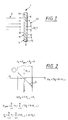
- the beam splitter 1 shown in FIG. 1 has partially reflecting surface segments 5, which are arranged at an angle of 45 ° to the incident radiation 3.
- This Partially reflecting surface segments 5 are perpendicular to the incident radiation 3 arranged level 4 laterally offset from each other, the partially reflecting surface segments 5 in turn parallel to each other with a constant Distance 7 are arranged.
- These partially reflecting surface segments 5 are from plan transparent support segments 9 worn. These transparent support segments 9 point on the side 10 facing the incident radiation 3 and on the side 12 facing away from incident radiation 3 each has an incident radiation 3 perpendicular boundary surfaces 11, 13. To reduce Radiation losses from scattering can limit these boundary surfaces 11, 13 with a Anti-reflective coating.
- a beam splitter 1 can already be in the form of a parallelogram trained transparent support segments 9, for example by means of vapor deposition partially reflective layer 19 are provided, through which the partially reflective Surface segments 5 are formed.
- This partially reflecting layer 19 can also be applied a transparent support 21, e.g. a glass plate, from which then the transparent carrier segments 9 are cut.
- This transparent carrier segments 9 are attached to the partially reflecting layer 19 provided and if necessary, if only one surface with a partially reflective layer is provided with the parallel surface 15 of the subsequent transparent Carrier segment 9 joined together, with the incident radiation 3 facing and facing boundary surfaces 11, 13 formed flat surfaces become.
- the remaining portion T * Pi is transmitted and is added to the radiation portion R * Po of the incident radiation 3 reflected on this partially reflecting surface segment 5, with numbering i + 1.
- the sum of the transmitted radiation is obtained by summing the number of partially reflected surface segments from 1 to N.
- the sum of the number N of the partially reflecting surface segments 5 gives the proportion of the incident radiation which propagates in the beam splitter perpendicular to the incident radiation and leaves the beam splitter laterally, perpendicular to the incident radiation.
- the proportion of the outcoupled radiation is designated P ⁇ (see FIG. 3).
- the proportion ⁇ of scattering losses which depends on the number N of the partially reflecting surface segments 5 can be determined by a calibration measurement.
- the beam splitter 1 shown in Figure 3 differs only in the structure of the Support structure on which the partially reflecting surface segments 5 are attached, the partially reflecting surface segments 5 from the point of view of the incident radiation 3 in are arranged in the same way.
- These partially reflecting surface segments 5 are however, carried by a glass carrier 21, which is based on that of the incident radiation 3 facing side has a stair structure 23, the surface segments 25 with has two orientations.
- First surface segments 27 are at an angle of 45 ° to Incident radiation 3 arranged, with second surface segments 29, over which the first surface segments 27 are connected to one another, forming a stair structure 23, are aligned parallel to the incident radiation 3.
- the partially reflective Surface segments 5 are carried by the first surface segments 27.
- a cover support 22 is assigned to the transparent support 21, which on the side facing away from the incident radiation 3 has a step structure 24 designed in the opposite direction to the stair structure 23 of the transparent support 21, the first surface segments 27 likewise being provided with a partially reflecting layer 19 can.
- a layer can be applied by vapor deposition.
- a plate 43 having parallel surfaces is formed, in which a layer comprising partially reflecting surface segments 5 is integrated.
- cover girder 22 and glass girder 21 are joined together by means of a cement connection.
- Such an integrated partially reflective layer can also be formed in a transparent carrier by an etching process.
- scattering losses can be achieved by providing a Anti-reflective coating on the surface 45 arranged perpendicular to the incident radiation 3, be reduced.
- the exemplary embodiment shown in FIG. 4 is shown from the viewing direction of the incident radiation 3.
- the partially reflecting surface segments 5 arranged at an angle of 45 ° to the incident radiation 3 are arranged co-axially to a focus 31, which is arranged outside the beam path of the incident radiation 3, for focusing the portion P ⁇ to be coupled out.
- a detector 33 is provided in focus 31 for detecting the intensity of the coupled-out portion P ⁇ of the incident radiation 3. Except for minimal scattering losses, this radiation is completely detected by the detector.
- a detector 33 which has a small-sized detector surface 34, is sufficient to sense this intensity.
- FIGS. 5 and 6 An exemplary embodiment of a beam splitter 1 is shown with reference to FIGS. 5 and 6 described, the one provided with a microstructure 39 as a periodic structure 37 Surface 45 has.
- the periodicity intervals 41 of the microstructure 39 are shown in FIG Dependence on the wavelength at which the beam splitter is to be used chosen so that the microstructure 39 results in a diffraction pattern.
- This microstructure 39 is on a plate 43, e.g. by means of a lacquer coating or applied by an etching process.
- This microstructure points parallel to each other and surfaces 46, 47 oriented perpendicular to the incident radiation 3, wherein a Higher order diffraction maxima at such a shallow angle to that of the incident radiation 3 facing away surface 46 arranged so that this Radiation under total reflection in the plate 43, which thus acts as a light guide 49, remains.
- the end face 54 in particular its extension, is on the inserted one Detector tuned, which eliminates focusing optics.
- FIG. 6 shows a possible microstructure 39 that is parallel to one another arranged lines 51, which are arranged at a distance 41 from one another, strong shown enlarged. This distance 41 is also the periodicity interval 41 of the periodic structure 37. In order for diffraction phenomena to occur, periodicity the microstructure 39 approximately in the range of the wavelength of the incident radiation to get voted.
- the critical angle Eg is 38.68 ° at Diffraction in the glass.
- the 6th diffraction order is due to the microstructure Total reflection coupled out.
- a preferred direction can also be provided for the diffraction orders through a special shape of the individual grid lines, e.g. Triangular furrows, to be imprinted, so that even lower diffraction orders by means of total reflection be coupled out.
Landscapes
- Physics & Mathematics (AREA)
- General Physics & Mathematics (AREA)
- Optics & Photonics (AREA)
- Spectroscopy & Molecular Physics (AREA)
- Optical Elements Other Than Lenses (AREA)
- Aerials With Secondary Devices (AREA)
- Spectrometry And Color Measurement (AREA)
- Diffracting Gratings Or Hologram Optical Elements (AREA)
Applications Claiming Priority (2)
| Application Number | Priority Date | Filing Date | Title |
|---|---|---|---|
| DE10000665 | 2000-01-11 | ||
| DE10000665 | 2000-01-11 |
Publications (2)
| Publication Number | Publication Date |
|---|---|
| EP1116982A2 true EP1116982A2 (fr) | 2001-07-18 |
| EP1116982A3 EP1116982A3 (fr) | 2004-06-09 |
Family
ID=7627075
Family Applications (1)
| Application Number | Title | Priority Date | Filing Date |
|---|---|---|---|
| EP00126376A Withdrawn EP1116982A3 (fr) | 2000-01-11 | 2000-12-02 | Séparateur de faisceaux optiques |
Country Status (4)
| Country | Link |
|---|---|
| US (1) | US20010024329A1 (fr) |
| EP (1) | EP1116982A3 (fr) |
| JP (1) | JP2001221688A (fr) |
| DE (1) | DE10059961A1 (fr) |
Cited By (1)
| Publication number | Priority date | Publication date | Assignee | Title |
|---|---|---|---|---|
| EP1780770B2 (fr) † | 2004-06-18 | 2017-01-25 | Nikon Corporation | Appareil d'exposition et méthode d'exposition |
Families Citing this family (5)
| Publication number | Priority date | Publication date | Assignee | Title |
|---|---|---|---|---|
| DE102009010538B4 (de) | 2009-02-25 | 2022-02-03 | tooz technologies GmbH | Multifunktionsglas mit einer optisch wirksamen Fläche, die zumindest teilweise eine Fresnel-Struktur mit mehreren Fresnel-Segmenten aufweist, sowie Verfahren zur Herstellung eines solchen optischen Multifunktionsglases |
| DE102009010537B4 (de) | 2009-02-25 | 2018-03-01 | Carl Zeiss Smart Optics Gmbh | Strahlvereiniger und Verwendung eines solchen in einer Anzeigevorrichtung |
| US9465218B2 (en) | 2009-02-25 | 2016-10-11 | Carl Zeiss Ag | Display device comprising multifunction glass, production method and optical element having a Fresnel structure |
| TW201207795A (en) * | 2010-08-09 | 2012-02-16 | Hon Hai Prec Ind Co Ltd | Electronic device and electronic book with rechargeable function |
| DE102018124314B9 (de) * | 2018-10-02 | 2020-12-31 | Carl Zeiss Smt Gmbh | Vorrichtung zur Bestimmung der Belichtungsenergie bei der Belichtung eines Elements in einem optischen System, insbesondere für die Mikrolithographie |
Family Cites Families (6)
| Publication number | Priority date | Publication date | Assignee | Title |
|---|---|---|---|---|
| JPH0658482B2 (ja) * | 1980-07-17 | 1994-08-03 | キヤノン株式会社 | 焦点調節状態の検出装置 |
| NL8702245A (nl) * | 1987-09-21 | 1989-04-17 | Philips Nv | Inrichting voor het met optische straling aftasten van een stralingsreflekterend informatievlak. |
| KR920010621B1 (ko) * | 1988-09-12 | 1992-12-12 | 후지쓰 가부시끼가이샤 | 광학부품용기재와그의제조방법및그를사용한광학제품 |
| US5221982A (en) * | 1991-07-05 | 1993-06-22 | Faris Sadeg M | Polarizing wavelength separator |
| US5745150A (en) * | 1993-08-11 | 1998-04-28 | Asahi Kogaku Kogyo Kabushiki Kaisha | Laser drawing apparatus having drawing beams in a common place aligned with a lens meridian |
| JPH07234309A (ja) * | 1993-12-23 | 1995-09-05 | Xerox Corp | バイナリ回折光学素子ビーム分割器 |
-
2000
- 2000-12-02 EP EP00126376A patent/EP1116982A3/fr not_active Withdrawn
- 2000-12-02 DE DE10059961A patent/DE10059961A1/de not_active Withdrawn
- 2000-12-18 JP JP2000383230A patent/JP2001221688A/ja active Pending
-
2001
- 2001-01-11 US US09/759,956 patent/US20010024329A1/en not_active Abandoned
Cited By (1)
| Publication number | Priority date | Publication date | Assignee | Title |
|---|---|---|---|---|
| EP1780770B2 (fr) † | 2004-06-18 | 2017-01-25 | Nikon Corporation | Appareil d'exposition et méthode d'exposition |
Also Published As
| Publication number | Publication date |
|---|---|
| JP2001221688A (ja) | 2001-08-17 |
| US20010024329A1 (en) | 2001-09-27 |
| DE10059961A1 (de) | 2001-07-12 |
| EP1116982A3 (fr) | 2004-06-09 |
Similar Documents
| Publication | Publication Date | Title |
|---|---|---|
| EP0735397B1 (fr) | Dispositif micro-optique pour transformer des faisceaux d'un arrangement de diodes laser et procédé de fabrication d'un tel dispositif | |
| EP0476384B1 (fr) | Réseau optique aux guides d'ondes comprenant une structure ramifiante avec plusieurs bouts arrangés cÔte à cÔte pour sortie d'ondes optiques | |
| DE3203613C2 (de) | Entfernungsmeßvorrichtung | |
| EP0863588B1 (fr) | Optique pour laser et laser à diode | |
| EP0188764B1 (fr) | Arrangement optique avec un miroir ou réseau concave | |
| EP0631163B1 (fr) | Emetteur-récepteur optique bidirectionnel | |
| EP0970395B1 (fr) | Microlentilles integrees a des fibres et coupleurs optiques a reseau de bragg situe dans la fibre; spectrometres et multiplexeurs ainsi constitues | |
| DE3942385B4 (de) | Beugungsgitter-Verschiebungsmeßgerät | |
| DE69504496T2 (de) | Optische vorrichtung mit gerichteter reflexion | |
| DE3035719A1 (de) | Optisches fokusfehlerdetektionssystem | |
| DE3413703A1 (de) | Optischer multiplexer/demultiplexer | |
| DE69227486T2 (de) | Magnetooptischer Lesekopf | |
| DE3300581C2 (de) | Optisches System zum Zusammenfassen von zwei von unterschiedlichen Lichtquellen ausgehenden Strahlenbündeln | |
| WO1988010406A1 (fr) | Dispositif de mesure des ecarts entre un element optique a aberration chromatique elevee et un objet | |
| EP0212438A2 (fr) | Réseau de diffraction à réflexion ayant un haut coefficient de réflexion | |
| DE10232160A1 (de) | Optischer Abstandssensor | |
| DE102009038028B4 (de) | Detektoranordnung mit erhöhter Empfindlichkeit durch Lichtablenkelemente mit einer ebenen Lichteintrittsfläche | |
| DE60026771T2 (de) | Optisches Element zur Regelung der Strahlseparation von mehreren Strahlen | |
| EP0903823B1 (fr) | Elément laser comprenant un réseau de lasers et méthode de fabrication | |
| DE10059961A1 (de) | Strahlenteiler | |
| WO2003012505A1 (fr) | Dispositif et procede pour multiplexer et/ou demultiplexer des signaux optiques de plusieurs longueurs d'onde | |
| DE102011005937B4 (de) | Vorrichtung zur interferentiellen Abstandsmessung | |
| DE3246832A1 (de) | Strahlteiler | |
| DE4006618C2 (de) | Vorrichtung zur Auskoppelung einer Meßstrahlung aus einem Laserstrahl | |
| DE4041047C2 (fr) |
Legal Events
| Date | Code | Title | Description |
|---|---|---|---|
| PUAI | Public reference made under article 153(3) epc to a published international application that has entered the european phase |
Free format text: ORIGINAL CODE: 0009012 |
|
| AK | Designated contracting states |
Kind code of ref document: A2 Designated state(s): AT BE CH CY DE DK ES FI FR GB GR IE IT LI LU MC NL PT SE TR |
|
| AX | Request for extension of the european patent |
Free format text: AL;LT;LV;MK;RO;SI |
|
| PUAL | Search report despatched |
Free format text: ORIGINAL CODE: 0009013 |
|
| AK | Designated contracting states |
Kind code of ref document: A3 Designated state(s): AT BE CH CY DE DK ES FI FR GB GR IE IT LI LU MC NL PT SE TR |
|
| AX | Request for extension of the european patent |
Extension state: AL LT LV MK RO SI |
|
| RAP1 | Party data changed (applicant data changed or rights of an application transferred) |
Owner name: CARL ZEISS SMT AG |
|
| RAP1 | Party data changed (applicant data changed or rights of an application transferred) |
Owner name: CARL ZEISS SMT AG |
|
| AKX | Designation fees paid | ||
| REG | Reference to a national code |
Ref country code: DE Ref legal event code: 8566 |
|
| STAA | Information on the status of an ep patent application or granted ep patent |
Free format text: STATUS: THE APPLICATION IS DEEMED TO BE WITHDRAWN |
|
| 18D | Application deemed to be withdrawn |
Effective date: 20041210 |