EP1117286A2 - Spindel und Bestückungsvorrichtung für elektrische Bauteile - Google Patents
Spindel und Bestückungsvorrichtung für elektrische Bauteile Download PDFInfo
- Publication number
- EP1117286A2 EP1117286A2 EP01300161A EP01300161A EP1117286A2 EP 1117286 A2 EP1117286 A2 EP 1117286A2 EP 01300161 A EP01300161 A EP 01300161A EP 01300161 A EP01300161 A EP 01300161A EP 1117286 A2 EP1117286 A2 EP 1117286A2
- Authority
- EP
- European Patent Office
- Prior art keywords
- chuck
- members
- holding
- movable members
- movable
- Prior art date
- Legal status (The legal status is an assumption and is not a legal conclusion. Google has not performed a legal analysis and makes no representation as to the accuracy of the status listed.)
- Withdrawn
Links
- 239000000758 substrate Substances 0.000 claims description 17
- 238000001514 detection method Methods 0.000 claims description 8
- 230000003028 elevating effect Effects 0.000 claims description 4
- 230000001419 dependent effect Effects 0.000 claims description 3
- 230000008859 change Effects 0.000 description 4
- 230000007423 decrease Effects 0.000 description 2
- 230000006870 function Effects 0.000 description 2
- 230000007935 neutral effect Effects 0.000 description 2
- 229910000838 Al alloy Inorganic materials 0.000 description 1
- XEEYBQQBJWHFJM-UHFFFAOYSA-N Iron Chemical group [Fe] XEEYBQQBJWHFJM-UHFFFAOYSA-N 0.000 description 1
- 239000000853 adhesive Substances 0.000 description 1
- 230000001070 adhesive effect Effects 0.000 description 1
- 238000010276 construction Methods 0.000 description 1
- 230000003247 decreasing effect Effects 0.000 description 1
- 230000005489 elastic deformation Effects 0.000 description 1
- 230000003993 interaction Effects 0.000 description 1
- 239000000696 magnetic material Substances 0.000 description 1
- 238000000034 method Methods 0.000 description 1
- 230000001537 neural effect Effects 0.000 description 1
- 230000003287 optical effect Effects 0.000 description 1
- 230000008569 process Effects 0.000 description 1
Images


Classifications
-
- H—ELECTRICITY
- H05—ELECTRIC TECHNIQUES NOT OTHERWISE PROVIDED FOR
- H05K—PRINTED CIRCUITS; CASINGS OR CONSTRUCTIONAL DETAILS OF ELECTRIC APPARATUS; MANUFACTURE OF ASSEMBLAGES OF ELECTRICAL COMPONENTS
- H05K13/00—Apparatus or processes specially adapted for manufacturing or adjusting assemblages of electric components
- H05K13/04—Mounting of components, e.g. of leadless components
- H05K13/0404—Pick-and-place heads or apparatus, e.g. with jaws
- H05K13/0413—Pick-and-place heads or apparatus, e.g. with jaws with orientation of the component while holding it; Drive mechanisms for gripping tools, e.g. lifting, lowering or turning of gripping tools
-
- H—ELECTRICITY
- H05—ELECTRIC TECHNIQUES NOT OTHERWISE PROVIDED FOR
- H05K—PRINTED CIRCUITS; CASINGS OR CONSTRUCTIONAL DETAILS OF ELECTRIC APPARATUS; MANUFACTURE OF ASSEMBLAGES OF ELECTRICAL COMPONENTS
- H05K13/00—Apparatus or processes specially adapted for manufacturing or adjusting assemblages of electric components
- H05K13/04—Mounting of components, e.g. of leadless components
- H05K13/0404—Pick-and-place heads or apparatus, e.g. with jaws
- H05K13/0408—Incorporating a pick-up tool
-
- Y—GENERAL TAGGING OF NEW TECHNOLOGICAL DEVELOPMENTS; GENERAL TAGGING OF CROSS-SECTIONAL TECHNOLOGIES SPANNING OVER SEVERAL SECTIONS OF THE IPC; TECHNICAL SUBJECTS COVERED BY FORMER USPC CROSS-REFERENCE ART COLLECTIONS [XRACs] AND DIGESTS
- Y10—TECHNICAL SUBJECTS COVERED BY FORMER USPC
- Y10S—TECHNICAL SUBJECTS COVERED BY FORMER USPC CROSS-REFERENCE ART COLLECTIONS [XRACs] AND DIGESTS
- Y10S269/00—Work holders
- Y10S269/903—Work holder for electrical circuit assemblages or wiring systems
-
- Y—GENERAL TAGGING OF NEW TECHNOLOGICAL DEVELOPMENTS; GENERAL TAGGING OF CROSS-SECTIONAL TECHNOLOGIES SPANNING OVER SEVERAL SECTIONS OF THE IPC; TECHNICAL SUBJECTS COVERED BY FORMER USPC CROSS-REFERENCE ART COLLECTIONS [XRACs] AND DIGESTS
- Y10—TECHNICAL SUBJECTS COVERED BY FORMER USPC
- Y10T—TECHNICAL SUBJECTS COVERED BY FORMER US CLASSIFICATION
- Y10T29/00—Metal working
- Y10T29/53—Means to assemble or disassemble
- Y10T29/5313—Means to assemble electrical device
- Y10T29/53174—Means to fasten electrical component to wiring board, base, or substrate
- Y10T29/53178—Chip component
Definitions
- the present invention relates to a chuck which holds an object such as an electric component and also to an electric-component mounting system which mounts an electric component on a circuit substrate such as a printed wiring board.
- an electric-component (EC) mounting system which includes a chuck for holding an electric component (EC) and moves the chuck holding the EC to a circuit substrate to mount the EC on the substrate and thereby produce an electric circuit.
- the conventional chuck includes a pair of holding jaws, and an opening and closing device for mechanically opening and closing the jaws by moving the jaws symmetrically with respect to the center of the chuck.
- the chuck can hold the EC such that the center of the EC is aligned with that of the chuck.
- the conventional chuck including the mechanical opening and closing device cannot largely change the respective positions of the holding jaws because of the mechanical structure of the opening and closing device. Therefore, the conventional chuck cannot hold different sorts of ECs having largely different sizes. In addition, the chuck cannot hold an EC having an asymmetric shape such that a desired portion of the EC is aligned with the centerline of the chuck.
- the present invention provides a chuck comprising:
- a chuck for holding an object comprising at least one linear motor which includes at least one linear stator, two moving members which are movable along the linear stator, independent of each other, and at least one guide member which guides each of the two moving members along the linear stator; and two holding members which are supported by the two moving members, respectively, and which cooperate with each other to hold the object.
- the linear motor may include a single linear stator common to the two moving members, or two linear stators for the two moving members, respectively.
- each one of the two moving members may be moved over the middle or center of the single linear stator, toward the other moving member.
- the linear motor can be said as two linear motors each of which includes a corresponding one of the two linear stators and a corresponding one of the two moving members.
- the two holding members are supported by the two moving members of the linear motor that are movable independent of each other. Therefore, the distance between the two holding members can be largely changed more easily than the conventional chuck including the mechanical opening and closing device.
- the present chuck can hold various sorts of objects in a wider range.
- the two holding members may be two external holding members which externally engage an outer surface or surfaces of an object and thereby hold it, or two internal holding members which engage an inner surface or surfaces of an object having an inner space and thereby hold it.
- the chuck further comprises means for rotating the linear motor about an axis line perpendicular to a lengthwise direction of the linear stator.
- the chuck can change the current angular phase of the object (e.g., electric component, EC) held by the two holding members, to any desirable angular phase.
- the chuck can change the current angular phase of an EC to a prescribed angular phase thereof relative to a circuit board, before the EC is mounted on the board.
- each of the two moving members comprises an attaching member to which a corresponding one of the two holding members is detachably attached.
- the current sort of holding members may be replaced with a new sort of holding members, depending upon the sort of new objects to be held next by the chuck.
- the present chuck can hold various sorts of objects in a wider range.
- the chuck further comprises two position sensors each of which detects a current position of a corresponding one of the two moving members and produces a detection signal indicating the detected current position of the one moving member.
- a control device for example, which may be employed and connected to the linear motor can more accurately control, based on the detected current positions, the respective current positions of the two moving members of the linear motor. This contributes to improving a positioning accuracy with which the chuck holds the object.
- the chuck further comprises two origin sensors each of which detects a corresponding one of the two moving members which is currently positioned at an origin position thereof.
- the above control device can control, based on the detected origin positions, the respective movements of the two moving members of the linear motor. This contributes to facilitating the control to open and close the chuck.
- the chuck further comprises a control device including a symmetric-movement control portion which controls, based on the respective detection signals produced by the two position sensors, the linear motor to move the two moving members symmetrically with respect to a centerline of the chuck.
- a control device including a symmetric-movement control portion which controls, based on the respective detection signals produced by the two position sensors, the linear motor to move the two moving members symmetrically with respect to a centerline of the chuck.
- the present chuck can hold an object symmetric with respect to a plane, in a state in which the plane contains a centerline of the chuck.
- the chuck further comprises a control device including an asymmetric-movement control portion which controls, based on the respective detection signals produced by the two position sensors, the linear motor to move the two moving members asymmetrically with respect to a centerline of the chuck.
- a control device including an asymmetric-movement control portion which controls, based on the respective detection signals produced by the two position sensors, the linear motor to move the two moving members asymmetrically with respect to a centerline of the chuck.
- the present chuck is suitable for holding an asymmetric object.
- the chuck further comprises a control device including an object-dependent control portion which controls, based on the respective detection signals produced by the two position sensors, the linear motor to move the two moving members to respective opened positions where the two holding members supported by the two moving members are distant from each other by a distance greater than a prescribed dimension of the object by a predetermined distance and then move the two moving members toward each other at respective speeds equal to each other.
- a control device including an object-dependent control portion which controls, based on the respective detection signals produced by the two position sensors, the linear motor to move the two moving members to respective opened positions where the two holding members supported by the two moving members are distant from each other by a distance greater than a prescribed dimension of the object by a predetermined distance and then move the two moving members toward each other at respective speeds equal to each other.
- the present chuck can hold, or release, the object in a short time, and can position, and hold, the object at a desired position.
- the chuck further comprises a control device including a holding-force control portion which controls a holding force with which the two holding members hold the object.
- the present chuck can hold, with an appropriate holding force, an object which is easily deformable or highly fragile.
- the chuck comprising two linear motors one of which includes two first moving members that are movable toward, and away from, each other in a first direction and the other of which includes two second moving members that are movable toward, and away from, each other in a second direction perpendicular to the first direction, and the first and second moving members cooperate with each other to hold the object in the first and second directions.
- the present chuck can more reliably hold the object and, in particular, it is advantageous for holding an object having a shape asymmetric with respect to both of two planes which are respectively perpendicular to the first and second directions.
- a second aspect of the present invention provides a system for mounting at least one electric component on a circuit substrate, comprising a chuck as aforementioned; a chuck moving device which moves the chuck to an arbitrary position in a movement area parallel to a substantially horizontal plane; a supplying device which is provided in the movement area and which supplies the electric component to the chuck; and a supporting device which is provided in the movement area and which supports the circuit substrate on which the electric component is to be mounted by the chuck.
- the mounting system enjoys a high degree of freedom in the meaning that it can mount various sorts of ECs on a circuit substrate.
- the mounting system further comprises a chuck elevating and lowering device which elevates and lowers the chuck in respective directions perpendicular to the substantially horizontal plane.
- the present EC mounting system includes the chuck elevating and lowering device which elevates and lowers the chuck, the mounting system can lower and elevate the chuck to take an EC from the EC supplying device and/or mount the EC on the circuit substrate. Therefore, the present mounting system need not lower or elevate the EC supplying device or the substrate supporting device to take out the EC from the supplying device or mount the EC on the circuit substrate supported by the supporting device. Thus, the overall construction of the EC mounting system can be simplified.
- the mounting system further comprises an image taking device which takes an image of the electric component held by the chuck; and a modifying device which determines, based on image data representing the image taken by the image taking device, at least one positional error of the electric component held by the chuck and modifies, based on the determined positional error, at least one movement amount of the chuck moving device so as to move the chuck to a position where the positional error of the electric component is zero relative to the circuit substrate supported by the supporting device.
- an image taking device which takes an image of the electric component held by the chuck
- a modifying device which determines, based on image data representing the image taken by the image taking device, at least one positional error of the electric component held by the chuck and modifies, based on the determined positional error, at least one movement amount of the chuck moving device so as to move the chuck to a position where the positional error of the electric component is zero relative to the circuit substrate supported by the supporting device.
- the present EC mounting system can mount the EC on the circuit substrate after correcting the positional error or errors.
- the present mounting system enjoys a high accuracy with respect to the position or positions at which the system mounts the EC on the circuit substrate.
- the chuck can enjoy a high accuracy with respect to the position or positions at which the chuck holds the EC. In the latter case, the image taking device and the modifying device may be omitted.
- the EC mounting system may employ, in place of the modifying device, a correcting device which determines, based on the image data representing the image taken by the image taking device, one or more positional errors of the EC held by the two pairs of moving members and corrects, based on the determined positional error or errors, the erroneous position or positions of the EC, by correcting the respective current positions of the two pairs of moving members.
- a correcting device which determines, based on the image data representing the image taken by the image taking device, one or more positional errors of the EC held by the two pairs of moving members and corrects, based on the determined positional error or errors, the erroneous position or positions of the EC, by correcting the respective current positions of the two pairs of moving members.
- each pair of moving members which are moved toward, and away from, each other in first directions be moved by a small distance in each of second directions perpendicular to the first directions, and be biased toward respective neutral positions thereof by respective biasing members such as elastic members.
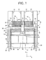
- Fig. 1 is a plan view of an electric-component (EC) mounting system to which the present invention is applied.
- the present EC mounting system includes a base 10; and a board conveyor 12, two EC supplying devices 16 and an EC mounting device 18 which are provided on the base 10.
- the board conveyor 12 conveys a printed wiring board 14 as a circuit substrate, and positions and supports the board 14 at a predetermined EC-mount station.
- the board conveyor 12 also functions as a circuit-substrate supporting device.
- Each of the two EC supplying devices 16 includes a feeder table 20, and a plurality of EC feeders 19 which are detachably attached to the feeder table 20 such that respective EC-supply portions of the feeders 19 are arranged along a straight line parallel to an X-axis direction.
- Each of the EC feeders 19 stores a number of electric components (ECs) of one sort, and supplies the ECs, one by one, from the EC-supply portion thereof.
- Each of the two feeder tables 20 is movable, while being guided by a pair of guide rails 22, between an EC-supply position and a retracted position in a Y-axis direction perpendicular to the X-axis direction.
- the EC mounting device 18 includes an X-Y moving device, which includes four columns 26 which stand on the base 10; two guide rails 28 which are horizontally supported by the columns 26 such that the guide rails 28 extend parallel to the Y-axis direction; two feed screws 30; two Y-axis motors (servomotors) 32; a Y-axis slide 40 which is provided with two nuts (not shown) threadedly engaged with the two feed screws 30, respectively, and is moved in the Y-axis direction by the screws 30 and the motors 32 while being guided by the guide rails 28; a feed screw 36; an X-axis motor (servomotor) 38; and an X-axis slide 40 which is provided, together with the feed screw 36 and the X-axis motor 38, on the Y-axis slide 40 and is moved in the X-axis direction by the screw 36 and the motor 38.
- X-Y moving device which includes four columns 26 which stand on the base 10; two guide rails 28 which are horizontally supported by the columns 26
- the X-axis slide 40 supports an EC holding head 44 which receives an EC 134 (Fig. 2) from an appropriate one of the two EC supplying devices 16, and conveys the EC 134 to a position above the printed board 14 positioned and supported by the board conveyor 12, along an EC-convey path below which an image taking device 48 including a line image sensor 46 is provided.
- an EC holding head 44 which receives an EC 134 (Fig. 2) from an appropriate one of the two EC supplying devices 16, and conveys the EC 134 to a position above the printed board 14 positioned and supported by the board conveyor 12, along an EC-convey path below which an image taking device 48 including a line image sensor 46 is provided.
- the EC holding head 44 includes an elevator member 50, as a main member thereof, that is supported by the X-axis slide 40 such that the elevator member 50 is movable upward and downward.
- the elevator member 50 is moved up and down by a feed screw 54 and a Z-axis motor (servomotor; Fig. 8) 56 while being guided by a pair of guide rails 52 provided on the X-axis slide 40.
- Reference numeral 58 designates a timing pulley as a transmitting device which transmits the rotation of the Z-axis motor 56 to the feed screw 54.
- the elevator member 50 supports a rotatable shaft 62 via bearings 60 such that the rotatable shaft 62 is rotatable about a vertical axis line thereof relative to the elevator member 50 and is not movable in directions parallel to the axis line relative to the same 50.
- the rotatable shaft 62 is rotated by a ⁇ -axis motor (servomotor) 64 via a pinion 66 and a gear (scissors gear) 68.
- a main portion of the gear 68 is integral with a lower end portion of the rotatable shaft 62.
- a linear-motor-driven chuck 72 as an EC holder is detachably attached to the main portion of the gear 68. More specifically described, an attaching member 76 is fixed to the main portion of the gear 68 via two connecting rods 74, and a stator 82 of a linear motor 80 as a main member of the chuck 72 is detachably attached to the attaching member 76.
- the linear motor 80 is a linear DC brushless motor, and includes, in addition to the above-indicated stator 82, two moving members 84, 86, and two guide members 88 for guiding the moving members 84, 86 in directions parallel to a lengthwise direction of the stator 82.
- the stator 82 includes a main portion 90 which is formed of an aluminum alloy as a non-magnetic material, and a number of permanent magnets 92 which are fixed to the main portion 90.
- Each of the permanent magnets 92 has an elongate shape like a square bar, and one of opposite elongate side surfaces thereof has a north pole (N-pole) and the other long side surface has a south pole (S-pole).
- the main portion 90 supports the magnets 92 such that the N-poles and the S-poles are alternate with each other in the lengthwise direction of the stator 82.
- the N-pole and S-pole side surfaces of each magnet 92 somewhat project from opposite side surfaces of the main portion 90.
- the N-poles (or S-poles) on one of the opposite side surfaces of the main portion 90 and the N-poles (or S-poles) on the other side surface of the main portion 90 provide a zigzag pattern in a plan view.
- Each of the two moving members 84, 86 includes two iron cores 96 which face the opposite two side surfaces of the main portion 90 of the stator 82, respectively. Respective lower end portions of the two cores 96 are connected to each other by a connecting table 98. Thus, each of the moving members 84, 86 has a generally U-shaped cross section. A U-phase coil, a V-phase coil, and a W-phase coil are wound around each core 96 to provide a coil unit.
- Each of the two coil units is designed such that under control of an electric current supplied to a corresponding one of the two moving members 84, 86, the each coil unit produces a force to linearly move the one moving member 84, 86 along the stator 82 owing to the interaction between the magnetic force produced by the each coil and the respective magnetic forces of the permanent magnets 92 of the stator 82.
- the respective movements of the two moving members 84, 86 are guided by the two guide members 88 fixed to the opposite side surfaces of the main portion 90 of the stator 82.
- Two sliders 100 are fixed to opposed inner surfaces of each of the U-shaped moving members 84, 86, respectively, and are engaged with the two guide members 88, respectively, via balls (not shown).
- each of the moving members 84, 86 is lightly moved along the guide members 88.
- Respective origin positions of the two moving members 84, 86 correspond to respective lengthwise opposite ends of the stator 82.
- Two origin sensors 102, 103 detect that the two moving members 84, 86 are positioned, or not positioned, at their origin positions, respectively.
- Two position sensors 104, 106 detect respective positions of the two moving members 84, 86 as respective distances thereof as measured from the respective origin positions.
- each of the origin sensors 102, 103 is provided by a transmission-type photoelectric sensor which includes a light emitting diode (LED) as a light emitter; a light receiver or detector for detecting a light emitted by the LED; and a shielding member which is provided on a corresponding one of the moving members 84, 86 and which shields, when the one moving member 84, 86 is positioned at its origin position, the light emitted by the LED and prevents the light from being detected by the light detector.
- the transmission-type photoelectric sensor may be replaced with a different sort of sensor, such as a reflection-type photoelectric sensor, a contact-type switch (e.g., a limit switch), or a proximity switch.
- each of the position sensors 104, 106 is provided by a magnetic linear scale (“Magnescale”) including a magnetic scale having magnetic graduations and a magnetic-field detecting head which is moved on the magnetic scale while producing an electric signal indicating the current position of a corresponding one of the moving members 84, 86.
- Magnetic scale may be replaced with an optical linear scale or a different sort of position sensor.
- the two position sensors 104, 106 may employ a single common magnetic scale.
- a pair of holding jaws 108, 109 which cooperate with each other to sandwich and hold the EC 134 are detachably attached to the respective tables 98 of the two moving members 84, 86.
- a jaw storing device 115 (Fig. 1) stores a plurality of holding jaws 108, 109 of different sorts.
- the current pair of jaws 108, 109 can be replaced with a pair of jaws 108, 109 of a different sort, depending upon the sort of new ECs to be mounted by the EC holding head 44.
- Fig. 1 stores a plurality of holding jaws 108, 109 of different sorts.
- the current pair of jaws 108, 109 can be replaced with a pair of jaws 108, 109 of a different sort, depending upon the sort of new ECs to be mounted by the EC holding head 44.
- each of the two tables 98 supports an attaching member 110 and a positioning pin 111
- each of the holding jaws 108, 109 includes a tapered shank 112 having an annular groove 113.
- two arm portions of a U-shaped holding spring 114 supported by the attaching member 110, elastically engage the annular groove 113 of the tapered shank 112.
- each jaw 108, 109 is prevented from coming off the attaching member 110.
- each jaw 108, 109 fits in a positioning recess formed in each jaw 108, 109, thereby preventing each jaw 108, 109 from being rotated about its tapered shank 112.
- each jaw 108, 109 is secured to the corresponding moving member 84, 86, such that the each jaw 108, 109 is not movable relative to the corresponding moving member 84, 86.
- the present EC mounting system automatically replaces the current pair of holding jaws 108, 109 with another pair of holding jaws 108, 109 which are stored in the jaw storing device 115, which is provided between the EC supplying devices 16 and the board conveyor 12, as shown in Fig. 1.
- the replacement of the current jaws 108, 109 is needed, first, the EC holding head 44 is moved to a position above the jaw storing device 115, then the chuck 72 is moved down toward the device 115, subsequently a movable member of the device 115 is moved and engaged with the current jaws 108, 109, and the chuck 72 is moved up, so that the current jaws 108, 109 are removed from the chuck 72 and are stored in the device 115.
- each jaw 108, 109 can be attached to, and detached from, the attaching member 110 by just applying a force greater than a threshold value, to the each jaw 108, 109 in an axial direction of the tapered shank 112 thereof.
- the current jaws 108, 109 can be easily exchanged with different jaws 108, 109.
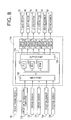
- the present EC mounting system is controlled by a control device 116 shown in Fig. 8.
- Fig. 8 shows only portions of the EC mounting system that are relevant to the present invention.
- the control device 116 is essentially provided by a computer 118 including a processing unit (PU) 120, a read only memory (ROM) 122, a random access memory (RAM) 124, an input port 126, an output port 128, and a bus line for connecting those elements 120, 122, 124, 126, 128 to one another.
- An image-data processing computer 130 which processes image data representing the image taken by the image taking device 48, is connected to the input port 126.
- the origin sensors 102, 103, the position sensors 104, 106, other sensors, and other computers are also connected to the input port 126.
- the output port 128 is connected via respective drive circuits to the Y-axis motors 32, the X-axis motor 38, the Z-axis motor 56, the ⁇ -axis motor 64, and the two moving members 84, 86 of the chuck 72.
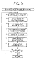
- the ROM 122 stores various control programs including an electric-circuit assembling routine represented by the flow charts shown in Figs. 9 to 11. According to the electric-circuit assembling routine, the control device 116 controls the EC mounting system to automatically mount the ECs 134 on the printed wiring board 14 and thereby assemble an electric-circuit board 14.
- the electric-circuit assembling operation which is carried out by the present EC mounting system.
- Step S1 the control device 116 starts with Step S1 to read out, from the RAM 124, control data relating to a current EC 134 which is to be mounted next on the printed board 14.
- This control data include identification (ID) data identifying the sort of current EC, a take-out position where the EC holding head 44 or the chuck 72 takes out the current EC 134 of that sort from one of the EC feeders 19 of the EC supplying devices 16, and a mount position where the chuck 72 mounts the current EC 134 on the printed board 14.
- ID identification
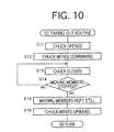
- Step S1 is followed by Step S2 where the control device 116 moves the chuck 72 to the take-out position, and then by Step S3 where the control device 116 carries out an EC taking-out routine represented by the flow chart of Fig. 10.
- the control device 116 opens the chuck 72. More specifically described, the control device 116 reads out, based on the ID data identifying the sort of current EC 134, distance data indicating respective prescribed distances of respective portions of the EC 134 that are to be held by the two holding jaws 108, 109, from a reference position, i.e., the centerline of the chuck 72.
- control device 116 opens each of the two moving members 84, 86 to position a corresponding one of the two holding jaws 108, 109 at a position which is more distant from the reference position than a corresponding one of the read-out prescribed distances by a predetermined distance.
- the reference position i.e., the centerline of the chuck 72 coincides with the axis line of rotation of the rotary shaft 62 in the state in which the chuck 72 is attached to the attaching member 76.
- the EC 134 is one which has a plane-symmetric shape with respect to at least a first plane perpendicularly intersecting the direction in which the two holding jaws 108, 109 are moved toward, and away from, each other, the two jaws 108, 109 of the chuck 72 are opened symmetrically with respect to a second plane including the axis line of rotation of the rotatable shaft 62.
- a portion of the control device 116 that carries out Step S11 provides an object-dependent control portion.
- the same portion of the control device 116 provides a symmetric-movement control portion in the case where the EC 134 is plane-symmetric, and provides an asymmetric-movement control portion in the case where the EC 134 is asymmetric.
- Step S12 the control device 116 controls the Z-axis motor 56 to move the elevator member 56 downward to a height position where the chuck 72 can hold the current EC 134.
- Step S12 is followed by Steps S13 to S16 to close the chuck 72 and thereby hold the EC 134.
- the EC 134 indicated at two-dot chain line in Fig. 3 is the thinnest one of a plurality of sorts of ECs which can be held by the chuck 72. Since the chuck 72 can be largely opened, the chuck 72 can hold an EC having a thickness equal to more than several times the thickness of the EC 134.
- the EC 134 can have, in a direction perpendicular to the direction in which the EC 134 is held by the chuck 72, such a dimension as indicated at two-dot chain line in Fig. 2. Since the elevator member 50 or the chuck 72 can be largely elevated and lowered, the EC 134 is allowed to have a height (i.e., a vertical dimension) which can change in a wide range.
- the current EC 134 is fed to, and positioned at, a prescribed position by one of the EC feeders 19 of the EC supplying devices 16. Therefore, in a state in which the chuck 72 being opened has been moved down, the two holding jaws 108, 109 are horizontally distant from respective outer surfaces of the EC 134 by respective small distances equal to each other. Then, the chuck 72 is closed by moving the two moving members 84, 86 at respective speeds equal to each other. When the two holding jaws 108, 109 contact the respective outer surfaces of the EC 134, the moving members 84, 86 are stopped because they cannot be moved any more.
- the holding force with which the two jaws 108, 109 hold the EC 134 is controlled at an appropriate force by the control device 116 by controlling, based on the ID data indicating the sort of current EC 134 read out at Step S1, the respective electric currents supplied to the respective coil units of the two moving members 84, 86.
- the above appropriate force is appropriate for the current EC 134 in the meaning that that force is not so great as to break the EC 134 or so small as to fail to hold the same 134. If the two moving members 84, 86 are thus stopped, a positive judgment is made at Step S14, and the control goes to Step S15 to keep still the two moving members 84, 86.
- control device 116 controls the respective electric currents supplied to the respective coil units of the two moving members 84, 86, such that the two holding jaws 108, 109 hold the EC 134 with the appropriate force and such that the two moving members 84, 86 are not moved from the respective stopped positions. For example, if the first member 84 applies, to the EC 134, a force somewhat greater than that applied by the second member 86, then the two members 84, 86 holding the EC 134 move rightward in Fig. 3, which is detected by the position sensors 104, 106.
- the control device 116 decreases the electric current supplied to the coil unit of the first moving member 84, or increases the electric current supplied to the coil unit of the second moving member 86, so that the two members 84, 86 holding the EC 134 are moved leftward. Whether the control device 116 should decrease the first current supplied to the first member 84 or increase the second current supplied to the second member 86 depends on which one of decreasing the first current or increasing the second current is more appropriate for producing the appropriate holding force. In this way, the control device 116 controls the two moving members 84, 86 to hold the EC 34 with the appropriate holding force and to be kept still at the respective stopped positions. In this state, the control device 116 carries out Step S16 to move the chuck 72 upward and thus take out the EC 134 from the EC supplying devices 16.
- the control of the control device 116 goes to Step S4 to move the chuck 72 to an image-take-start position, and then to Step S5 to control the image taking device 48 to take an image of the EC 134 held by the chuck 72.
- the image taking device 48 includes the line-image sensor 46 which includes an array of CCDs (charge coupled devices). Therefore, when the chuck 72 is moved at a prescribed speed from the image-take-start position in the Y-axis direction, the line-image sensor 46 iteratively takes respective line images of the EC 134 at respective predetermined intervals of time, so that image data representing an image of the entirety of EC 134 as a group of the line images are obtained by the image taking device 48.
- the image-data processing computer 130 compares the thus obtained image data with correct image data, pre-stored in the RAM 124, representing a correct image of EC 134 which is correctly held by the chuck 72, i.e., at respective correct positions in the X-axis and Y-axis directions and at a correct angular phase (or rotation position) about the Z-axis direction.
- the computer 130 calculates respective positional errors, ⁇ X, ⁇ Y, of a reference position of the EC 134 from the respective correct positions in the X-axis and Y-axis directions, and an angular-phase error, ⁇ ⁇ , of the EC 134 about a straight line which passes through the reference position, parallel to the Z-axis direction, i.e., perpendicularly to the X-axis and Y-axis directions.
- the image-data processing computer 130 supplies error data representing the thus calculated errors ⁇ X, ⁇ Y, ⁇ ⁇ to the control device 116 or the computer 118.
- the control device 116 moves the chuck 72 to the mount position indicated by the control data read out at Step S1.
- the image-data processing computer 130 supplies the error data representing the errors ⁇ X, ⁇ Y, ⁇ ⁇ to the control device 116. Consequently the control device 116 stops the chuck 72 at respective X-axis-direction and Y-axis-direction positions and an angular phase which have been obtained by modifying, by the errors ⁇ X, ⁇ Y, ⁇ ⁇ , the correct or nominal X-axis-direction and Y-axis- direction positions and the correct angular phase.
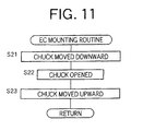
- Step S6 is followed by Step S7 to carry out an EC mounting routine represented by the flow chart of Fig. 11.
- the control device 116 moves the chuck 72 downward to press the EC 134 against the printed wiring board 14 and temporarily fix the same 134 with an adhesive which has already been applied to the board 14.
- Step S21 is followed by Step S22 to open the chuck 72, and then by Step S23 to move the chuck 72 upward.
- Step S8 of Fig. 9 the control device 116 repeats Step S1 and the following steps. Meanwhile, if a positive judgment is made at Step S8, the current control cycle according to the electric-circuit assembling routine of Fig. 9 is finished.
- the linear-motor-driven chuck 72 includes the two holding jaws 108, 109 for sandwiching the EC 134 in one direction and thereby holding the same 134.
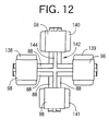
- the chuck 72 may be replaced by a different linear-motor-driven chuck 142 shown in Fig. 12.
- the chuck 142 includes two linear motors 80 including four moving members 138, 139, 140, 141, two 138, 139 of which are moved toward, and away from, each other in a first direction, the other two 140, 141 of which are moved toward, and away from, each other in a second direction perpendicular to the first direction, and all of which cooperate with one another to hold an EC.
- the two linear motors include a common stator 144 having four arm portions which extend radially outward and are equiangularly spaced from one another about a vertical centerline of the chuck 142. Since the four moving members 138-141 may interfere with one another around the centerline of the chuck 142, the shapes and sizes of ECs that can be held by the chuck 142 are somewhat limited. However, in the case where each of the four moving members 138-141 has a shape overhanging or projecting toward the centerline, the chuck 142 can hold even an EC having a small size.
- Two pairs of holding jaws 108, 109 are detachably attached to the two pairs of moving members 138-141, respectively.
- each of the four jaws 108, 109 be supported by a corresponding one of the four moving members 128-141, such that the each jaw 108, 109 is movable relative to the one moving member 138-141 in directions perpendicular to the directions in which the each jaw is moved with the one moving member, and be biased by a biasing member such that the each jaw is normally biased toward a neural position thereof.
- the above-described attaching member 110 is attached to each of the four tables 98 of the chuck 142, such that the attaching member 110 is movable, owing to a stepped screw and an elongate hole, relative to the each table 98 in the directions perpendicular to the directions in which the corresponding pair of holding jaws 108, 109 are opened and closed, and a spring member as the biasing member biases the attaching member 110 toward its neutral position.
- each of respective positions of the EC relative to the chuck 142 in the first and second directions may be changed or adjusted by moving a corresponding one or ones of the four moving members 138-141 relative to the stator 144.
- control device 116 controls the respective electric currents supplied to the respective coil units of the two moving members 84, 86 or the four moving members 138-141, so that the two or four holding jaws 108, 109 hold an EC with a holding force suitable for the sort of EC while being kept still at the respective stopped positions.
- control device 116 may be so modified as to control the respective positions of the two or four moving members 84, 86, 138-141 in such a manner that the two or four holding jaws 180, 109 are kept still at respective positions where the jaws 108, 109 first contact an EC.
- linear motors 80
- linear stators 82; 144
- moving members 84, 86; 138-141
- guide members 88
- holding members 108, 109
Landscapes
- Engineering & Computer Science (AREA)
- Manufacturing & Machinery (AREA)
- Microelectronics & Electronic Packaging (AREA)
- Supply And Installment Of Electrical Components (AREA)
- Manipulator (AREA)
Applications Claiming Priority (2)
| Application Number | Priority Date | Filing Date | Title |
|---|---|---|---|
| JP2000004637 | 2000-01-13 | ||
| JP2000004637A JP2001198873A (ja) | 2000-01-13 | 2000-01-13 | リニアモータチャックおよび電気部品装着システム |
Publications (2)
| Publication Number | Publication Date |
|---|---|
| EP1117286A2 true EP1117286A2 (de) | 2001-07-18 |
| EP1117286A3 EP1117286A3 (de) | 2004-01-02 |
Family
ID=18533399
Family Applications (1)
| Application Number | Title | Priority Date | Filing Date |
|---|---|---|---|
| EP01300161A Withdrawn EP1117286A3 (de) | 2000-01-13 | 2001-01-09 | Spindel und Bestückungsvorrichtung für elektrische Bauteile |
Country Status (3)
| Country | Link |
|---|---|
| US (1) | US6493927B2 (de) |
| EP (1) | EP1117286A3 (de) |
| JP (1) | JP2001198873A (de) |
Cited By (1)
| Publication number | Priority date | Publication date | Assignee | Title |
|---|---|---|---|---|
| EP1536677A4 (de) * | 2002-07-19 | 2006-11-15 | Matsushita Electric Industrial Co Ltd | Teileeinf gekopfeinrichtung, teileeinf geeinrichtung und teileeinf geverfahren |
Families Citing this family (11)
| Publication number | Priority date | Publication date | Assignee | Title |
|---|---|---|---|---|
| DE60001304T2 (de) * | 2000-05-23 | 2003-11-27 | Lns S.A., Orvin | Stangenzuführvorrichtung |
| JP2002200585A (ja) * | 2000-12-28 | 2002-07-16 | Fuji Mach Mfg Co Ltd | 電気部品保持装置 |
| JP4541601B2 (ja) * | 2001-07-19 | 2010-09-08 | 富士機械製造株式会社 | 電動チャックを用いた電気部品装着システム |
| JP4888638B2 (ja) * | 2005-12-22 | 2012-02-29 | 日本パルスモーター株式会社 | クランプ機構としての複合直動装置 |
| US8310961B2 (en) * | 2007-10-08 | 2012-11-13 | Nokia Siemens Networks Oy | Techniques for link utilization for half-duplex and full-duplex stations in a wireless network |
| DE102009037586A1 (de) * | 2009-08-14 | 2011-02-17 | Weiß GmbH Sondermaschinentechnik | Greifvorrichtung |
| KR200460019Y1 (ko) * | 2009-10-29 | 2012-04-27 | (주)티에스이 | 픽앤플레이스 시스템 |
| JP5787436B2 (ja) * | 2011-03-07 | 2015-09-30 | 株式会社 弘 前 機 械 開 発 | プレパラート用グリッパーヘッド |
| JP6385408B2 (ja) * | 2016-09-29 | 2018-09-05 | 平田機工株式会社 | 移載ユニット、移載装置および保持ユニット |
| US12250775B2 (en) * | 2019-10-03 | 2025-03-11 | Yamaha Hatsudoki Kabushiki Kaisha | Rotary mounting head and component mounting machine |
| US20250170706A1 (en) * | 2022-03-01 | 2025-05-29 | Kyocera Corporation | Robot hand system, control method, robot hand, and control device |
Family Cites Families (6)
| Publication number | Priority date | Publication date | Assignee | Title |
|---|---|---|---|---|
| US4680523A (en) * | 1986-03-13 | 1987-07-14 | Lord Corporation | Apparatus and method for handling articles in automated assembly processes |
| NL8701139A (nl) * | 1987-05-13 | 1988-12-01 | Philips Nv | Geleideinrichting. |
| US4833776A (en) * | 1988-01-29 | 1989-05-30 | Westinghouse Electric Corp. | Tactile retrieval and insertion and method for electronic components in through-hole printed circuit boards |
| JPH0693559A (ja) | 1992-05-21 | 1994-04-05 | Kanebo Ltd | アセテート系繊維製品の収縮加工法 |
| JP2000230618A (ja) * | 1999-02-10 | 2000-08-22 | Thk Co Ltd | 防塵型案内装置 |
| JP2001105332A (ja) * | 1999-10-01 | 2001-04-17 | Smc Corp | 電動クランプ装置 |
-
2000
- 2000-01-13 JP JP2000004637A patent/JP2001198873A/ja active Pending
- 2000-12-26 US US09/745,442 patent/US6493927B2/en not_active Expired - Lifetime
-
2001
- 2001-01-09 EP EP01300161A patent/EP1117286A3/de not_active Withdrawn
Cited By (2)
| Publication number | Priority date | Publication date | Assignee | Title |
|---|---|---|---|---|
| EP1536677A4 (de) * | 2002-07-19 | 2006-11-15 | Matsushita Electric Industrial Co Ltd | Teileeinf gekopfeinrichtung, teileeinf geeinrichtung und teileeinf geverfahren |
| US7568284B2 (en) | 2002-07-19 | 2009-08-04 | Panasonic Corporation | Components insertion method |
Also Published As
| Publication number | Publication date |
|---|---|
| JP2001198873A (ja) | 2001-07-24 |
| US20010008326A1 (en) | 2001-07-19 |
| US6493927B2 (en) | 2002-12-17 |
| EP1117286A3 (de) | 2004-01-02 |
Similar Documents
| Publication | Publication Date | Title |
|---|---|---|
| US7278204B2 (en) | Electric-component holding apparatus | |
| KR100311747B1 (ko) | 표면실장기의 인쇄회로기판 이송장치 | |
| CA1240403A (en) | Electronic component mounting system | |
| US6973714B2 (en) | Electrically operated chucking apparatus | |
| US6493927B2 (en) | Linear-motor-driven chuck and electric-component mounting system | |
| US7102148B2 (en) | Calibration method and device in electronic component mounting apparatus | |
| EP0637199B1 (de) | Automatische Bestückungseintichtung für elektronische Teile | |
| US7966718B2 (en) | Substrate-related-operation performing apparatus and substrate-related-operation performing system | |
| US6941646B2 (en) | Electric-component mounting system | |
| US6718626B2 (en) | Apparatus for detecting positioning error of a component with respect to a suction nozzle | |
| US20030209679A1 (en) | Method and program for obtaining positioning errors of printed-wiring board, and electronic-circuit-component mounting system | |
| US8823791B2 (en) | Component recognizing device, surface mounting machine, and component testing machine | |
| US7181089B2 (en) | Method and apparatus for searching for fiducial marks, and method of detecting positions of the fiducial marks | |
| GB2246211A (en) | Electronic component mounting apparatus | |
| KR20050023424A (ko) | 반송용 로봇 시스템 및 반송용 로봇의 제어 방법 | |
| KR101355041B1 (ko) | 회전 각도 검출 장치, 회전 각도 검출 방법, 및 부품 실장 장치 | |
| KR20200021539A (ko) | 제1 물체를 제2 물체에 대하여 위치 결정하는 장치 및 방법 | |
| US20020040519A1 (en) | Method of detecting position of printed-wiring board, and method and system for effecting working operation on the board, using detected board position | |
| EP0809926B1 (de) | Bestückungsautomat für bauelemente | |
| CN110854421B (zh) | 一种电芯和外壳的入壳装置 | |
| CN209503415U (zh) | 位置调整机构及定位装置 | |
| JPS6218087A (ja) | 電子部品の自動実装装置 | |
| WO2023084083A1 (en) | Component placement systems, multi-pipette placement heads, and methods of using the same | |
| KR100406058B1 (ko) | 테이프피더의 픽업센터 감지방법 | |
| JP2002368492A (ja) | 電気部品装着方法および電気部品装着システム |
Legal Events
| Date | Code | Title | Description |
|---|---|---|---|
| PUAI | Public reference made under article 153(3) epc to a published international application that has entered the european phase |
Free format text: ORIGINAL CODE: 0009012 |
|
| AK | Designated contracting states |
Kind code of ref document: A2 Designated state(s): AT BE CH CY DE DK ES FI FR GB GR IE IT LI LU MC NL PT SE TR |
|
| AX | Request for extension of the european patent |
Free format text: AL;LT;LV;MK;RO;SI |
|
| PUAL | Search report despatched |
Free format text: ORIGINAL CODE: 0009013 |
|
| AK | Designated contracting states |
Kind code of ref document: A3 Designated state(s): AT BE CH CY DE DK ES FI FR GB GR IE IT LI LU MC NL PT SE TR |
|
| AX | Request for extension of the european patent |
Extension state: AL LT LV MK RO SI |
|
| 17P | Request for examination filed |
Effective date: 20031124 |
|
| AKX | Designation fees paid |
Designated state(s): DE FR GB IT NL |
|
| 17Q | First examination report despatched |
Effective date: 20080317 |
|
| STAA | Information on the status of an ep patent application or granted ep patent |
Free format text: STATUS: THE APPLICATION IS DEEMED TO BE WITHDRAWN |
|
| 18D | Application deemed to be withdrawn |
Effective date: 20080729 |