EP1117877B1 - Vorrichtung zum modulieren von durchflüssen - Google Patents
Vorrichtung zum modulieren von durchflüssen Download PDFInfo
- Publication number
- EP1117877B1 EP1117877B1 EP99945753A EP99945753A EP1117877B1 EP 1117877 B1 EP1117877 B1 EP 1117877B1 EP 99945753 A EP99945753 A EP 99945753A EP 99945753 A EP99945753 A EP 99945753A EP 1117877 B1 EP1117877 B1 EP 1117877B1
- Authority
- EP
- European Patent Office
- Prior art keywords
- fluid
- flow path
- conduit
- flow
- fluid flow
- Prior art date
- Legal status (The legal status is an assumption and is not a legal conclusion. Google has not performed a legal analysis and makes no representation as to the accuracy of the status listed.)
- Expired - Lifetime
Links
Images

Classifications
-
- E—FIXED CONSTRUCTIONS
- E04—BUILDING
- E04H—BUILDINGS OR LIKE STRUCTURES FOR PARTICULAR PURPOSES; SWIMMING OR SPLASH BATHS OR POOLS; MASTS; FENCING; TENTS OR CANOPIES, IN GENERAL
- E04H4/00—Swimming or splash baths or pools
- E04H4/12—Devices or arrangements for circulating water, i.e. devices for removal of polluted water, cleaning baths or for water treatment
Definitions
- the invention relates to an apparatus for modulating fluid flow according to the preamble of claim 1. More particularly, the invention relates to an apparatus for modulating fluid flow between a first fluid path and a second flow path which branches from the first flow path.
- US 4,816,155 discloses an apparatus for mixing a solid/liquid slurry and separating said liquid from said slurry, wherein said apparatus comprises a horizontal slurry pipe for carrying a flow of the slurry, a plurality of mixing elements each comprising a cylindrical tube, inserted completely through said slurry pipe at angles perpendicular to the slurry flow, wherein the mixing elements obstruct only a portion of the slurry flow, wherein drainage surfaces of each of the mixing elements comprise openings in the tubes allowing passage of the liquid, and preventing passage of said solid into the mixing elements. Furthermore, this apparatus comprises an exit port connected to a lower end of each of the mixing elements for enabling removal of the liquid from the mixing elements.
- US 5,474,102 discloses a fluid distribution manifold, where the input piping is inserted in through the manifold's circular intake opening and onto its cylindrical input port.
- the manifold's intake opening leads through a cylindrical path to a closed terminal end.
- Along the inner manifold wall there are arranged in a sequence, a number of distribution outlet openings and their respective ports.
- the invention provides apparatus for modulating fluid flow comprises a first flow path, a second flow path transverse to the first flow path, the second flow path having a fluid inlet which opens onto the first flow path whereby a portion of fluid flowing along the first flow path is diverted into the second flow path, the position of the fluid inlet being set in relation to the direction of fluid flow according to the extent of fluid to be diverted from the first flow path into the second flow path.
- the position of the fluid inlet is adjustable to vary the extent of fluid diverted as desired. Such adjustment may be made prior to and/or during operation of the apparatus.
- the fluid inlet comprise one or more apertures.
- the fluid inlet comprises two apertures circumferentially spaced about the conduit.
- the first flow path is defined by a conduit having an internal size greater than the external size of the conduit defining the second flow path.
- the invention has been devised particularly, although not solely, for use in a fluid distribution manifold having a plurality of branch outlets, the arrangement allowing fluid discharging from the manifold through the branch outlets to be regulated.
- the regulation allows a uniform fluid flow through each of the branch outlets.
- a conventional manifold having a plurality of branch outlets does not provide an even distribution of fluid flowing through the various branch outlets.
- a particular application of the apparatus according to the invention is In a horizontal swimming pool falter.
- a horizontal swimming pool filter typically has an inlet manifold positioned above a filtering media, the purpose of the manifold being to distribute water to be filtered evenly within a water space above the filtering media, so as to allow a laminar flow which does not disturb the surface of the filtering media bed. Uneven distribution of water would cause currents in the water space above the filtering media bed, causing scouring in the surface of the filtering media which in turn causes the filtering media to migrate, leaving areas of reduced media depth.
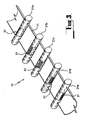
- the embodiments shown in the drawings are each directed to a manifold for use in a horizontal swimming pool filter, the manifold being provided to distribute pool water evenly into a water space above a bed of filtering media contained within the filter.
- the manifold 10 comprises a first conduit 11 defining a first flow passage 13.
- the conduit 11 is cylindrical and closed at one end by way of a cap 15. Pool water to be filtered is delivered to the flow passage 13 through the other end of the conduit 11.
- the manifold 10 further includes a plurality of branch lines 19.
- the branch lines 19 are in pairs on opposed sides of the first conduit 11, each pair of branch lines 19 being defined by a second conduit 21 extending transversely through the first conduit 11.
- Each second conduit 21 is received within holes 23 formed in the cylindrical side wall of the first conduit 11.
- Each second conduit 21 has an external diameter which is less than the interior diameter of the first conduit 11.
- the second conduits do not block flow along the first flow passage 13.
- the second conduits 21 do, however, act as baffles in the first flow passage 13.
- Each conduit 21 has a fluid inlet 31 opening into the interior of the first flow passage. With this arrangement, some of the fluid within the first flow passage can be diverted into the second conduit through the fluid inlet 31. The diverted fluid then flows along the two branch lines 19 defined by the respective second conduit 21.
- each second conduit 21 The extent to which fluid is diverted from the first conduit 11 into each second conduit 21 can be regulated by the orientation of the inlet 31 with respect to the first conduit.
- the fluid inlets 31 in the five second conduits shown in the drawings can be so positioned that the volumetric flow rate of fluid through each of the branch lines 19 is approximately equal.
- the fluid inlets 31 in the second conduits 21 have a range of positions including a position which directly faces the fluid flow in the first conduit, a position which faces a direction generally normal to the fluid flow and a position which faces a direction opposite to the fluid flow.
- the various second conduits 21 are rotated within the first conduit 11 so that the respective inlets 31 assume the required position and then the second conduits 21 are sealingly fixed in position within the first conduit 11.
- the fixing can be achieved in any suitable fashion such as by adhesive bonding or welding.
- each fluid inlet 31 in each second conduit 21 is defined by a single aperture in the cylindrical side wall of the conduit.
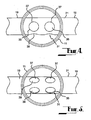
- each fluid inlet 31 comprises a plurality of apertures 35 in the cylindrical side wall of the respective second conduit 21.
- the apertures 35 are in pairs 37, with the two apertures 39 in each pair being circumferentially spaced with respect to each other. The circumferential spacing is such that the centres of the apertures 39 in each pair 37 are approximately at 90° with respect to each other.
- the second conduit is shown in an orientation in which one aperture 39 of each pair is directly facing the direction of fluid flow and the other aperture 39 of each pair is facing a direction generally normal to the direction of fluid flow.
- the second conduit 21 is shown in an orientation in which the apertures 39 in each pair 37 obliquely face the direction of fluid flow.
- the apparatus can be operated in a reverse flow mode in which fluid enters the manifold 10 through the branch lines 19 and exits through the first conduit 11.
- the fluid inlets 31 can produce a venturi effect in the manifold.
- the present invention provides a simple yet highly effectively apparatus for modulating fluid flow.
- the apparatus according to the invention has application for fluid flows other than pool water. Indeed, the apparatus may have application for modulating flow of any liquid or gaseous fluid (or combination thereof).
Landscapes
- Engineering & Computer Science (AREA)
- Architecture (AREA)
- Water Supply & Treatment (AREA)
- Civil Engineering (AREA)
- Structural Engineering (AREA)
- Pipe Accessories (AREA)
- Feeding, Discharge, Calcimining, Fusing, And Gas-Generation Devices (AREA)
- Paper (AREA)
- External Artificial Organs (AREA)
- Filtration Of Liquid (AREA)
- Transplanting Machines (AREA)
- Interface Circuits In Exchanges (AREA)
- Gyroscopes (AREA)
Claims (4)
- Vorrichtung (10) zum Modulieren einer Fluidströmung umfassend- einen ersten Strömungsweg (13) und- einen zweiten Strömungsweg (19), der quer zu dem ersten Strömungsweg (13) verläuft,wobei der zweite Strömungsweg (19) von einer Leitung (21) gebildet wird, die sich quer durch den ersten Strömungsweg (13) erstreckt, aber die Fluidströmung längs diesem nicht vollständig blockiert,
wobei die Leitung (21) einen Fluideinlass (31) aufweist, der in den ersten Strömungsweg (13) mündet, wodurch ein Teil des längs des ersten Strömungswegs (13) strömenden Fluids in den zweiten Strömungsweg (19) umgeleitet wird,
wobei die Position des Fluideinlasses (31) zum Variieren der Menge des umzuleitenden Fluids zwischen einer ersten und einer zweiten Position einstellbar ist, wobei die erste Position bezüglich der Richtung der Fluidströmung in dem ersten Strömungsweg (13) stromaufwärts und die zweite Position bezüglich der Richtung der Fluidströmung in dem ersten Strömungsweg (13) stromabwärts liegt,
dadurch gekennzeichnet, dass die Leitung (21) zwei Abzweigleitungen bereitstellt, die sich von entgegengesetzten Seiten des ersten Strömungswegs (13) erstrecken. - Vorrichtung zum Modulieren einer Fluidströmung nach Anspruch 1, dadurch gekennzeichnet, dass die Position des Einlasses (31) auf eine bestimmte Position zwischen der ersten und zweiten Position eingestellt und in Bezug auf die Richtung der Fluidströmung in dem ersten Strömungsweg (13) fixiert wird, nachdem er in der bestimmten Position platziert worden ist.
- Vorrichtung zum Modulieren einer Fluidströmung nach Anspruch 1, dadurch gekennzeichnet, dass der Fluideinlass (31) sich in einer Seitenwand der Leitung (21) befindet.
- Vorrichtung zum Modulieren einer Fluidströmung nach Anspruch 3, dadurch gekennzeichnet, dass die Leitung (21) einen kreisförmigen Querschnitt hat, so dass sich der Fluideinlass (31) in der zylindrischen Seitenwand der Leitung (21) befindet.
Applications Claiming Priority (3)
| Application Number | Priority Date | Filing Date | Title |
|---|---|---|---|
| AUPP5684A AUPP568498A0 (en) | 1998-09-03 | 1998-09-03 | Apparatus for modulating fluid flow |
| AUPP568498 | 1998-09-03 | ||
| PCT/AU1999/000719 WO2000014344A1 (en) | 1998-09-03 | 1999-09-03 | Apparatus for modulating fluid flow |
Publications (3)
| Publication Number | Publication Date |
|---|---|
| EP1117877A1 EP1117877A1 (de) | 2001-07-25 |
| EP1117877A4 EP1117877A4 (de) | 2004-12-29 |
| EP1117877B1 true EP1117877B1 (de) | 2009-08-19 |
Family
ID=3809908
Family Applications (1)
| Application Number | Title | Priority Date | Filing Date |
|---|---|---|---|
| EP99945753A Expired - Lifetime EP1117877B1 (de) | 1998-09-03 | 1999-09-03 | Vorrichtung zum modulieren von durchflüssen |
Country Status (6)
| Country | Link |
|---|---|
| EP (1) | EP1117877B1 (de) |
| AT (1) | ATE440185T1 (de) |
| AU (2) | AUPP568498A0 (de) |
| DE (1) | DE69941295D1 (de) |
| ES (1) | ES2330172T3 (de) |
| WO (1) | WO2000014344A1 (de) |
Family Cites Families (13)
| Publication number | Priority date | Publication date | Assignee | Title |
|---|---|---|---|---|
| GB137461A (en) * | 1919-05-13 | 1920-01-15 | Spensers Ltd | Attaching gas brackets |
| GB272673A (en) * | 1926-06-07 | 1927-06-23 | Eugene Frank Delery | Improvements in distribution systems |
| DE2600562C3 (de) * | 1976-01-09 | 1980-05-08 | Chemische Fabrik Pfersee Gmbh, 8900 Augsburg | Verfahren zur waschbeständigen FUzfreiausriistung von WoIl- und wollhaltigen Textilien |
| DE2600572C3 (de) * | 1976-01-09 | 1982-02-11 | Lang Apparatebau Gmbh, 8221 Siegsdorf | Vorrichtung zum Dosieren von Chemikalienlösungen |
| US4331174A (en) * | 1978-11-06 | 1982-05-25 | Durance, Inc. | Inline dispersal valve |
| EP0128690B1 (de) * | 1983-05-26 | 1989-12-20 | Spiro Machines S.A. | Durchflussregelventile für Fluide |
| SU1608620A1 (ru) * | 1986-05-11 | 1990-11-23 | Предприятие П/Я В-2804 | Регул тор расхода |
| US4816155A (en) * | 1986-07-14 | 1989-03-28 | Klr Machines, Inc. | Juice drainage system |
| US5474102A (en) * | 1991-07-15 | 1995-12-12 | Lopez; Robert | Fluid distribution manifold |
| DE4324555A1 (de) * | 1993-07-22 | 1995-01-26 | Ingelheim Peter Graf Von | Einfache Regeleinrichtung zur Verstellung von Schiebern, Toren, Klappen, Drosseln und Ventilen für Strömungen und Kanäle oder Rohrleitungen für strömende Medien mit großer Querschnittsfläche |
| FR2710363A1 (fr) * | 1993-09-21 | 1995-03-31 | Roumagnac Max | Dispositif de branchement d'une tête de nettoyage par aspiration du fond d'une piscine à une bouche de refoulement de cette dernière. |
| US5596773A (en) * | 1995-08-09 | 1997-01-28 | Cueman; Ronald J. | Water level control device |
| US5795475A (en) * | 1996-07-12 | 1998-08-18 | Neoperl, Inc. | Coupler/diverter for counter-top RO filter |
-
1998
- 1998-09-03 AU AUPP5684A patent/AUPP568498A0/en not_active Abandoned
-
1999
- 1999-09-03 EP EP99945753A patent/EP1117877B1/de not_active Expired - Lifetime
- 1999-09-03 WO PCT/AU1999/000719 patent/WO2000014344A1/en not_active Ceased
- 1999-09-03 DE DE69941295T patent/DE69941295D1/de not_active Expired - Fee Related
- 1999-09-03 AT AT99945753T patent/ATE440185T1/de not_active IP Right Cessation
- 1999-09-03 ES ES99945753T patent/ES2330172T3/es not_active Expired - Lifetime
- 1999-09-03 AU AU58396/99A patent/AU743517B2/en not_active Expired
Also Published As
| Publication number | Publication date |
|---|---|
| ES2330172T3 (es) | 2009-12-04 |
| AU5839699A (en) | 2000-03-27 |
| DE69941295D1 (de) | 2009-10-01 |
| WO2000014344A1 (en) | 2000-03-16 |
| EP1117877A1 (de) | 2001-07-25 |
| EP1117877A4 (de) | 2004-12-29 |
| AUPP568498A0 (en) | 1998-10-01 |
| AU743517B2 (en) | 2002-01-24 |
| ATE440185T1 (de) | 2009-09-15 |
Similar Documents
| Publication | Publication Date | Title |
|---|---|---|
| US5354460A (en) | Fluid transfer system with uniform fluid distributor | |
| JP2007533451A5 (de) | ||
| US3936382A (en) | Fluid eductor | |
| JPH05208125A (ja) | 混合装置 | |
| CN113213681A (zh) | 净水系统 | |
| US20030192598A1 (en) | Apparatus for modulating fluid flow | |
| GB2319734A (en) | Injecting fluid additives into a gaseous or liquid stream | |
| EP3640509B1 (de) | Verteiler für eine flüssigkeit | |
| AU743517B2 (en) | Apparatus for modulating fluid flow | |
| WO2000069547A1 (en) | A fluid flow housing | |
| US8715500B2 (en) | Flow distributor plate for the treatment of water by reverse osmosis | |
| EP2056958A1 (de) | Verbesserungen von reaktionsgefässen oder in bezug auf sie | |
| CN219136463U (zh) | 滤芯组件和净水系统 | |
| CN215102597U (zh) | 净水系统 | |
| US11739004B2 (en) | Device for the purification of fluids, nozzle insert for ion exchange column, method of deionizing a fluid and use of such a device | |
| US3969241A (en) | Method of and apparatus for separating chemical solutions in membrane processes | |
| JP4110625B2 (ja) | 脱気モジュール | |
| AU679624B2 (en) | A device for the positioning of a throttle/mixing body | |
| JPH01121667A (ja) | 冷媒分流器 | |
| JPH0375496A (ja) | プレート型熱交換器 | |
| CN218221895U (zh) | 混合器及管道结构 | |
| CN218811214U (zh) | 净水系统 | |
| CN218485322U (zh) | 一种多管路接口液压过滤器 | |
| JPS6120337B2 (de) | ||
| JPH0720069Y2 (ja) | 貯水槽 |
Legal Events
| Date | Code | Title | Description |
|---|---|---|---|
| PUAI | Public reference made under article 153(3) epc to a published international application that has entered the european phase |
Free format text: ORIGINAL CODE: 0009012 |
|
| 17P | Request for examination filed |
Effective date: 20010402 |
|
| AK | Designated contracting states |
Kind code of ref document: A1 Designated state(s): AT BE CH CY DE DK ES FI FR GB GR IE IT LI LU MC NL PT SE |
|
| AX | Request for extension of the european patent |
Free format text: AL;LT;LV;MK;RO;SI |
|
| A4 | Supplementary search report drawn up and despatched |
Effective date: 20041116 |
|
| 17Q | First examination report despatched |
Effective date: 20050901 |
|
| 17Q | First examination report despatched |
Effective date: 20050901 |
|
| GRAP | Despatch of communication of intention to grant a patent |
Free format text: ORIGINAL CODE: EPIDOSNIGR1 |
|
| GRAS | Grant fee paid |
Free format text: ORIGINAL CODE: EPIDOSNIGR3 |
|
| GRAA | (expected) grant |
Free format text: ORIGINAL CODE: 0009210 |
|
| AK | Designated contracting states |
Kind code of ref document: B1 Designated state(s): AT BE CH CY DE DK ES FI FR GB GR IE IT LI LU MC NL PT SE |
|
| REG | Reference to a national code |
Ref country code: GB Ref legal event code: FG4D |
|
| REG | Reference to a national code |
Ref country code: CH Ref legal event code: EP |
|
| REG | Reference to a national code |
Ref country code: IE Ref legal event code: FG4D |
|
| REF | Corresponds to: |
Ref document number: 69941295 Country of ref document: DE Date of ref document: 20091001 Kind code of ref document: P |
|
| REG | Reference to a national code |
Ref country code: ES Ref legal event code: FG2A Ref document number: 2330172 Country of ref document: ES Kind code of ref document: T3 |
|
| PG25 | Lapsed in a contracting state [announced via postgrant information from national office to epo] |
Ref country code: SE Free format text: LAPSE BECAUSE OF FAILURE TO SUBMIT A TRANSLATION OF THE DESCRIPTION OR TO PAY THE FEE WITHIN THE PRESCRIBED TIME-LIMIT Effective date: 20090819 Ref country code: FI Free format text: LAPSE BECAUSE OF FAILURE TO SUBMIT A TRANSLATION OF THE DESCRIPTION OR TO PAY THE FEE WITHIN THE PRESCRIBED TIME-LIMIT Effective date: 20090819 Ref country code: AT Free format text: LAPSE BECAUSE OF FAILURE TO SUBMIT A TRANSLATION OF THE DESCRIPTION OR TO PAY THE FEE WITHIN THE PRESCRIBED TIME-LIMIT Effective date: 20090819 |
|
| NLV1 | Nl: lapsed or annulled due to failure to fulfill the requirements of art. 29p and 29m of the patents act | ||
| PG25 | Lapsed in a contracting state [announced via postgrant information from national office to epo] |
Ref country code: NL Free format text: LAPSE BECAUSE OF FAILURE TO SUBMIT A TRANSLATION OF THE DESCRIPTION OR TO PAY THE FEE WITHIN THE PRESCRIBED TIME-LIMIT Effective date: 20090819 |
|
| PG25 | Lapsed in a contracting state [announced via postgrant information from national office to epo] |
Ref country code: CY Free format text: LAPSE BECAUSE OF FAILURE TO SUBMIT A TRANSLATION OF THE DESCRIPTION OR TO PAY THE FEE WITHIN THE PRESCRIBED TIME-LIMIT Effective date: 20090819 Ref country code: PT Free format text: LAPSE BECAUSE OF FAILURE TO SUBMIT A TRANSLATION OF THE DESCRIPTION OR TO PAY THE FEE WITHIN THE PRESCRIBED TIME-LIMIT Effective date: 20091221 |
|
| PG25 | Lapsed in a contracting state [announced via postgrant information from national office to epo] |
Ref country code: MC Free format text: LAPSE BECAUSE OF NON-PAYMENT OF DUE FEES Effective date: 20090930 Ref country code: DK Free format text: LAPSE BECAUSE OF FAILURE TO SUBMIT A TRANSLATION OF THE DESCRIPTION OR TO PAY THE FEE WITHIN THE PRESCRIBED TIME-LIMIT Effective date: 20090819 |
|
| REG | Reference to a national code |
Ref country code: CH Ref legal event code: PL |
|
| PLBE | No opposition filed within time limit |
Free format text: ORIGINAL CODE: 0009261 |
|
| REG | Reference to a national code |
Ref country code: FR Ref legal event code: ST Effective date: 20100531 |
|
| STAA | Information on the status of an ep patent application or granted ep patent |
Free format text: STATUS: NO OPPOSITION FILED WITHIN TIME LIMIT |
|
| PG25 | Lapsed in a contracting state [announced via postgrant information from national office to epo] |
Ref country code: BE Free format text: LAPSE BECAUSE OF FAILURE TO SUBMIT A TRANSLATION OF THE DESCRIPTION OR TO PAY THE FEE WITHIN THE PRESCRIBED TIME-LIMIT Effective date: 20090819 |
|
| 26N | No opposition filed |
Effective date: 20100520 |
|
| PG25 | Lapsed in a contracting state [announced via postgrant information from national office to epo] |
Ref country code: IE Free format text: LAPSE BECAUSE OF NON-PAYMENT OF DUE FEES Effective date: 20090903 Ref country code: FR Free format text: LAPSE BECAUSE OF NON-PAYMENT OF DUE FEES Effective date: 20091019 Ref country code: DE Free format text: LAPSE BECAUSE OF NON-PAYMENT OF DUE FEES Effective date: 20100401 |
|
| PG25 | Lapsed in a contracting state [announced via postgrant information from national office to epo] |
Ref country code: LI Free format text: LAPSE BECAUSE OF NON-PAYMENT OF DUE FEES Effective date: 20090930 Ref country code: GR Free format text: LAPSE BECAUSE OF FAILURE TO SUBMIT A TRANSLATION OF THE DESCRIPTION OR TO PAY THE FEE WITHIN THE PRESCRIBED TIME-LIMIT Effective date: 20091120 Ref country code: CH Free format text: LAPSE BECAUSE OF NON-PAYMENT OF DUE FEES Effective date: 20090930 |
|
| PG25 | Lapsed in a contracting state [announced via postgrant information from national office to epo] |
Ref country code: IT Free format text: LAPSE BECAUSE OF FAILURE TO SUBMIT A TRANSLATION OF THE DESCRIPTION OR TO PAY THE FEE WITHIN THE PRESCRIBED TIME-LIMIT Effective date: 20090819 |
|
| PG25 | Lapsed in a contracting state [announced via postgrant information from national office to epo] |
Ref country code: LU Free format text: LAPSE BECAUSE OF NON-PAYMENT OF DUE FEES Effective date: 20090903 |
|
| PGFP | Annual fee paid to national office [announced via postgrant information from national office to epo] |
Ref country code: GB Payment date: 20180829 Year of fee payment: 20 |
|
| PGFP | Annual fee paid to national office [announced via postgrant information from national office to epo] |
Ref country code: ES Payment date: 20181001 Year of fee payment: 20 |
|
| REG | Reference to a national code |
Ref country code: GB Ref legal event code: PE20 Expiry date: 20190902 |
|
| PG25 | Lapsed in a contracting state [announced via postgrant information from national office to epo] |
Ref country code: GB Free format text: LAPSE BECAUSE OF EXPIRATION OF PROTECTION Effective date: 20190902 |
|
| REG | Reference to a national code |
Ref country code: ES Ref legal event code: FD2A Effective date: 20220127 |
|
| PG25 | Lapsed in a contracting state [announced via postgrant information from national office to epo] |
Ref country code: ES Free format text: LAPSE BECAUSE OF EXPIRATION OF PROTECTION Effective date: 20190904 |