EP1118311A2 - Apparat zur Laserbestrahlung des Körpers - Google Patents
Apparat zur Laserbestrahlung des Körpers Download PDFInfo
- Publication number
- EP1118311A2 EP1118311A2 EP01100019A EP01100019A EP1118311A2 EP 1118311 A2 EP1118311 A2 EP 1118311A2 EP 01100019 A EP01100019 A EP 01100019A EP 01100019 A EP01100019 A EP 01100019A EP 1118311 A2 EP1118311 A2 EP 1118311A2
- Authority
- EP
- European Patent Office
- Prior art keywords
- laser light
- transmitting member
- tissue
- turning
- light transmitting
- Prior art date
- Legal status (The legal status is an assumption and is not a legal conclusion. Google has not performed a legal analysis and makes no representation as to the accuracy of the status listed.)
- Withdrawn
Links
- 230000001678 irradiating effect Effects 0.000 claims abstract description 38
- 239000013307 optical fiber Substances 0.000 claims description 38
- 239000002826 coolant Substances 0.000 claims description 20
- 238000005086 pumping Methods 0.000 claims description 9
- 230000003287 optical effect Effects 0.000 description 5
- 238000001816 cooling Methods 0.000 description 3
- 239000004925 Acrylic resin Substances 0.000 description 2
- 229920000178 Acrylic resin Polymers 0.000 description 2
- 206010002091 Anaesthesia Diseases 0.000 description 2
- 208000006558 Dental Calculus Diseases 0.000 description 2
- LFQSCWFLJHTTHZ-UHFFFAOYSA-N Ethanol Chemical compound CCO LFQSCWFLJHTTHZ-UHFFFAOYSA-N 0.000 description 2
- 206010037867 Rash macular Diseases 0.000 description 2
- 230000037005 anaesthesia Effects 0.000 description 2
- 238000001704 evaporation Methods 0.000 description 2
- 239000011521 glass Substances 0.000 description 2
- 239000007788 liquid Substances 0.000 description 2
- 230000000116 mitigating effect Effects 0.000 description 2
- 229920005668 polycarbonate resin Polymers 0.000 description 2
- 239000004431 polycarbonate resin Substances 0.000 description 2
- 239000010453 quartz Substances 0.000 description 2
- VYPSYNLAJGMNEJ-UHFFFAOYSA-N silicon dioxide Inorganic materials O=[Si]=O VYPSYNLAJGMNEJ-UHFFFAOYSA-N 0.000 description 2
- XLYOFNOQVPJJNP-UHFFFAOYSA-N water Substances O XLYOFNOQVPJJNP-UHFFFAOYSA-N 0.000 description 2
- 229920002134 Carboxymethyl cellulose Polymers 0.000 description 1
- 235000010948 carboxy methyl cellulose Nutrition 0.000 description 1
- 239000001768 carboxy methyl cellulose Substances 0.000 description 1
- 239000008112 carboxymethyl-cellulose Substances 0.000 description 1
- -1 class Substances 0.000 description 1
- 230000000694 effects Effects 0.000 description 1
- 238000005516 engineering process Methods 0.000 description 1
- 230000008020 evaporation Effects 0.000 description 1
- 229910010272 inorganic material Inorganic materials 0.000 description 1
- 239000011147 inorganic material Substances 0.000 description 1
- 230000001788 irregular Effects 0.000 description 1
- 229910052743 krypton Inorganic materials 0.000 description 1
- DNNSSWSSYDEUBZ-UHFFFAOYSA-N krypton atom Chemical compound [Kr] DNNSSWSSYDEUBZ-UHFFFAOYSA-N 0.000 description 1
- 238000004519 manufacturing process Methods 0.000 description 1
- 239000000463 material Substances 0.000 description 1
- 239000002184 metal Substances 0.000 description 1
- 239000004033 plastic Substances 0.000 description 1
- 229910052594 sapphire Inorganic materials 0.000 description 1
- 239000010980 sapphire Substances 0.000 description 1
- 238000009834 vaporization Methods 0.000 description 1
- 230000008016 vaporization Effects 0.000 description 1
Images

Classifications
-
- A—HUMAN NECESSITIES
- A61—MEDICAL OR VETERINARY SCIENCE; HYGIENE
- A61B—DIAGNOSIS; SURGERY; IDENTIFICATION
- A61B18/00—Surgical instruments, devices or methods for transferring non-mechanical forms of energy to or from the body
- A61B18/18—Surgical instruments, devices or methods for transferring non-mechanical forms of energy to or from the body by applying electromagnetic radiation, e.g. microwaves
- A61B18/20—Surgical instruments, devices or methods for transferring non-mechanical forms of energy to or from the body by applying electromagnetic radiation, e.g. microwaves using laser
- A61B18/203—Surgical instruments, devices or methods for transferring non-mechanical forms of energy to or from the body by applying electromagnetic radiation, e.g. microwaves using laser applying laser energy to the outside of the body
-
- A—HUMAN NECESSITIES
- A61—MEDICAL OR VETERINARY SCIENCE; HYGIENE
- A61B—DIAGNOSIS; SURGERY; IDENTIFICATION
- A61B18/00—Surgical instruments, devices or methods for transferring non-mechanical forms of energy to or from the body
- A61B18/18—Surgical instruments, devices or methods for transferring non-mechanical forms of energy to or from the body by applying electromagnetic radiation, e.g. microwaves
- A61B18/20—Surgical instruments, devices or methods for transferring non-mechanical forms of energy to or from the body by applying electromagnetic radiation, e.g. microwaves using laser
- A61B18/22—Surgical instruments, devices or methods for transferring non-mechanical forms of energy to or from the body by applying electromagnetic radiation, e.g. microwaves using laser the beam being directed along or through a flexible conduit, e.g. an optical fibre; Couplings or hand-pieces therefor
-
- A—HUMAN NECESSITIES
- A61—MEDICAL OR VETERINARY SCIENCE; HYGIENE
- A61C—DENTISTRY; APPARATUS OR METHODS FOR ORAL OR DENTAL HYGIENE
- A61C1/00—Dental machines for boring or cutting ; General features of dental machines or apparatus, e.g. hand-piece design
- A61C1/0046—Dental lasers
-
- A—HUMAN NECESSITIES
- A61—MEDICAL OR VETERINARY SCIENCE; HYGIENE
- A61B—DIAGNOSIS; SURGERY; IDENTIFICATION
- A61B18/00—Surgical instruments, devices or methods for transferring non-mechanical forms of energy to or from the body
- A61B2018/00005—Cooling or heating of the probe or tissue immediately surrounding the probe
- A61B2018/00011—Cooling or heating of the probe or tissue immediately surrounding the probe with fluids
-
- A—HUMAN NECESSITIES
- A61—MEDICAL OR VETERINARY SCIENCE; HYGIENE
- A61B—DIAGNOSIS; SURGERY; IDENTIFICATION
- A61B18/00—Surgical instruments, devices or methods for transferring non-mechanical forms of energy to or from the body
- A61B2018/00315—Surgical instruments, devices or methods for transferring non-mechanical forms of energy to or from the body for treatment of particular body parts
- A61B2018/00452—Skin
-
- A—HUMAN NECESSITIES
- A61—MEDICAL OR VETERINARY SCIENCE; HYGIENE
- A61B—DIAGNOSIS; SURGERY; IDENTIFICATION
- A61B18/00—Surgical instruments, devices or methods for transferring non-mechanical forms of energy to or from the body
- A61B18/18—Surgical instruments, devices or methods for transferring non-mechanical forms of energy to or from the body by applying electromagnetic radiation, e.g. microwaves
- A61B18/20—Surgical instruments, devices or methods for transferring non-mechanical forms of energy to or from the body by applying electromagnetic radiation, e.g. microwaves using laser
- A61B2018/2035—Beam shaping or redirecting; Optical components therefor
- A61B2018/20351—Scanning mechanisms
- A61B2018/20357—Scanning mechanisms by movable optical fibre end
-
- A—HUMAN NECESSITIES
- A61—MEDICAL OR VETERINARY SCIENCE; HYGIENE
- A61B—DIAGNOSIS; SURGERY; IDENTIFICATION
- A61B18/00—Surgical instruments, devices or methods for transferring non-mechanical forms of energy to or from the body
- A61B18/18—Surgical instruments, devices or methods for transferring non-mechanical forms of energy to or from the body by applying electromagnetic radiation, e.g. microwaves
- A61B18/20—Surgical instruments, devices or methods for transferring non-mechanical forms of energy to or from the body by applying electromagnetic radiation, e.g. microwaves using laser
- A61B18/22—Surgical instruments, devices or methods for transferring non-mechanical forms of energy to or from the body by applying electromagnetic radiation, e.g. microwaves using laser the beam being directed along or through a flexible conduit, e.g. an optical fibre; Couplings or hand-pieces therefor
- A61B2018/2255—Optical elements at the distal end of probe tips
- A61B2018/2272—Optical elements at the distal end of probe tips with reflective or refractive surfaces for deflecting the beam
Definitions
- the present invention relates to an apparatus for irradiating a living body with laser light, and in particular to an apparatus for irradiating a living body with laser light which is suitable for removing the blotch, hair on the surface of the skin and the tartar of the teeth.
- the laser light emitted from the tip end of an optical fiber exhibits a Gaussian distribution (normal distribution) in its energy
- the energy of the laser light which is in the center of the irradiation is highest when the tissue is irradiated with laser light, so that the energy is abruptly lowered in an outer radial direction from the center to the periphery. Accordingly, it is necessary to preset such an energy of the laser light in the center of irradiation that the laser light will evaporate the blotch tissue without giving any damage to the normal tissue on exposure the laser light to the surface of the blotch tissue.
- the energy of the laser light which irradiates the tissue surface has a tendency that it is abruptly lowered as the irradiation position is shifted from the irradiation center. Accordingly, the area of the tissue which can be evaporated by the irradiation is very small.
- a surgeon has to repeat the irradiation with the laser light many times by changing the position of the laser with respect to the surface of the blotch of a patient and it takes a long period of time to finish the operation.
- the area, the tissue of which can not be evaporated may often remain among the adjacent irradiation positions, resulting in an irregular treatment.
- Japanese Unexamined Patent Publication No. Tokkai sho 58-83973 and Japanese Examined Patent Publication No. Tokko hei 8-111 disclose a technology which is capable of uniformly irradiating with laser light by using a "uniform light irradiating rod".
- this prior art uses a combination of the "uniform light irradiating rod" with an optical system such as lens and it is expensive to manufacture it and there is the risk that the optical system may be contaminated with the evaporated components of the tissue, so that uniform irradiation with laser light becomes impossible. Furthermore, it is not suitable for uniformly irradiating a wide area with laser light.
- a laser light irradiating apparatus for irradiating the surface or inside of a living body tissue with laser light from laser light supplying means, comprising:
- the laser light from said light generating means is incident on the rear end of the laser light transmitting member and is emitted from the front end thereof.
- the laser light transmitting member is held by the holding member. While being held within the holding means, the laser light transmitting member is moved along the turning locus around the turning center axis by the turning means. It is preferable to turn the laser light transmitting member at, for example, r.p.m. of a few tens to ten thousands.
- the laser light is emitted from the front end of the laser light transmitting member at each position in the course of the movement of the laser light transmitting member along said turning locus, that is in the course of high speed turning to exhibit Gaussian distribution.
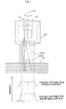
- the energy distribution of the laser light in a cross-section which intersects the turning center axis depends upon the diameter of the turning locus S. It exhibits the triangular shape having a gradual summit when the diameter is small. It exhibits the shape of somma when the diameter is large.
- the energy distribution of the laser light of the present invention which irradiates the skin surface exhibits a uniform energy distribution having a low peak height and which is relatively higher over a wider area in contrast to the Gaussian distribution in the prior art in which the position of the laser transmitting member is always fixed, that is the energy distribution in which the peak in the center is higher and the gradient is steep and the slope is narrow.
- the entire area of the object of the tissue M can be irradiated with the laser light so that the energy distribution over the tissue M is uniform.
- the tissue can be positively and uniformly irradiated with the laser light over the wider area thereof without giving any local damage to the tissue.
- a reflector cylinder which reflects the laser light on the inner surface in front of the tip end of the laser light transmitting member in an coaxial manner with respect to the turning center axis so that the reflected laser light is incident upon the tissue.
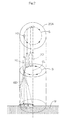
- Part of the laser light emitted from the front end of the laser light transmitting member is reflected on the inner surface of the reflected cylinder and is incident upon the tissue. Accordingly, since the laser light which is reflected on the inner surface 20A of the reflector cylinder 20 is additively incident upon the tissue, the irradiation energy of the laser light on the tissue exhibits substantially inverted U shape, so that the wider area of the object tissue can be uniformly irradiated with laser light.
- the reflector cylinder may be transparent or semi-transparent. In this configuration, the inner tissue is visible through the reflector cylinder. In case of evaporation of the skin blotch, irradiation of the laser light is enabled while confirming the position of the blotch during treatment.
- the reflector cylinder When the reflector cylinder is applied to the surface of the tissue, it may serve as a member for keeping the distance between the tissue and the front end of the laser light transmitting member.
- the reflector cylinder may be removably mounted on the holding means.
- a plurality of kinds of reflector cylinders having different lengths are provided.
- cooling medium pumping means for pumping a cooling medium into the reflector cylinder to cool the surface of the tissue. Since the skin is irradiated with laser light without applying anesthesia, the skin which is irradiated with the laser light may be heated so that the patient can not endure it. In this case, the surface of the tissue can be cooled by pumping a cooling medium into the reflector cylinder for mitigating the hot feeling of the patient. If the reflector cylinder is formed on its wall with the opening, the cooling medium would formed on its wall with the opening, the cooling medium would be pumped out from an opening so that the heat which is recovered by the cooling medium can be discharged to the outside.
- the cooling medium can be pumped into the inside of the reflector cylinder via the holding means.
- the holding means may comprise a casing and a guide whichi s disposed within said casing in such a manner that it is rotatable around a turning center axis.
- the laser light transmitting member may be an optical fiber.
- the turning means may be a motor whichi s disposed within said holding means. At least front end portion of said optical fiber is held by being inserted into said guide with play at a position offset from said turning center axis in such a manner that it is in substantially parallel with said turning center axis.
- the guide is disposed to be rotated by a torque from said motor. Since the optical fiber is inserted into the guide with play in parallel with the turning center axis at this time, the optical fiber only traces a turning locus without following the rotation of the guide, that is, without being not twisted.
- the torque of said motor may be transmitted to said guide via a gear mechanism for rotating the guide. Adopting a gear mechanism for transmitting the torque makes the apparatus more compact.
- the laser light supplying means is capable of supplying pulsated laser light to said laser light transmitting member.
- Use of pulsated laser light allows the laser light having a high energy to be given to the tissue within a shorter interval. Heat feeling for the patient is less in comparison with use of continuous wave.
- the apparatus In case in which pulsated laser light is used, it is preferable to design the apparatus so that the ratio of the number of teeth of the gear on the side of the guide of the gear mechanism to that of the gear on the side of the motor is not a whole number, but a fraction. If the pulsated laser light is irradiated at a given interval and the turning speed is constant, there is the possibility that the tissue is irradiated with the laser light at the same position on the turning locus. If the ratio of the number of the teeth of the gear on the side of the guide of the gear mechanism to that of the gear on the side of the motor is not a whole number, but a fraction, the tissue is irradiated with the laser light at different positions on the turning locus. Accordingly, the tissue can be uniformly irradiated with the laser light over an entire area within a predetermined period of time.
- a plurality of laser light transmitting members may be provided. They may be provided at different positions on the turning locus, or alternatively may be held on the holding means at different radius positions from the turning center axis. If the plurality of laser transmitting members are provided, the irradiation energy which is a multiple times as much as the number of the laser light transmitting members can be supplied per unit time. The embodiment in which the laser light transmitting members are provided at different radial positions far from the turning center axis in effective to provide a wider irradiation area.
- YAG pulsated laser light is excellent in treatment efficiency.
- the apparatus for irradiating a living body with laser light of the present invention is applicable to the removal of the hair and the tartar of the teeth as well as the removal of the blotch on the skin surface.
- it is applicable to the laser light treatment using an endoscope. It is to be noted that the object to be treated with the present apparatus is not restricted.
- An optical fiber 10 is used as a laser light transmitting member of the present invention.
- Laser light from laser light generating source is incident upon the rear end of the optical fiber 10 and is transmitted therethrough and is emitted from the front end thereof and is incident upon the living tissue M, such as the skin.
- a clad is removed from the illustrated optical fiber 10 at the front end thereof so that its core is exposed.
- the optical fiber 10 is held by holding means such as handpiece.
- turning means including a motor for moving the tip end portion of the optical fiber 10 along a circular turning locus S substantially around a turning center axis CL.
- the tip end of the optical fiber 10 is turned along the circular turning locus S around the turning center axis CL at a high r.p.m., such as a few tens to a few ten thousands of r.p.m. Accordingly, the optical axis of the laser light also traces a circular locus in the cross section.
- the laser light is emitted from the tip end of the optical fiber 10 in the course of high speed turning of the optical fiber along the turning locus S to exhibit Caussian distribution.
- the Gaussian distribution of the energy of the incident laser light GD in a longitudinal section is shown in Fig. 2.
- the energy distribution of the laser light which is incident upon the tissue M is a resultant Caussian distribution of the laser light at each position.
- the energy distribution of the laser light which is incident upon the tissue M depends upon the diameter of the turning locus S. It exhibits the triangular shape having a gradual summit when the diameter is small. It exhibits the shape of somma when the diameter is large.
- the energy distribution of the laser light of the present invention which irradiates the skin surface exhibits a uniform energy distribution having a low peak height and which is relatively higher over a wider area.
- the entire area of the object of the tissue M can be irradiated with the laser light so that the energy distribution over the tissue M is uniform.
- the tissue can be positively and uniformly irradiated with the laser light over the wider area thereof without giving any local damage to the tissue.
- a reflector cylinder 20 which reflects the laser light on the inner surface 20A in front of the tip end of the optical fiber 10 in an coaxial manner with respect to the turning center axis CL.
- the reflector cylinder 20 may be made of a plastic material such as acrylic resin and polycarbonate resin, inorganic material such as glass, and metal.
- the cylinder 20 may be preferably transparent or semitransparent. From the view point of this, acrylic resin, polycarbonate resin, class, quartz, sapphire are preferable.
- Disposition of the reflector cylinder 20 causes part of the laser light emitted from the tip end of the optical fiber 10 to be totally reflected on the inner surface 20A of the reflector cylinder 20 and part of it to be transmitted therethrough and the rest to be reflected and to be incident to the tissue M. Accordingly, since the laser light which is reflected on the inner surface 20A of the reflector cylinder 20 is additively incident upon the tissue M as shown in Figs. 1 and 2, the irradiation energy of the laser light on the tissue M exhibits substantially inverted U shape, so that the wider area of the object tissue M can be uniformly irradiated with laser light.
- the laser light which has been incident upon the surface of the tissue M is scattered within the tissue M.
- a portion below the surface of the tissue M for example, the blotch of the skin is to be evaporated, in order to irradiate a position which is about 1 to 3 mm deeper from the surface of the skin with laser light in a uniform manner, it has been found that the energy distribution of the laser light on the surface of the tissue M preferably be slightly lower around the turning center axis CL and higher at the periphery thereof.
- the reflector cylinder 20 which enables the energy level of the irradiation of the object tissue M to increase at the periphery thereof.
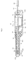
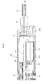
- FIG. 3 to 5 An exemplary configuration of the laser light irradiating apparatus is shown in Figs. 3 to 5, which is suitable for irradiating the tissue surface while it is gripped by a surgeon.
- This laser light irradiating apparatus comprises a casing 30 (handpiece) which serves as holding means and a hollow guide 32 which is disposed within the casing 30 in such a manner that it is rotatable around the turning center axis CL.
- the casing 30 has a removable cover 30B in the rear of a grip body 30A.
- a support cylinder 30C is integral with the grip body 30 at the front end thereof by means of a set screw 31.
- the reflector cylinder 20 is removably mounted on the front end of the support cylinder 30C via a coupler 30D.
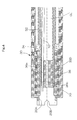
- the hollow tubular guide 32 is held in the support cylinder 30C by front and rear bearings 34 and 34 so that it is rotatable around the turning center axis CL.
- the optical fiber 10 is inserted into the casing 30 through the cover 30B of the casing 30, and further inserted inside the tubular guide 32.
- a holding member 36 is secured integrally within the tip end of the tubular guide 32, and the front end of the optical fiber 10 is held in a groove 36a which is formed on the outer periphery of the holding member 36.
- the front end portion of the optical fiber 10 is held in a position offset from the turning center axis CL with the turning center axis CL due to the fact that the optical fiber is inserted with play inside the groove 36a on the outer periphery of the holding member 36.
- a motor 50 which constitutes turning means is secured within the grip body 30A.
- a prime mover gear 52 is secured to the output shaft of the motor 50.
- the prime move gear 52 is meshed with a follower gear 54 which is integral with the rear portion of the tubular guide 32. Accordingly, the torque of the motor 50 is transmitted to the prime mover gear 52 and the follower gear 54, so that the tubular guide 32 is rotated around the turning center axis CL.
- the ratio of the number of the teeth of the gear (follower gear 54) on the side of the guide of the gear mechanism for transmitting the torque to the number of the teeth of the gear (prime mover gear 52) on the side of the motor is not a whole number, but a fraction. In the embodiment, the ratio is set to 1/32. Since the tissue is irradiated with laser light at different positions on the turning locus S in such an arrangement, the area of the tissue can be uniformly irradiated with laser light within a given period of time.
- the optical fiber 10 Since the front end portion of the optical fiber 10 is inserted with play inside the groove 36a formed on the outer periphery of the holding member 36 at this time, the optical fiber 10 itself does not follow the rotation of the tubular guide 32 and the holding member 36, nor is twisted therefore. The front end portion of the optical fiber 10 only traces a turning locus S.
- the optical fiber 10 is optically coupled with the laser light supplying means.
- the laser light supplying means may include a laser light generator and pulsating means (both not shown).
- the laser light from the laser light supplying means is incident upon the rear end of the optical fiber 10 and is transmitted therethrough and is emitted from the front end thereof so that it is incident upon the tissue M of a living body, for example, the skin.
- the intermediate portion of the optical fiber 10 extends through a guide tube 40, a holder 42 which is secured to the cover 30B, to the inside of the cover 30B.
- a space between the guide tube 40 and the optical fiber 10 serves as an air supplying passage.
- a cooling air is pumped into the casing 30 as a cooling medium by a compressor (not shown).
- the cooling air which has been pumped into the casing 30 is passed through the tubular guide 32 and a hollow 36b of the holding member 36, then enters into the reflecting cylinder 20 and is blown out from total 4 openings 20B which are formed at angularly 90 degrees spaced different positions on the wall of the front end.
- the reflector cylinder 20 is removably mounted on the front end of the support cylinder 30C via the coupler 30D.
- the reflector cylinder 20 which is shown in Figs. 3 to 5 has a short inner surface 20A. It is preferable to provide a plurality of reflector cylinders having different length inner surfaces 20A. A reflector cylinder 20 having a longer inner surface 20A is shown in Fig. 1.
- cooling medium pumping means for pumping a cooling medium into the reflector cylinder 20 to cool the surface of the tissue. Since the skin is irradiated with laser light without applying anesthesia, the skin which is irradiated with the laser light may be heated so that the patient can not endure it. In this case, the surface of the tissue M can be cooled by pumping a cooling medium into the reflector cylinder for mitigating the hot feeling of the patient.
- the cooling medium may include air, water, alcohol, carboxymethylcellulose. A liquid in which a high molecular gel is mixed with water or alcohol for adjusting its viscosity is effective. The volatile liquids have high cooling effect due to their vaporization heat.
- the cooling medium may be continuously or intermittently pumped into the reflecting cylinder. If the reflector cylinder 20 is formed on its wall with the opening 20B, the cooling medium would be pumped out from an opening 20B, so that the heat which is recovered by the cooling medium can be discharged to the outside.
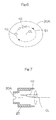
- optical fiber 20 traces the circular turning locus S in the foregoing embodiment, it may trace other shape such as elliptical turning locus S as shown in Fig. 6. Means for this purpose such as cam is readily conceivable for those skilled in the art.
- the optical axis of the optical fiber 10 may not be parallel to the turning center axis CL, but slightly inclined thereto.
- a plurality of the optical fiber 10 may be disposed. For example, they may be on the turning locus at different positions and may be disposed at different radius positions as shown in Fig. 8. If the irradiation area of the object is constant, the irradiation energy which is a multiple of the irradiation area per unit time can be provided and the irradiation area of the object can be widened.
- the turning means may be disposed externally of the casing.
- the reflector cylinder may be omitted if necessary.
- the optical fiber may be replaced with glass or quartz rod as the laser light transmitting member.
- the laser light having a wave length, from which the wave length not higher than 650 nm is eliminated may be preferably used, for example, the treatment of the blotch on the skin.
- laser light having a length of 650 nm or more from krypton lamp, alexandrite (wave length 755 nm), in particular Nd:YAG laser (wave length 1064 nm) is preferable.
- Continuous or pulsated laser light may be preferably used.
- the pulsated laser light is emitted at, for example, 5 to 10 pps.
- the output of the laser light is preferably 0.1 to 35 per one pulse.
Landscapes
- Health & Medical Sciences (AREA)
- Physics & Mathematics (AREA)
- Life Sciences & Earth Sciences (AREA)
- Surgery (AREA)
- Optics & Photonics (AREA)
- Animal Behavior & Ethology (AREA)
- Veterinary Medicine (AREA)
- Public Health (AREA)
- General Health & Medical Sciences (AREA)
- Otolaryngology (AREA)
- Heart & Thoracic Surgery (AREA)
- Medical Informatics (AREA)
- Molecular Biology (AREA)
- Biomedical Technology (AREA)
- Engineering & Computer Science (AREA)
- Nuclear Medicine, Radiotherapy & Molecular Imaging (AREA)
- Electromagnetism (AREA)
- Oral & Maxillofacial Surgery (AREA)
- Dentistry (AREA)
- Epidemiology (AREA)
- Laser Surgery Devices (AREA)
- Radiation-Therapy Devices (AREA)
Applications Claiming Priority (2)
| Application Number | Priority Date | Filing Date | Title |
|---|---|---|---|
| JP2000000604A JP2001190565A (ja) | 2000-01-06 | 2000-01-06 | 生体へのレーザ光照射装置 |
| JP2000000604 | 2000-01-06 |
Publications (2)
| Publication Number | Publication Date |
|---|---|
| EP1118311A2 true EP1118311A2 (de) | 2001-07-25 |
| EP1118311A3 EP1118311A3 (de) | 2002-07-17 |
Family
ID=18529927
Family Applications (1)
| Application Number | Title | Priority Date | Filing Date |
|---|---|---|---|
| EP01100019A Withdrawn EP1118311A3 (de) | 2000-01-06 | 2001-01-04 | Apparat zur Laserbestrahlung des Körpers |
Country Status (2)
| Country | Link |
|---|---|
| EP (1) | EP1118311A3 (de) |
| JP (1) | JP2001190565A (de) |
Cited By (5)
| Publication number | Priority date | Publication date | Assignee | Title |
|---|---|---|---|---|
| WO2003047693A3 (en) * | 2001-11-14 | 2003-07-31 | Healing Machines Inc | System and method for light activation of healing mechanisms |
| WO2008057154A3 (en) * | 2006-09-06 | 2008-08-21 | Shaser Inc | Scanning laser system for the treatment of tissue |
| US7979121B2 (en) | 2002-06-14 | 2011-07-12 | Lazure Scientific, Inc. | Method and apparatus for physiological treatment with electromagnetic energy |
| CN104780860A (zh) * | 2012-11-13 | 2015-07-15 | 奥林巴斯株式会社 | 激光烧灼装置 |
| US9492231B2 (en) | 2009-07-14 | 2016-11-15 | Brian Cisell | Laser surgery device and method |
Families Citing this family (7)
| Publication number | Priority date | Publication date | Assignee | Title |
|---|---|---|---|---|
| US20050053895A1 (en) | 2003-09-09 | 2005-03-10 | The Procter & Gamble Company Attention: Chief Patent Counsel | Illuminated electric toothbrushes emitting high luminous intensity toothbrush |
| US20050050659A1 (en) | 2003-09-09 | 2005-03-10 | The Procter & Gamble Company | Electric toothbrush comprising an electrically powered element |
| DE102004032861A1 (de) * | 2004-07-07 | 2006-02-02 | Khs Maschinen- Und Anlagenbau Ag | Verfahren sowie Vorrichtung zum Sterilisieren von Behältern mit UV-Strahlung |
| US7837675B2 (en) | 2004-07-22 | 2010-11-23 | Shaser, Inc. | Method and device for skin treatment with replaceable photosensitive window |
| JP6050179B2 (ja) * | 2013-05-13 | 2016-12-21 | 飛鳥メディカル株式会社 | レーザーサーミア用のロータリーハンドピース |
| US12279812B2 (en) | 2019-08-05 | 2025-04-22 | Gyrus Acmi, Inc. | Laser fiber varying lateral position and intensity |
| WO2021026136A1 (en) * | 2019-08-05 | 2021-02-11 | Gyrus Acmi, Inc. D/B/A Olympus Surgical Technologies America | Laser fiber varying lateral position and intensity |
Citations (2)
| Publication number | Priority date | Publication date | Assignee | Title |
|---|---|---|---|---|
| JPS5883973A (ja) | 1981-11-13 | 1983-05-19 | 株式会社東芝 | レ−ザ装置 |
| JPH08111A (ja) | 1994-06-15 | 1996-01-09 | Takashi Harada | 土なし栽培装置 |
Family Cites Families (8)
| Publication number | Priority date | Publication date | Assignee | Title |
|---|---|---|---|---|
| GB8816648D0 (en) * | 1988-07-13 | 1988-08-17 | Rowland A C | Light delivery system |
| US5474549A (en) * | 1991-07-09 | 1995-12-12 | Laserscope | Method and system for scanning a laser beam for controlled distribution of laser dosage |
| US5519534A (en) * | 1994-05-25 | 1996-05-21 | The Government Of The United States Of America As Represented By The Secretary Of The Department Of Health And Human Services | Irradiance attachment for an optical fiber to provide a uniform level of illumination across a plane |
| US5835648A (en) * | 1996-03-07 | 1998-11-10 | Miravant Systems, Inc. | Surface illuminator for photodynamic therapy |
| US5820626A (en) * | 1996-07-30 | 1998-10-13 | Laser Aesthetics, Inc. | Cooling laser handpiece with refillable coolant reservoir |
| US5968033A (en) * | 1997-11-03 | 1999-10-19 | Fuller Research Corporation | Optical delivery system and method for subsurface tissue irradiation |
| WO1999046005A1 (en) * | 1998-03-12 | 1999-09-16 | Palomar Medical Technologies, Inc. | System for electromagnetic radiation of the skin |
| US6264649B1 (en) * | 1998-04-09 | 2001-07-24 | Ian Andrew Whitcroft | Laser treatment cooling head |
-
2000
- 2000-01-06 JP JP2000000604A patent/JP2001190565A/ja active Pending
-
2001
- 2001-01-04 EP EP01100019A patent/EP1118311A3/de not_active Withdrawn
Patent Citations (2)
| Publication number | Priority date | Publication date | Assignee | Title |
|---|---|---|---|---|
| JPS5883973A (ja) | 1981-11-13 | 1983-05-19 | 株式会社東芝 | レ−ザ装置 |
| JPH08111A (ja) | 1994-06-15 | 1996-01-09 | Takashi Harada | 土なし栽培装置 |
Cited By (9)
| Publication number | Priority date | Publication date | Assignee | Title |
|---|---|---|---|---|
| WO2003047693A3 (en) * | 2001-11-14 | 2003-07-31 | Healing Machines Inc | System and method for light activation of healing mechanisms |
| US6811565B2 (en) | 2001-11-14 | 2004-11-02 | Healing Machines, Inc. | System and method for light activation of healing mechanisms |
| US7979121B2 (en) | 2002-06-14 | 2011-07-12 | Lazure Scientific, Inc. | Method and apparatus for physiological treatment with electromagnetic energy |
| WO2008057154A3 (en) * | 2006-09-06 | 2008-08-21 | Shaser Inc | Scanning laser system for the treatment of tissue |
| US8246612B2 (en) | 2006-09-06 | 2012-08-21 | Shaser, Inc. | Scanning laser system for the treatment of tissue |
| US9492231B2 (en) | 2009-07-14 | 2016-11-15 | Brian Cisell | Laser surgery device and method |
| CN104780860A (zh) * | 2012-11-13 | 2015-07-15 | 奥林巴斯株式会社 | 激光烧灼装置 |
| EP2921126A4 (de) * | 2012-11-13 | 2016-07-06 | Olympus Corp | Laserablationsvorrichtung |
| CN104780860B (zh) * | 2012-11-13 | 2017-10-17 | 奥林巴斯株式会社 | 激光烧灼装置 |
Also Published As
| Publication number | Publication date |
|---|---|
| EP1118311A3 (de) | 2002-07-17 |
| JP2001190565A (ja) | 2001-07-17 |
Similar Documents
| Publication | Publication Date | Title |
|---|---|---|
| US5733277A (en) | Optical fibre and laser for removal of arterial or vascular obstructions | |
| EP1118311A2 (de) | Apparat zur Laserbestrahlung des Körpers | |
| JP3261525B2 (ja) | レーザ器具 | |
| EP0673627B1 (de) | Katheter mit Lichtleitfaser | |
| CN1178715C (zh) | 激光外科装置及其使用方法 | |
| EP0637942B1 (de) | Medizinische vorrichtung | |
| US4760840A (en) | Endoscopic laser instrument | |
| US4862886A (en) | Laser angioplasty | |
| CA1275450C (en) | Infrared laser catheter system | |
| Verdaasdonk et al. | Laser light delivery systems for medical applications | |
| JP3638191B2 (ja) | 医療用レーザハンドピース | |
| JP2591032Y2 (ja) | 光ファイバレーザ導光拡散プローブ | |
| US8657811B2 (en) | Intravascular diagnostic or therapeutic apparatus using high-intensity pulsed light | |
| EP0562988A1 (de) | Handstück zum Abgeben einer Laserbestrahlung | |
| US20100185188A1 (en) | Electromagnetically induced treatment devices and methods | |
| US9681917B2 (en) | Fiber laser system for medical applications | |
| JP2008508034A (ja) | 触覚的フィードバックの先端部フェルールを有するコントラ・アングル回転型のハンドピース | |
| EP0625271A1 (de) | Verfahren und vorrichtung zum übertragen von laserstrahlung | |
| WO2002007629A1 (en) | Active endoscopic photodynamic therapy devices; systems and method | |
| JP2003265498A (ja) | 生体組織へのレーザ光の照射装置 | |
| JP2001161709A (ja) | レーザ治療装置及びレーザハンドピース | |
| US12239416B2 (en) | Light therapy diagnostic device and method for operating the same | |
| JPH08103508A (ja) | 癌治療器 | |
| JPH0843693A (ja) | 光ファイバレーザデバイス | |
| JP2002017746A (ja) | レーザ照射装置 |
Legal Events
| Date | Code | Title | Description |
|---|---|---|---|
| PUAI | Public reference made under article 153(3) epc to a published international application that has entered the european phase |
Free format text: ORIGINAL CODE: 0009012 |
|
| AK | Designated contracting states |
Kind code of ref document: A2 Designated state(s): AT BE CH CY DE DK ES FI FR GB GR IE IT LI LU MC NL PT SE TR |
|
| AX | Request for extension of the european patent |
Free format text: AL;LT;LV;MK;RO;SI |
|
| PUAL | Search report despatched |
Free format text: ORIGINAL CODE: 0009013 |
|
| AK | Designated contracting states |
Kind code of ref document: A3 Designated state(s): AT BE CH CY DE DK ES FI FR GB GR IE IT LI LU MC NL PT SE TR |
|
| AX | Request for extension of the european patent |
Free format text: AL;LT;LV;MK;RO;SI |
|
| RIC1 | Information provided on ipc code assigned before grant |
Free format text: 7A 61B 18/20 A, 7A 61N 5/06 B |
|
| AKX | Designation fees paid | ||
| REG | Reference to a national code |
Ref country code: DE Ref legal event code: 8566 |
|
| STAA | Information on the status of an ep patent application or granted ep patent |
Free format text: STATUS: THE APPLICATION IS DEEMED TO BE WITHDRAWN |
|
| 18D | Application deemed to be withdrawn |
Effective date: 20030118 |