EP1118466A2 - Flüssigkeitsausstosskopf - Google Patents
Flüssigkeitsausstosskopf Download PDFInfo
- Publication number
- EP1118466A2 EP1118466A2 EP01101132A EP01101132A EP1118466A2 EP 1118466 A2 EP1118466 A2 EP 1118466A2 EP 01101132 A EP01101132 A EP 01101132A EP 01101132 A EP01101132 A EP 01101132A EP 1118466 A2 EP1118466 A2 EP 1118466A2
- Authority
- EP
- European Patent Office
- Prior art keywords
- flowing
- pressure
- electrocasting
- path
- space
- Prior art date
- Legal status (The legal status is an assumption and is not a legal conclusion. Google has not performed a legal analysis and makes no representation as to the accuracy of the status listed.)
- Granted
Links
- 239000007788 liquid Substances 0.000 title claims abstract description 96
- 238000007789 sealing Methods 0.000 claims abstract description 42
- 239000000758 substrate Substances 0.000 claims description 199
- 229920005989 resin Polymers 0.000 claims description 68
- 239000011347 resin Substances 0.000 claims description 68
- 238000000034 method Methods 0.000 claims description 48
- PXHVJJICTQNCMI-UHFFFAOYSA-N Nickel Chemical compound [Ni] PXHVJJICTQNCMI-UHFFFAOYSA-N 0.000 claims description 42
- 229910052759 nickel Inorganic materials 0.000 claims description 21
- VYZAMTAEIAYCRO-UHFFFAOYSA-N Chromium Chemical compound [Cr] VYZAMTAEIAYCRO-UHFFFAOYSA-N 0.000 claims description 20
- 239000011651 chromium Substances 0.000 claims description 20
- 229910052804 chromium Inorganic materials 0.000 claims description 20
- 239000004020 conductor Substances 0.000 claims description 2
- 238000007641 inkjet printing Methods 0.000 description 76
- 238000004519 manufacturing process Methods 0.000 description 29
- 238000004891 communication Methods 0.000 description 18
- 230000000873 masking effect Effects 0.000 description 15
- 238000000059 patterning Methods 0.000 description 15
- 238000001312 dry etching Methods 0.000 description 13
- 238000003754 machining Methods 0.000 description 13
- 230000000694 effects Effects 0.000 description 12
- 238000003825 pressing Methods 0.000 description 12
- 239000000463 material Substances 0.000 description 9
- XUIMIQQOPSSXEZ-UHFFFAOYSA-N Silicon Chemical compound [Si] XUIMIQQOPSSXEZ-UHFFFAOYSA-N 0.000 description 7
- 229910052751 metal Inorganic materials 0.000 description 7
- 239000002184 metal Substances 0.000 description 7
- 229910052710 silicon Inorganic materials 0.000 description 7
- 239000010703 silicon Substances 0.000 description 7
- 239000013078 crystal Substances 0.000 description 4
- 238000005260 corrosion Methods 0.000 description 3
- 230000007797 corrosion Effects 0.000 description 3
- 238000005530 etching Methods 0.000 description 3
- 239000010935 stainless steel Substances 0.000 description 3
- 229910001220 stainless steel Inorganic materials 0.000 description 3
- NLXLAEXVIDQMFP-UHFFFAOYSA-N Ammonia chloride Chemical compound [NH4+].[Cl-] NLXLAEXVIDQMFP-UHFFFAOYSA-N 0.000 description 2
- RYGMFSIKBFXOCR-UHFFFAOYSA-N Copper Chemical compound [Cu] RYGMFSIKBFXOCR-UHFFFAOYSA-N 0.000 description 2
- XEEYBQQBJWHFJM-UHFFFAOYSA-N Iron Chemical compound [Fe] XEEYBQQBJWHFJM-UHFFFAOYSA-N 0.000 description 2
- QAOWNCQODCNURD-UHFFFAOYSA-N Sulfuric acid Chemical compound OS(O)(=O)=O QAOWNCQODCNURD-UHFFFAOYSA-N 0.000 description 2
- HCHKCACWOHOZIP-UHFFFAOYSA-N Zinc Chemical compound [Zn] HCHKCACWOHOZIP-UHFFFAOYSA-N 0.000 description 2
- 229910052802 copper Inorganic materials 0.000 description 2
- 239000010949 copper Substances 0.000 description 2
- 229920003002 synthetic resin Polymers 0.000 description 2
- 239000000057 synthetic resin Substances 0.000 description 2
- 229910052725 zinc Inorganic materials 0.000 description 2
- 239000011701 zinc Substances 0.000 description 2
- 229910000570 Cupronickel Inorganic materials 0.000 description 1
- BQCADISMDOOEFD-UHFFFAOYSA-N Silver Chemical compound [Ag] BQCADISMDOOEFD-UHFFFAOYSA-N 0.000 description 1
- RTAQQCXQSZGOHL-UHFFFAOYSA-N Titanium Chemical compound [Ti] RTAQQCXQSZGOHL-UHFFFAOYSA-N 0.000 description 1
- 239000002253 acid Substances 0.000 description 1
- 239000000853 adhesive Substances 0.000 description 1
- 230000001070 adhesive effect Effects 0.000 description 1
- 229910052782 aluminium Inorganic materials 0.000 description 1
- XAGFODPZIPBFFR-UHFFFAOYSA-N aluminium Chemical compound [Al] XAGFODPZIPBFFR-UHFFFAOYSA-N 0.000 description 1
- 235000019270 ammonium chloride Nutrition 0.000 description 1
- 239000007767 bonding agent Substances 0.000 description 1
- KGBXLFKZBHKPEV-UHFFFAOYSA-N boric acid Chemical compound OB(O)O KGBXLFKZBHKPEV-UHFFFAOYSA-N 0.000 description 1
- 239000004327 boric acid Substances 0.000 description 1
- 150000001875 compounds Chemical class 0.000 description 1
- YOCUPQPZWBBYIX-UHFFFAOYSA-N copper nickel Chemical compound [Ni].[Cu] YOCUPQPZWBBYIX-UHFFFAOYSA-N 0.000 description 1
- KUNSUQLRTQLHQQ-UHFFFAOYSA-N copper tin Chemical compound [Cu].[Sn] KUNSUQLRTQLHQQ-UHFFFAOYSA-N 0.000 description 1
- TVZPLCNGKSPOJA-UHFFFAOYSA-N copper zinc Chemical compound [Cu].[Zn] TVZPLCNGKSPOJA-UHFFFAOYSA-N 0.000 description 1
- 239000003292 glue Substances 0.000 description 1
- PCHJSUWPFVWCPO-UHFFFAOYSA-N gold Chemical compound [Au] PCHJSUWPFVWCPO-UHFFFAOYSA-N 0.000 description 1
- 229910052737 gold Inorganic materials 0.000 description 1
- 239000010931 gold Substances 0.000 description 1
- 238000010438 heat treatment Methods 0.000 description 1
- 238000007654 immersion Methods 0.000 description 1
- 229910052742 iron Inorganic materials 0.000 description 1
- UGKDIUIOSMUOAW-UHFFFAOYSA-N iron nickel Chemical compound [Fe].[Ni] UGKDIUIOSMUOAW-UHFFFAOYSA-N 0.000 description 1
- KBJMLQFLOWQJNF-UHFFFAOYSA-N nickel(ii) nitrate Chemical compound [Ni+2].[O-][N+]([O-])=O.[O-][N+]([O-])=O KBJMLQFLOWQJNF-UHFFFAOYSA-N 0.000 description 1
- 229910052709 silver Inorganic materials 0.000 description 1
- 239000004332 silver Substances 0.000 description 1
- 239000010936 titanium Substances 0.000 description 1
- 229910052719 titanium Inorganic materials 0.000 description 1
Images


Classifications
-
- B—PERFORMING OPERATIONS; TRANSPORTING
- B41—PRINTING; LINING MACHINES; TYPEWRITERS; STAMPS
- B41J—TYPEWRITERS; SELECTIVE PRINTING MECHANISMS, i.e. MECHANISMS PRINTING OTHERWISE THAN FROM A FORME; CORRECTION OF TYPOGRAPHICAL ERRORS
- B41J2/00—Typewriters or selective printing mechanisms characterised by the printing or marking process for which they are designed
- B41J2/005—Typewriters or selective printing mechanisms characterised by the printing or marking process for which they are designed characterised by bringing liquid or particles selectively into contact with a printing material
- B41J2/01—Ink jet
- B41J2/135—Nozzles
- B41J2/16—Production of nozzles
- B41J2/1621—Manufacturing processes
- B41J2/1625—Manufacturing processes electroforming
-
- B—PERFORMING OPERATIONS; TRANSPORTING
- B41—PRINTING; LINING MACHINES; TYPEWRITERS; STAMPS
- B41J—TYPEWRITERS; SELECTIVE PRINTING MECHANISMS, i.e. MECHANISMS PRINTING OTHERWISE THAN FROM A FORME; CORRECTION OF TYPOGRAPHICAL ERRORS
- B41J2/00—Typewriters or selective printing mechanisms characterised by the printing or marking process for which they are designed
- B41J2/005—Typewriters or selective printing mechanisms characterised by the printing or marking process for which they are designed characterised by bringing liquid or particles selectively into contact with a printing material
- B41J2/01—Ink jet
- B41J2/135—Nozzles
- B41J2/14—Structure thereof only for on-demand ink jet heads
- B41J2/14201—Structure of print heads with piezoelectric elements
- B41J2/14274—Structure of print heads with piezoelectric elements of stacked structure type, deformed by compression/extension and disposed on a diaphragm
-
- B—PERFORMING OPERATIONS; TRANSPORTING
- B41—PRINTING; LINING MACHINES; TYPEWRITERS; STAMPS
- B41J—TYPEWRITERS; SELECTIVE PRINTING MECHANISMS, i.e. MECHANISMS PRINTING OTHERWISE THAN FROM A FORME; CORRECTION OF TYPOGRAPHICAL ERRORS
- B41J2/00—Typewriters or selective printing mechanisms characterised by the printing or marking process for which they are designed
- B41J2/005—Typewriters or selective printing mechanisms characterised by the printing or marking process for which they are designed characterised by bringing liquid or particles selectively into contact with a printing material
- B41J2/01—Ink jet
- B41J2/135—Nozzles
- B41J2/16—Production of nozzles
- B41J2/1607—Production of print heads with piezoelectric elements
- B41J2/1612—Production of print heads with piezoelectric elements of stacked structure type, deformed by compression/extension and disposed on a diaphragm
-
- B—PERFORMING OPERATIONS; TRANSPORTING
- B41—PRINTING; LINING MACHINES; TYPEWRITERS; STAMPS
- B41J—TYPEWRITERS; SELECTIVE PRINTING MECHANISMS, i.e. MECHANISMS PRINTING OTHERWISE THAN FROM A FORME; CORRECTION OF TYPOGRAPHICAL ERRORS
- B41J2/00—Typewriters or selective printing mechanisms characterised by the printing or marking process for which they are designed
- B41J2/005—Typewriters or selective printing mechanisms characterised by the printing or marking process for which they are designed characterised by bringing liquid or particles selectively into contact with a printing material
- B41J2/01—Ink jet
- B41J2/135—Nozzles
- B41J2/16—Production of nozzles
- B41J2/1621—Manufacturing processes
- B41J2/1626—Manufacturing processes etching
- B41J2/1628—Manufacturing processes etching dry etching
-
- B—PERFORMING OPERATIONS; TRANSPORTING
- B41—PRINTING; LINING MACHINES; TYPEWRITERS; STAMPS
- B41J—TYPEWRITERS; SELECTIVE PRINTING MECHANISMS, i.e. MECHANISMS PRINTING OTHERWISE THAN FROM A FORME; CORRECTION OF TYPOGRAPHICAL ERRORS
- B41J2/00—Typewriters or selective printing mechanisms characterised by the printing or marking process for which they are designed
- B41J2/005—Typewriters or selective printing mechanisms characterised by the printing or marking process for which they are designed characterised by bringing liquid or particles selectively into contact with a printing material
- B41J2/01—Ink jet
- B41J2/135—Nozzles
- B41J2/16—Production of nozzles
- B41J2/1621—Manufacturing processes
- B41J2/1631—Manufacturing processes photolithography
-
- B—PERFORMING OPERATIONS; TRANSPORTING
- B41—PRINTING; LINING MACHINES; TYPEWRITERS; STAMPS
- B41J—TYPEWRITERS; SELECTIVE PRINTING MECHANISMS, i.e. MECHANISMS PRINTING OTHERWISE THAN FROM A FORME; CORRECTION OF TYPOGRAPHICAL ERRORS
- B41J2/00—Typewriters or selective printing mechanisms characterised by the printing or marking process for which they are designed
- B41J2/005—Typewriters or selective printing mechanisms characterised by the printing or marking process for which they are designed characterised by bringing liquid or particles selectively into contact with a printing material
- B41J2/01—Ink jet
- B41J2/135—Nozzles
- B41J2/16—Production of nozzles
- B41J2/1621—Manufacturing processes
- B41J2/1632—Manufacturing processes machining
- B41J2/1634—Manufacturing processes machining laser machining
-
- B—PERFORMING OPERATIONS; TRANSPORTING
- B41—PRINTING; LINING MACHINES; TYPEWRITERS; STAMPS
- B41J—TYPEWRITERS; SELECTIVE PRINTING MECHANISMS, i.e. MECHANISMS PRINTING OTHERWISE THAN FROM A FORME; CORRECTION OF TYPOGRAPHICAL ERRORS
- B41J2/00—Typewriters or selective printing mechanisms characterised by the printing or marking process for which they are designed
- B41J2/005—Typewriters or selective printing mechanisms characterised by the printing or marking process for which they are designed characterised by bringing liquid or particles selectively into contact with a printing material
- B41J2/01—Ink jet
- B41J2/135—Nozzles
- B41J2/14—Structure thereof only for on-demand ink jet heads
- B41J2002/14387—Front shooter
-
- Y—GENERAL TAGGING OF NEW TECHNOLOGICAL DEVELOPMENTS; GENERAL TAGGING OF CROSS-SECTIONAL TECHNOLOGIES SPANNING OVER SEVERAL SECTIONS OF THE IPC; TECHNICAL SUBJECTS COVERED BY FORMER USPC CROSS-REFERENCE ART COLLECTIONS [XRACs] AND DIGESTS
- Y10—TECHNICAL SUBJECTS COVERED BY FORMER USPC
- Y10T—TECHNICAL SUBJECTS COVERED BY FORMER US CLASSIFICATION
- Y10T29/00—Metal working
- Y10T29/42—Piezoelectric device making
-
- Y—GENERAL TAGGING OF NEW TECHNOLOGICAL DEVELOPMENTS; GENERAL TAGGING OF CROSS-SECTIONAL TECHNOLOGIES SPANNING OVER SEVERAL SECTIONS OF THE IPC; TECHNICAL SUBJECTS COVERED BY FORMER USPC CROSS-REFERENCE ART COLLECTIONS [XRACs] AND DIGESTS
- Y10—TECHNICAL SUBJECTS COVERED BY FORMER USPC
- Y10T—TECHNICAL SUBJECTS COVERED BY FORMER US CLASSIFICATION
- Y10T29/00—Metal working
- Y10T29/49—Method of mechanical manufacture
- Y10T29/49002—Electrical device making
- Y10T29/49117—Conductor or circuit manufacturing
- Y10T29/49124—On flat or curved insulated base, e.g., printed circuit, etc.
- Y10T29/49155—Manufacturing circuit on or in base
- Y10T29/49156—Manufacturing circuit on or in base with selective destruction of conductive paths
-
- Y—GENERAL TAGGING OF NEW TECHNOLOGICAL DEVELOPMENTS; GENERAL TAGGING OF CROSS-SECTIONAL TECHNOLOGIES SPANNING OVER SEVERAL SECTIONS OF THE IPC; TECHNICAL SUBJECTS COVERED BY FORMER USPC CROSS-REFERENCE ART COLLECTIONS [XRACs] AND DIGESTS
- Y10—TECHNICAL SUBJECTS COVERED BY FORMER USPC
- Y10T—TECHNICAL SUBJECTS COVERED BY FORMER US CLASSIFICATION
- Y10T29/00—Metal working
- Y10T29/49—Method of mechanical manufacture
- Y10T29/49002—Electrical device making
- Y10T29/49117—Conductor or circuit manufacturing
- Y10T29/49124—On flat or curved insulated base, e.g., printed circuit, etc.
- Y10T29/49155—Manufacturing circuit on or in base
- Y10T29/49163—Manufacturing circuit on or in base with sintering of base
-
- Y—GENERAL TAGGING OF NEW TECHNOLOGICAL DEVELOPMENTS; GENERAL TAGGING OF CROSS-SECTIONAL TECHNOLOGIES SPANNING OVER SEVERAL SECTIONS OF THE IPC; TECHNICAL SUBJECTS COVERED BY FORMER USPC CROSS-REFERENCE ART COLLECTIONS [XRACs] AND DIGESTS
- Y10—TECHNICAL SUBJECTS COVERED BY FORMER USPC
- Y10T—TECHNICAL SUBJECTS COVERED BY FORMER US CLASSIFICATION
- Y10T29/00—Metal working
- Y10T29/49—Method of mechanical manufacture
- Y10T29/49002—Electrical device making
- Y10T29/49117—Conductor or circuit manufacturing
- Y10T29/49124—On flat or curved insulated base, e.g., printed circuit, etc.
- Y10T29/49155—Manufacturing circuit on or in base
- Y10T29/49165—Manufacturing circuit on or in base by forming conductive walled aperture in base
-
- Y—GENERAL TAGGING OF NEW TECHNOLOGICAL DEVELOPMENTS; GENERAL TAGGING OF CROSS-SECTIONAL TECHNOLOGIES SPANNING OVER SEVERAL SECTIONS OF THE IPC; TECHNICAL SUBJECTS COVERED BY FORMER USPC CROSS-REFERENCE ART COLLECTIONS [XRACs] AND DIGESTS
- Y10—TECHNICAL SUBJECTS COVERED BY FORMER USPC
- Y10T—TECHNICAL SUBJECTS COVERED BY FORMER US CLASSIFICATION
- Y10T29/00—Metal working
- Y10T29/49—Method of mechanical manufacture
- Y10T29/49401—Fluid pattern dispersing device making, e.g., ink jet
Definitions
- This invention is related to a liquid jetting head, for example an ink-jetting recording head capable of jetting a drop of ink from a nozzle by means of vibration of a piezoelectric vibrating member in order to record images or characters on a recording medium.
- This invention is also related to a method of producing such a liquid jetting head.
- a ink-jetting recording head using longitudinal-vibration type of piezoelectric vibrating members comprises a flowing-path unit 101 provided with a lot of nozzles 108 and a lot of pressure chambers 107.
- the flowing-path unit 101 is stuck onto a head case 102 containing the piezoelectric vibrating members 106.
- the flowing unit 101 consists of a nozzle plate 103 through which the nozzles 108 are formed in two rows, a flowing-path plate 104 through which the pressure chambers 107 respectively communicating with the nozzles 108 are formed and a vibrating plate 105 that seals lower openings of the pressure chambers 107.
- the nozzle plate 103, the flowing-path plate 104 and the vibrating plate 105 are layered one on top of another as shown in Figs.24 and 25.
- ink reservoir spaces 109 are formed for storing ink that is introduced into the respective pressure chambers 107.
- ink-paths 110 are formed in the flowing-path plate 104 for connecting the respective pressure chambers 107 and the ink reservoir spaces 109.
- the head case 102 is made of a synthetic resin.
- the head case 102 has vertical through spaces 112.
- the piezoelectric vibrating members 106 are contained in the spaces 112. Tail ends of the piezoelectric vibrating members 106 are fixed to a fixing plate 111, which is attached to the head case 102. Leading surfaces of the piezoelectric vibrating members 106 are fixed to island portions 105A (see Fig.25) of the vibrating plate 105, respectively.
- the piezoelectric vibrating member 106 When a driving signal generated in a driving circuit 114 is inputted to a piezoelectric vibrating member 106 through a flexible circuit board 113, the piezoelectric vibrating member 106 extends and contracts in a longitudinal direction thereof. When the piezoelectric vibrating member 106 extends and contracts, the corresponding island portion 105A of the vibrating plate 105 vibrates to change a pressure of the ink in the corresponding pressure chamber 107. Thus, the ink in the pressure chamber 107 may be jetted from the corresponding nozzle 108 as a drop of the ink.
- ink supplying ports 115 for supplying the ink to the ink reservoir spaces 109 are formed through the head case 102 and the vibrating plate 105.
- the flowing-path plate 104 of the flowing-path unit 101 conventionally, a plate formed from a silicon mono-crystal substrate by an anisotropic etching process (see Japanese Patent Laid-Open No.9-123448), a plate having a layer made of a photosensitive resin, and an electrocasting plate peeled off from a jig substrate (see Japanese Patent Laid-Open No.6-305142 and Japanese Patent Laid-Open No.9-300635) may be used.
- a flowing-path plate 104 In a case of forming a flowing-path plate 104 from a silicon mono-crystal substrate by an anisotropic etching process, pressure chambers 107 and ink-paths 110 are formed by the etching process.
- the etched silicon mono-crystal substrate (flowing-path plate 104) is layered with a metal nozzle plate 103 and a vibrating plate 105 via an adhesive material or the like.
- a linear expansion coefficient of silicon mono-crystal is different from a linear expansion coefficient of metal.
- a so-called "warp" may occur in the flowing-path unit 101 consisting of the layered plates 103-105. This is not serious in the small-sized recording head, but this may result in difficulty in enlarging the size of the recording head.
- a Young's modulus of the photosensitive resin (flowing-path plate 104) is lower than that of metal or silicon. That is, the photosensitive resin has only a lower rigidity.
- the pressure chambers 107 are arranged more densely, boundary walls therebetween may deform by means of a pressure in an adjacent pressure chamber 107, that is, "cross-talk" may occur. Therefore, in the case, it is difficult to densely arrange the nozzles.
- a "warp" of the elctrrocasting layer may tend to occur during the peeling off from the jig substrate. That is, dimension accuracy of the flowing-path plate 104 may tend to be lower.
- the case needs a step of forming the electrocasting layer on the jig substrate and a step of peeling off the electrocasting layer from the jig substrate, which may result in longer time and greater cost.
- the object of this invention is to solve the above problems, that is, to provide a liquid jetting head such as an ink-jet recording head wherein a "warp" of a flowing-path plate is prevented so that the liquid jetting head can be advantageously made more accurate, enlarged and made denser.
- a liquid jetting head includes: a flowing-path plate through which a flowing-path space is formed as a flowing-path for a liquid; a nozzle plate provided on one side surface of the flowing-path plate, said nozzle plate having a nozzle that is communicated with the flowing-path space; and a sealing plate provided on the other side surface of the flowing-path plate for sealing the flowing-path space; wherein a portion of the other side of the flowing-path space forms a pressure-chamber space; a portion of the other side of the flowing-path plate including at least a portion of the pressure-chamber space is formed by electrocasting; and a pressure-generating unit is provided at a portion of the other side of the sealing plate corresponding to the pressure-chamber space for changing a pressure of the liquid in the pressure-chamber space.
- the portion of the other side of the flowing-path plate is formed by electrocasting, a "warp" of the flowing-path plate may be prevented.
- the flowing-path plate may be formed more accurately.
- the portion formed by electrocasting includes at least the portion of the pressure-chamber space, preferably the whole pressure-chamber space, boundary walls defining the pressure-chamber space may have a relatively higher rigidity.
- the pressure-chamber spaces may be arranged more densely. Therefore, the liquid jetting head is advantageous in being made denser, made more accurate, and enlarged.
- the pressure-chamber space is formed as the portion of the flowing-path space, the pressure-chamber space may be easily positioned relative to the nozzle. Thus, it may be prevented that an air bubble is generated and stays in the flowing-path space. In addition, a step of peeling off the electrocasting portion is unnecessary, which is advantageous in cost.
- the flowing-path plate has a substrate layer and an electrocasting layer formed on the other side surface of the substrate layer by electrocasting.
- the liquid jetting head may be easily produced.
- the pressure-chamber space is formed in the electrocasting layer as a through hole having substantially the same shape in a depth direction thereof, the one side surface of the pressure-chamber space is defined by the substrate layer, the other side surface of the pressure-chamber space is defined by the sealing plate, and lateral side surfaces of the pressure-chamber space are defined by the electrtocasting layer.
- a communicating hole may be formed in the substrate layer for connecting the pressure-chamber space and the nozzle.
- the substrate layer and the nozzle plate may be formed integratedly.
- the flowing-path plate may have a substrate layer, an electrocasting layer formed on the other side surface of the substrate layer by electrocasting and a second electrocasting layer formed on the one side surface of the substrate layer by electrocasting.
- the liquid jetting head may be easily produced as well.
- the pressure-chamber space is formed in the electrocasting layer as a through hole having substantially a same shape in a depth direction thereof, the one side surface of the pressure-chamber space is defined by the substrate layer, the other side surface of the pressure-chamber space is defined by the sealing plate, lateral side surfaces of the pressure-chamber space are defined by the electrtocasting layer, a second pressure-chamber space is formed in the second electrocasting layer as a through hole having substantially a same shape in a depth direction thereof, the second pressure-chamber space is communicated with the nozzle, the one side surface of the second pressure-chamber space is defined by the nozzle plate, the other side surface of the second pressure-chamber space is defined by the substrate layer, and lateral side surfaces of the second pressure-chamber space are defined by the second electrtocasting layer.
- a communicating hole may be formed in the substrate layer for connecting the pressure-chamber space and the second pressure-chamber space.
- a thickness of the electrocasting layer and a thickness the second electrocasting layer may be allowed to be thinner.
- the electrocasting step may be shortened.
- a warp of the electrocasting layer and a warp of the second electrocasting layer may be prevented more extremely.
- a thermal expansion coefficient of the electrocasting layer and/or a thermal expansion coefficient of the second electrocasting layer are substantially equal to a thermal expansion coefficient of the substrate layer.
- a warp of the electrocasting layer and/or a warp of the second electrocasting layer may be prevented more extremely.
- the electrocasting layer and/or the second electrocasting layer are made of nickel or chromium, which is superior in adherence to the substrate layer, rigidity, corrosion resistance or the like.
- the substrate layer may be made of an electric conductive material.
- a thickness of the electrocasting layer and/or a thickness of the second electrocasting layer are smaller than a thickness of the substrate layer. In the case, a warp of the electrocasting layer and/or a warp of the second electrocasting layer may be prevented more extremely.
- a liquid reservoir space communicating with the pressure-chamber space may be also formed in the electrocasting layer.
- space may be utilized more efficiently.
- the liquid reservoir space is formed in the electrocasting layer as a through hole having substantially the same shape in a depth direction thereof, the one side surface of the liquid reservoir space is defined by the substrate layer, the other side surface of the liquid reservoir space is defined by the sealing plate, and lateral side surfaces of the liquid reservoir space are defined by the electrtocasting layer.
- a second liquid reservoir space communicating with the second pressure-chamber space may be also formed in the second electrocasting layer.
- the second liquid reservoir space is formed in the second electrocasting layer as a through hole having substantially the same shape in a depth direction thereof, the one side surface of the second liquid reservoir space is defined by the nozzle plate, the other side surface of the second liquid reservoir space is defined by the substrate layer, and lateral side surfaces of the second liquid reservoir space are defined by the second electrtocasting layer.
- the nozzle plate is formed on the one side surface of the flowing-path plate by electrocasting.
- the number of parts and the number of steps for manufacturing the liquid jetting head may be reduced.
- the accuracy of the liquid jetting head may be improved more, and the cost thereof may be reduced more.
- the pressure-generating unit may have a piezoelectric vibrating member that can extend and contract.
- the pressure-generating unit may have a piezoelectric vibrating member that can bend.
- the sealing plate is a vibrating plate that can deform and vibrate.
- the pressure-generating unit may have a heater that can heat the liquid in the pressure-chamber space.
- the sealing plate has a thermal conductivity.
- this invention is a method of producing a liquid jetting head including: a flowing-path plate throughwhich a flowing-path space is formed as a flowing-path for a liquid; a nozzle plate provided on one side surface of the flowing-path plate, said nozzle plate having a nozzle that is communicated with the flowing-path space; and a sealing plate provided on the other side surface of the flowing-path plate for sealing the flowing-path space; wherein a portion of the other side of the flowing-path space forms a pressure-chamber space; a portion of the other side of the flowing-path plate including at least a portion of the pressure-chamber space is formed by electrocasting; a pressure-generating unit is provided at a portion of the other side of the sealing plate corresponding to the pressure-chamber space for changing a pressure of the liquid in the pressure-chamber space; and the flowing-path plate has a substrate layer and an electrocasting layer formed on the other side surface of the substrate layer by electrocasting; comprising;
- the liquid jetting head may be produced more accurately by means of the relatively simpler and easier steps.
- the pattern-forming step may include: a step of applying a photosensitive resin to the other side surface of the substrate layer; and a step of exposing and developing the applied photosensitive resin according to said pattern.
- the pattern may be formed more easily.
- the method may further include a grinding step of grinding the other side surface of the flowing-path plate, after the pattern-removing step.
- a communicating hole may be formed in the substrate layer for connecting the pressure-chamber space and the nozzle, before the pattern-forming step or after the pattern-removing step.
- this invention is a method of producing a liquid jetting head including: a flowing-path plate through which a flowing-path space is formed as a flowing-path for a liquid; a nozzle plate provided on one side surface of the flowing-path plate, said nozzle plate having a nozzle that is communicated with the flowing-path space; and a sealing plate provided on the other side surface of the flowing-path plate for sealing the flowing-path space;
- the pressure-chamber spaces may be formed more accurately on both side surfaces of the substrate layer by means of the relatively simpler and easier steps.
- a time for the steps may be shortened more.
- liquid reservoir space and/or the second liquid reservoir space may be formed by electrocasting, similarly to the flowing-path space. However, it is unnecessary for the liquid reservoir spaces to be formed accurately. Thus, the liquid reservoir spaces may be formed after the pattern-removing step or after the grinding step.
- this invention is a method of producing a liquid jetting head including: a flowing-path plate throughwhich a flowing-path space is formed as a flowing-path for a liquid; a nozzle plate provided on one side surface of the flowing-path plate, said nozzle plate having a nozzle that is communicated with the flowing-path space; and a sealing plate provided on the other side surface of the flowing-path plate for sealing the flowing-path space; wherein a portion of the other side of the flowing-path space forms a pressure-chamber space; a portion of the other side of the flowing-path plate including at least a portion of the pressure-chamber space is formed by electrocasting; a pressure-generating unit is provided at a portion of the other side of the sealing plate corresponding to the pressure-chamber space for changing a pressure of the liquid in the pressure-chamber space; and the nozzle plate is formed on the one side surface of the flowing-path plate by electrocasting; comprising;
- the nozzle plate may be formed by electrocasting by means of the relatively simpler and easier steps.
- the pattern-forming step may include: a step of applying a photosensitive resin to the one side surface of the flowing-path plate; and a step of exposing and developing the applied photosensitive resin according to said pattern.
- the pattern may be formed more easily.
- the method may further comprise a step of forming a communicating hole to the nozzle in the flowing-path plate, before the pattern-forming step.
- the pattern-forming step is a step of forming and sticking a first pattern to seal the communicating hole and a second pattern corresponding to the nozzle of the nozzle plate.
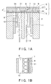
- Figs.1A and 1B show a first embodiment of an ink-jetting recording head (an example of liquid jetting head) according to the invention.
- the ink-jetting recording head includes longitudinal-vibration type of piezoelectric vibrating members.
- the ink-jetting recording head has a flowing-path unit 1 provided with a lot of nozzles 8 and a lot of pressure chambers 7.
- the flowing-path unit 1 is stuck onto a head case 2 containing the piezoelectric vibrating members 6.
- the flowing unit 1 consists of a nozzle plate 3 through which the nozzles 8 are formed in two rows, a flowing-path plate 4 through which the pressure-chamber spaces 7 respectively communicating with the nozzles 8 are formed and a vibrating plate 5 that seals lower openings of the pressure chambers 7.
- the nozzle plate 3, the flowing-path plate 4 and the vibrating plate 5 are layered one on top of another as shown in Fig.1A.
- the nozzle plate 3 is made of stainless steel.
- the flowing-path plate 4 has a substrate 20 (substrate layer) through which communicating holes 21 respectively communicating with the nozzles 8 are formed.
- a flowing-path portion 22 (electrocasting layer) is integratedly formed below the substrate 20 by electrocasting.
- the pressure chambers 7 are formed in the flowing-path portion 22.
- ink reservoir spaces 9 are formed for storing ink that is introduced into the respective pressure chambers 7.
- ink-paths 10 are formed in the flowing-path portion 22 for connecting the respective pressure chambers 7 and the ink reservoir spaces 9.
- the substrate 20 may be made of any material having certain rigidity and certain electric conductivity.
- the substrate 20 may be made of stainless steel, nickel, aluminum, titanium, copper, zinc, or any other metal.
- stainless steel and nickel are preferably used because they are superior in corrosion resistance and easy to be machined.
- the flowing-path portion 22 may be made of any material capable of electrocasting onto the substrate 20.
- the flowing-path portion 22 may be made of silver, gold, copper, chromium, iron, nickel, zinc, or any other pure metal, copper-nickel, copper-tin, copper-zinc, iron-nickel, or any other compound metal.
- chromium and nickel are preferably used because they are superior in adherence to the substrate 20, rigidity, corrosion resistance or the like.
- the material of the substrate 20 is different from the material of the flowing-path portion 22.
- the material of the substrate 20 may be the same as the material of the flowing-path portion 22.
- the head case 2 is made of a synthetic resin.
- the head case 2 has vertical through spaces 12.
- the piezoelectric vibrating members 6 are contained in the spaces 12. Tail ends of the piezoelectric vibrating members 6 are fixed to a fixing plate 11, which is attached to the head case 2. Leading surfaces of the piezoelectric vibrating members 6 are fixed to island portions 5A of the vibrating plate 5, respectively.
- the piezoelectric vibrating member 6 When a driving signal generated in a driving circuit 14 is inputted to a piezoelectric vibrating member 6 through a flexible circuit board 13, the piezoelectric vibrating member 6 extends and contracts in a longitudinal direction thereof. When the piezoelectric vibrating member 6 extends and contracts, the corresponding island portion 5A of the vibrating plate 5 vibrates to change a pressure of the ink in the corresponding pressure chamber 7. Thus, the ink in the pressure chamber 7 may be jetted from the corresponding nozzle 8 as a drop of the ink.
- the flowing-path portion 22 formed by electrocasting and the substrate 20 are integratedly formed.
- a "warp" of the flowing-path portion 22 may be prevented, so that the flowing-path unit 1 can be formed more accurately.
- linear expansion coefficients of the plates that form the flowing-path unit 1 are substantially the same as each other, a "warp" of the flowing-path portion 22 may be prevented so further extremely that enlargement of the flowing-path unit 1 may be enabled.
- boundary walls between adjacent pressure chambers 7 can be made of metal and have such a high rigidity that the pressure chambers 7 can be arranged more densely.
- the substrate 20 and the flowing-path portion 22 are integratedly formed, the nozzle 8 and the communication hole 21 are positioned more accurately with respect to each other. Thus, it may be prevented that an air bubble is generated and stays.
- the substrate 20 and the flowing-path portion 22 are integratedly formed, that is, since a step of peeling off the electrocasting portion is unnecessary, there is an advantage in cost.
- Fig.2 is a view for explaining a first example of a method for producing the ink-jetting recording head shown in Figs.1A and 1B.
- a substrate 20 is prepared.
- communication holes 21 are formed through the substrate 20 by means of a pressing process, a dry-etching process, a laser-machining process or the like.
- a photosensitive resin 24 is applied onto both side surfaces of the substrate 20.
- the photosensitive resin is exposed and developed together with a conventional patterning (masking) tool, so that only a patterned portion 23 of a lower surface of the substrate 20 is exposed.
- the patterned portion 23 corresponds to walls of a flowing-path portion 22. Except for the patterned portion 23, the both side surfaces of the substrate 20 are masked.
- the photosensitive resin 24 may be any type of photosensitive resin capable of resisting immersion into an electrocasting bath.
- the photosensitive resin 24 is preferably a dry-film photo-resist, which can achieve evenness of resin thickness and/or a relatively thicker resin mask.
- the substrate 20 is immersed in the electrocasting bath. Then, a direct-current voltage is applied to the electrocasting bath while using the substrate 20 as a cathode.
- a direct-current voltage is applied to the electrocasting bath while using the substrate 20 as a cathode.
- nickel or chromium is accumulated on the patterned portion 23 by electrocasting.
- the flowing-path portion 22 is formed.
- the electrocasting bath may be any type of electrocasting bath.
- the electrocasting bath may be a nickel-nitrate bath added ammonium chloride and boric acid.
- the electrocasting bath may be a bath consisting of anhydrous chromium acid and sulfuric acid.
- a nozzle plate 3 and a vibrating plate 5 are respectively layered onto the both side surfaces of the flowing-path plate 4, in order to form a flowing-path unit 1 (see Figs.1A and 1B).
- the thickness t2 of the flowing-path portion 22 formed on the substrate 20 is preferably set to be smaller than a thickness tl of the substrate 20.
- the electrocasting may tend not to cause the warp, so that the flowing-path unit 1 may be formed more accurately.
- the flowing-path portion 22 is formed on the substrate 20 by electrocasting.
- the warp of the flowing-path portion 22 may be prevented, so that the flowing-path unit 1 can be formed more accurately.
- the substrate 20 and the flowing-path portion 22 are integratedly formed, that is, since a step of peeling off the electrocasting portion is not included, there is an advantage in cost.
- unevenness of the thickness t2 of the flowing-path portion 22, which may be caused by the electrocasting step may be removed. That is, the thickness may be adjusted more accurately. In particular, if an electrocasting speed is raised in order to increase productivity, unevenness of the thickness t2 may be easily caused during the electrocasting step. In the case, it is very effective to grind the surface of the flowing-path portion 22.
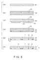
- Fig.3 is a view for explaining a second example of a method for producing the ink-jetting recording head shown in Figs.1A and 1B.
- a substrate 20 is prepared.
- a photosensitive resin 24 is applied onto both side surfaces of the substrate 20.
- the photosensitive resin is exposed and developed together with a conventional patterning (masking) tool, so that only a patterned portion 23 of a lower surface of the substrate 20 is exposed.
- the patterned portion 23 corresponds to walls of a flowing-path portion 22. Except for the patterned portion 23, the both side surfaces of the substrate 20 are masked.
- the substrate 20 is immersed in the electrocasting bath. Then, a direct-current voltage is applied to the electrocasting bath while using the substrate 20 as a cathode. Thus, as shown in Fig.3 (d), nickel or chromium is accumulated on the patterned portion 23 by electrocasting. Thus, the flowing-path portion 22 is formed.
- the photosensitive resin 24 is completely removed. Then, as shown in Fig.3 (e), the photosensitive resin 24 is completely removed. Then, the surface of the flowing-path portion 22 is ground so that a thickness t2 of the flowing-path portion 22 is adjusted to a predetermined uniform thickness. Thus, the flowing-path plate 4 is completed.
- communication holes 21 are formed through the substrate 20 by means of a pressing process, a dry-etching process, a laser-machining process or the like.
- Figs.4A and 4B show a second embodiment of an ink-jetting recording head according to the invention.
- opening portions 9A are formed through portions of the substrate 20 corresponding to the ink reservoir spaces 9, in order to communicate with the ink reservoir spaces 9 and substantially increase capacities thereof.
- Other structure is substantially the same as the first embodiment shown in Fig.1.
- the same numeral references correspond to the same elements as the first embodiment. The explanation of the same elements is not repeated.
- the substrate 20 in addition to the flowing-path portion 22, the substrate 20 has a space for storing the ink.
- the whole space of the flowing-path plate may be utilized more efficiently.
- Volumes of the ink reservoir spaces 9 and the opening portions 9A may be easily designed to be an enough size.
- the second embodiment can have substantially the same advantage as the first embodiment.
- Fig.5 is a view for explaining a third example of a method for producing the ink-jetting recording head according to the invention.
- the third example is for producing the ink-jetting recording head shown in Figs.4A and 4B.
- a substrate 20 is prepared.
- communication holes 21 and opening portions 9A are formed through the substrate 20 by means of a pressing process, a dry-etching process, a laser-machining process or the like.
- a photosensitive resin 24 is applied onto both side surfaces of the substrate 20.
- the photosensitive resin is exposed and developed together with a conventional patterning (masking) tool, so that only a patterned portion 23 of a lower surface of the substrate 20 is exposed.
- the patterned portion 23 corresponds to walls of a flowing-path portion 22. Except for the patterned portion 23, the both side surfaces of the substrate 20 are masked.
- the substrate 20 is immersed in the electrocasting bath. Then, a direct-current voltage is applied to the electrocasting bath while using the substrate 20 as a cathode. Thus, as shown in Fig.5 (e), nickel or chromium is accumulated on the patterned portion 23 by electrocasting. Thus, the flowing-path portion 22 is formed.
- the photosensitive resin 24 is completely removed. Then, as shown in Fig.5 (f), the photosensitive resin 24 is completely removed. Then, the surface of the flowing-path portion 22 is ground so that a thickness t2 of the flowing-path portion 22 is adjusted to a predetermined uniform thickness. Thus, the flowing-path plate 4 is completed.
- Fig.6 is a view for explaining a fourth example of a method for producing the ink-jetting recording head according to the invention.
- the fourth example is also for producing the ink-jetting recording head shown in Figs.4A and 4B.
- a substrate 20 is prepared.
- a photosensitive resin 24 is applied onto both side surfaces of the substrate 20.
- the photosensitive resin is exposed and developed together with a conventional patterning (masking) tool, so that only a patterned portion 23 of a lower surface of the substrate 20 is exposed.
- the patterned portion 23 corresponds to walls of a flowing-path portion 22. Except for the patterned portion 23, the both side surfaces of the substrate 20 are masked.
- the substrate 20 is immersed in the electrocasting bath. Then, a direct-current voltage is applied to the electrocasting bath while using the substrate 20 as a cathode. Thus, as shown in Fig.6 (d), nickel or chromium is accumulated on the patterned portion 23 by electrocasting. Thus, the flowing-path portion 22 is formed.
- the photosensitive resin 24 is completely removed. Then, as shown in Fig.6 (e), the photosensitive resin 24 is completely removed. Then, the surface of the flowing-path portion 22 is ground so that a thickness t2 of the flowing-path portion 22 is adjusted to a predetermined uniform thickness. Thus, the flowing-path plate 4 is completed.
- communication holes 21 and opening portions 9A are formed through the substrate 20 by means of a pressing process, a dry-etching process, a laser-machining process or the like.
- Figs.7A and 7B show a third embodiment of an ink-jetting recording head according to the invention.
- recesses 9B are formed at portions of the substrate 20 corresponding to the ink reservoir spaces 9, in order to communicate with the ink reservoir spaces 9 and substantially increase capacities thereof.
- Other structure is substantially the same as the first embodiment shown in Fig.1.
- the same numeral references correspond to the same elements as the first embodiment. The explanation of the same elements is not repeated.
- the substrate 20 in addition to the flowing-path portion 22, has a space for storing the ink.
- the whole space of the flowing-path plate may be utilized more efficiently.
- Volumes of the ink reservoir spaces 9 and the recesses 9B may be easily designed to be an enough size.
- the third embodiment can have substantially the same advantage as the first embodiment.
- Fig.8 is a view for explaining a fifth example of a method for producing the ink-jetting recording head according to the invention.
- the fifth example is for producing the ink-jetting recording head shown in Figs.7A and 7B.
- a substrate 20 is prepared.
- Fig.8 (b) communication holes 21 and recesses 9B are formed in the substrate 20 by means of a pressing process, a dry-etching process, a laser-machining process or the like.
- a photosensitive resin 24 is applied onto both side surfaces of the substrate 20.
- the photosensitive resin is exposed and developed together with a conventional patterning (masking) tool, so that only a patterned portion 23 of a lower surface of the substrate 20 is exposed.
- the patterned portion 23 corresponds to walls of a flowing-path portion 22. Except for the patterned portion 23, the both side surfaces of the substrate 20 are masked.
- the substrate 20 is immersed in the electrocasting bath. Then, a direct-current voltage is applied to the electrocasting bath while using the substrate 20 as a cathode. Thus, as shown in Fig.8 (e), nickel or chromium is accumulated on the patterned portion 23 by electrocasting. Thus, the flowing-path portion 22 is formed.
- the photosensitive resin 24 is completely removed. Then, as shown in Fig.8 (f), the photosensitive resin 24 is completely removed. Then, the surface of the flowing-path portion 22 is ground so that a thickness t2 of the flowing-path portion 22 is adjusted to a predetermined uniform thickness. Thus, the flowing-path plate 4 is completed.
- Fig.9 is a view for explaining a sixth example of a method for producing the ink-jetting recording head according to the invention.
- the sixth example is also for producing the ink-jetting recording head shown in Figs.7A and 7B.
- a substrate 20 is prepared at first, as shown in Fig.9 (a).
- a photosensitive resin 24 is applied onto both side surfaces of the substrate 20.
- the photosensitive resin is exposed and developed together with a conventional patterning (masking) tool, so that only a patterned portion 23 of a lower surface of the substrate 20 is exposed.
- the patterned portion 23 corresponds to walls of a flowing-path portion 22. Except for the patterned portion 23, the both side surfaces of the substrate 20 are masked.
- the substrate 20 is immersed in the electrocasting bath. Then, a direct-current voltage is applied to the electrocasting bath while using the substrate 20 as a cathode. Thus, as shown in Fig.9 (d), nickel or chromium is accumulated on the patterned portion 23 by electrocasting. Thus, the flowing-path portion 22 is formed.
- the photosensitive resin 24 is completely removed. Then, as shown in Fig.9 (e), the photosensitive resin 24 is completely removed. Then, the surface of the flowing-path portion 22 is ground so that a thickness t2 of the flowing-path portion 22 is adjusted to a predetermined uniform thickness. Thus, the flowing-path plate 4 is completed.
- communication holes 21 and recesses 9B are formed in the substrate 20 by means of a pressing process, a dry-etching process, a laser-machining process or the like.
- Fig.10 shows a fourth embodiment of an ink-jetting recording head according to the invention.
- two flowing-path portions 22 are respectively formed onto the both side surfaces of the substrate 20 by electrocasting, as an electricasing layer and a second electrocasting layer.
- Other structure is substantially the same as the first embodiment shown in Fig. 1.
- the same numeral references correspond to the same elements as the first embodiment. The explanation of the same elements is not repeated.
- the flowing-path portions 22 are formed on the both side surfaces of the substrate 20, a thickness of each of the flowing-path portions 22 may be allowed to be thinner. Thus, the electrocasting step may be shortened. In addition, a warp of each of the flowing-path portions 22 may be prevented more extremely.
- the fourth embodiment can have substantially the same advantage as the first embodiment.
- Fig.11 is a view for explaining a seventh example of a method for producing the ink-jetting recording head according to the invention.
- the seventh example is for producing the ink-jetting recording head shown in Fig.10.
- a substrate 20 is prepared.
- communication holes 21 are formed through the substrate 20 by means of a pressing process, a dry-etching process, a laser-machining process or the like.
- a photosensitive resin 24 is applied onto both side surfaces of the substrate 20.
- the photosensitive resin is exposed and developed together with a conventional patterning (masking) tool, so that only respective patterned portions 23 of the both side surfaces of the substrate 20 are exposed.
- the patterned portions 23 correspond to walls of the respective flowing-path portions 22. Except for the patterned portions 23, the both side surfaces of the substrate 20 are masked.
- the substrate 20 is immersed in the electrocasting bath. Then, a direct-current voltage is applied to the electrocasting bath while using the substrate 20 as a cathode. Thus, as shown in Fig.11 (e), nickel or chromium is accumulated on the patterned portions 23 by electrocasting. Thus, the upper and lower flowing-path portions 22 are formed.
- the photosensitive resin 24 is completely removed. Then, as shown in Fig.11 (f), the photosensitive resin 24 is completely removed. Then, the respective surfaces of the flowing-path portions 22 are ground so that respective thicknesses t3 and t4 of the flowing-path portions 22 are adjusted to predetermined uniform thicknesses. Thus, the flowing-path plate 4 is completed.
- remaining stresses in the respective flowing-path portions 22 may be evenly balanced after the electrocasting step.
- the warp of the flowing-path plate 4 may be prevented more extremely.
- the respective thicknesses t3 and t4 of the two flowing-path portions 22 may be allowed to be thinner than the case of only a single flowing-path portion 22.
- the electrocasting step may be shortened.
- the thicknesses t3 and t4 of the flowing-path portions 22 are respectively thinner than the thickness t1 of the substrate 20.
- the seventh example can achieve substantially the same effect as the first example.
- Fig.12 is a view for explaining an eighth example of a method for producing the ink-jetting recording head according to the invention.
- the eighth example is also for producing the ink-jetting recording head shown in Fig.10.
- a substrate 20 is prepared.
- a photosensitive resin 24 is applied onto both side surfaces of the substrate 20.
- the photosensitive resin is exposed and developed together with a conventional patterning (masking) tool, so that only respective patterned portions 23 of the both side surfaces of the substrate 20 are exposed.
- the patterned portions 23 correspond to walls of respective flowing-path portions 22. Except for the patterned portions 23, the both side surfaces of the substrate 20 are masked.
- the substrate 20 is immersed in the electrocasting bath. Then, a direct-current voltage is applied to the electrocasting bath while using the substrate 20 as a cathode. Thus, as shown in Fig.12 (d), nickel or chromium is accumulated on the patterned portions 23 by electrocasting. Thus, the upper and lower flowing-path portions 22 are formed.
- the photosensitive resin 24 is completely removed. Then, as shown in Fig.12 (e), the photosensitive resin 24 is completely removed. Then, the respective surfaces of the flowing-path portions 22 are ground so that respective thicknesses t3 and t4 of the flowing-path portions 22 are adjusted to predetermined uniform thicknesses. Thus, the flowing-path plate 4 is completed.
- communication holes 21 are formed through the substrate 20 by means of a pressing process, a dry-etching process, a laser-machining process or the like.
- Fig.13 shows a fifth embodiment of an ink-jetting recording head according to the invention.
- opening portions 9C are formed through portions of the substrate 20 corresponding to the ink reservoir spaces 9, in order to communicate with the ink reservoir spaces 9 and substantially increase capacities thereof.
- Other structure is substantially the same as the fourth embodiment shown in Fig.10.
- the same numeral references correspond to the same elements as the fourth embodiment. The explanation of the same elements is not repeated.
- the substrate 20 in addition to the flowing-path portions 22, the substrate 20 has a space for storing the ink.
- the whole space of the flowing-path plate may be utilized more efficiently.
- Volumes of the ink reservoir spaces 9 and the opening portions 9C may be easily designed to be an enough size.
- the fifth embodiment can have substantially the same advantage as the fourth embodiment.
- Fig.14 is a view for explaining a ninth example of a method for producing the ink-jetting recording head according to the invention.
- the ninth example is for producing the ink-jetting recording head shown in Fig.13.
- a substrate 20 is prepared.
- communication holes 21 and opening portions 9C are formed through the substrate 20 by means of a pressing process, a dry-etching process, a laser-machining process or the like.
- a photosensitive resin 24 is applied onto both side surfaces of the substrate 20.
- the photosensitive resin is exposed and developed together with a conventional patterning (masking) tool, so that only respective patterned portions 23 of the both side surfaces of the substrate 20 are exposed.
- the patterned portions 23 correspond to walls of the respective flowing-path portions 22. Except for the patterned portions 23, the both side surfaces of the substrate 20 are masked.
- the substrate 20 is immersed in the electrocasting bath. Then, a direct-current voltage is applied to the electrocasting bath while using the substrate 20 as a cathode. Thus, as shown in Fig.14 (e), nickel or chromium is accumulated on the patterned portions 23 by electrocasting. Thus, the upper and lower flowing-path portions 22 are formed.
- the photosensitive resin 24 is completely removed. Then, as shown in Fig.14 (f), the photosensitive resin 24 is completely removed. Then, the respective surfaces of the flowing-path portions 22 are ground so that respective thicknesses t3 and t4 of the flowing-path portions 22 are adjusted to predetermined uniform thicknesses. Thus, the flowing-path plate 4 is completed.
- remaining stresses in the respective flowing-path portions 22 may be evenly balanced after the electrocasting step.
- the warp of the flowing-path plate 4 may be prevented more extremely.
- the respective thicknesses t3 and t4 of the two flowing-path portions 22 may be allowed to be thinner than the case of only a single flowing-path portion 22.
- the electrocasting step may be shortened.
- the thicknesses t3 and t4 of the flowing-path portions 22 are respectively thinner than the thickness tl of the substrate 20.
- Fig. 15 is a view for explaining an tenth example of a method for producing the ink-jetting recording head according to the invention.
- the tenth example is also for producing the ink-jetting recording head shown in Fig.13.
- a substrate 20 is prepared.
- a photosensitive resin 24 is applied onto both side surfaces of the substrate 20.
- the photosensitive resin is exposed and developed together with a conventional patterning (masking) tool, so that only respective patterned portions 23 of the both side surfaces of the substrate 20 are exposed.
- the patterned portions 23 correspond to walls of respective flowing-path portions 22. Except for the patterned portions 23, the both side surfaces of the substrate 20 are masked.
- the substrate 20 is immersed in the electrocasting bath. Then, a direct-current voltage is applied to the electrocasting bath while using the substrate 20 as a cathode. Thus, as shown in Fig.15 (d), nickel or chromium is accumulated on the patterned portions 23 by electrocasting. Thus, the upper and lower flowing-path portions 22 are formed.
- the photosensitive resin 24 is completely removed. Then, as shown in Fig. 15 (e), the photosensitive resin 24 is completely removed. Then, the respective surfaces of the flowing-path portions 22 are ground so that respective thicknesses t3 and t4 of the flowing-path portions 22 are adjusted to predetermined uniform thicknesses. Thus, the flowing-path plate 4 is completed.
- communication holes 21 and opening portions 9C are formed through the substrate 20 by means of a pressing process, a dry-etching process, a laser-machining process or the like.
- Fig.16 shows a sixth embodiment of an ink-jetting recording head according to the invention.
- the substrate 20 and the nozzle plate 3 are integrated (unified) into one piece. That is, the communication holes 21 of the substrate 20 and the nozzles 8 of the nozzle plate 3 are integrated (unified).
- Other structure is substantially the same as the first embodiment shown in Fig.1.
- the same numeral references correspond to the same elements as the first embodiment. The explanation of the same elements is not repeated.
- the number of parts and the number of steps for producing the head may be reduced.
- the accuracy of the head may be improved more, and the cost thereof may be reduced more.
- the sixth embodiment can have substantially the same advantage as the first embodiment.
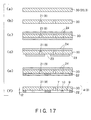
- Fig.17 is a view for explaining an eleventh example of a method for producing the ink-jetting recording head according to the invention.
- the eleventh example is for producing the ink-jetting recording head shown in Fig.16.
- a plate 30 into which a substrate 20 and a nozzle plate 3 are integrated is prepared.
- communication holes 21 (nozzles 8) are formed through the plate 30 by means of a pressing process, a dry-etching process, a laser-machining process or the like.
- a photosensitive resin 24 is applied onto both side surfaces of the substrate plate 30.
- the photosensitive resin is exposed and developed together with a conventional patterning (masking) tool , so that only a patterned portion 23 of a lower surface of the substrate plate 30 is exposed.
- the patterned portion 23 corresponds to walls of a flowing-path portion 22. Except for the patterned portion 23, the both side surfaces of the substrate plate 30 are masked.
- the substrate plate 30 is immersed in the electrocasting bath. Then, a direct-current voltage is applied to the electrocasting bath while using the substrate plate 30 as a cathode. Thus, as shown in Fig.17 (e), nickel or chromium is accumulated on the patterned portion 23 by electrocasting. Thus, the flowing-path portion 22 is formed.
- the photosensitive resin 24 is completely removed. Then, as shown in Fig.17 (f), the photosensitive resin 24 is completely removed. Then, the surface of the flowing-path portion 22 is ground so that a thickness t2 of the flowing-path portion 22 is adjusted to a predetermined uniform thickness. Thus, the flowing-path plate 4 integrated with the nozzle plate 3 is completed.
- Fig.18 is a view for explaining a twelfth example of a method for producing the ink-jetting recording head according to the invention.
- the twelfth example is also for producing the ink-jetting recording head shown in Fig.16.
- a plate 30 into which a substrate 20 and a nozzle plate 3 are integrated is prepared.
- a photosensitive resin 24 is applied onto both side surfaces of the substrate plate 30.
- the photosensitive resin is exposed and developed together with a conventional patterning (masking) tool, so that only a patterned portion 23 of a lower surface of the substrate plate 30 is exposed.
- the patterned portion 23 corresponds to walls of a flowing-path portion 22. Except for the patterned portion 23, the both side surfaces of the substrate plate 30 are masked.
- the substrate plate 30 is immersed in the electrocasting bath. Then, a direct-current voltage is applied to the electrocasting bath while using the substrate plate 30 as a cathode. Thus, as shown in Fig.18 (d), nickel or chromium is accumulated on the patterned portion 23 by electrocasting. Thus, the flowing-path portion 22 is formed.
- the photosensitive resin 24 is completely removed. Then, as shown in Fig.18 (e), the photosensitive resin 24 is completely removed. Then, the surface of the flowing-path portion 22 is ground so that a thickness t2 of the flowing-path portion 22 is adjusted to a predetermined uniform thickness. Thus, the flowing-path plate 4 integrated with the nozzle plate 3 is formed.
- communication holes 21 are formed through the flowing-path plate 4 by means of a pressing process, a dry-etching process, a laser-machining process or the like.
- Fig.19 shows a seventh embodiment of an ink-jetting recording head according to the invention.
- the nozzle plate 3 is formed by electrocasting on the flowing-path plate 4 that has been produced according to the method explained above with reference to Fig.2 or Fig.3.
- Other structure is substantially the same as the first embodiment shown in Fig.1.
- the same numeral references correspond to the same elements as the first embodiment. The explanation of the same elements is not repeated.
- the nozzle plate 3 may be mounted onto the flowing-path plate 4 during a continuous electrocasting step.
- the seventh embodiment can have substantially the same advantage as the first embodiment.
- Fig.20 is a view for explaining a thirteenth example of a method for producing the ink-jetting recording head according to the invention.
- the thirteenth example is for producing the ink-jetting recording head shown in Fig.19.
- a completed flowing-path plate 4 is prepared.
- a photosensitive resin 24 is applied onto a surface on a side of the substrate 20 of the flowing-path plate 4. Then, as shown in Fig.20 (c), the photosensitive resin 24 is exposed and developed together with a conventional patterning (masking) tool, so that only a first patterned photosensitive resin 24a remains for sealing the communication holes 21.
- a photosensitive resin 24' is applied onto the surface on the side of the substrate 20 of the flowing-path plate 4 over the first patterned photosensitive resin 24a. Then, as shown in Fig.20 (e), the photosensitive resin 24' is exposed and developed together with a conventional patterning (masking) tool, so that only a second patterned photosensitive resin 24b corresponding to the nozzles 8 remains on the first patterned photosensitive resin 24a.
- the flowing-path plate 4 is immersed in an electrocasting bath. Then, a direct-current voltage is applied to the electrocasting bath while using the flowing-path plate 4 as a cathode.
- nickel or chromium is accumulated by electrocasting on a portion corresponding to the nozzle plate that defines and surrounds the nozzles 8.
- the nozzle plate 3 is formed.
- the photosensitive resin 24a and 24b are completely removed. Then, as shown in Fig.20 (g), the photosensitive resin 24a and 24b are completely removed. Then, the surface of the nozzle plate 3 is ground so that a thickness t5 of the nozzle plate 3 is adjusted to a predetermined uniform thickness. Thus, the predetermined nozzle plate 3 is formed on the flowing-path plate 4.
- the nozzle plate 3 can be formed by electrocasting onto the flowing-path plate 4 at a state of Fig.3 (e), that is, before the communication holes 21 are formed.
- a state of Fig.3 (e) that is, before the communication holes 21 are formed.
- the electrocasting for the nozzle plate 3 and the electrocasting for the flowing-path portion 22 may be conducted at the same time.
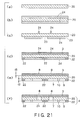
- Fig.21 is a view for explaining a fourteenth example of a method for producing the ink-jetting recording head according to the invention, wherein the electrocasting for the nozzle plate 3 and the electrocasting for the flowing-path portion 22 are conducted at the same time.
- the fourteenth example shown in Fig.21 is for producing the ink-jetting recording head shown in Fig.1.
- a substrate 20 is prepared.
- a photosensitive resin 24 is applied onto both side surfaces of the substrate 20.
- the photosensitive resin is exposed and developed together with a conventional patterning (masking) tool, so that a patterned portion 23 of a lower surface of the substrate 20 and a portion corresponding to the nozzle plate, which defines and surrounds the nozzles 8, of an upper surface of the substrate 20 are exposed.
- the patterned portion 23 corresponds to walls of a flowing-path portion 22. Except for the patterned portion 23 and the portion corresponding to the nozzle plate, the both side surfaces of the substrate 20 are masked.
- the substrate 20 is immersed in the electrocasting bath. Then, a direct-current voltage is applied to the electrocasting bath while using the substrate 20 as a cathode.
- a direct-current voltage is applied to the electrocasting bath while using the substrate 20 as a cathode.
- nickel or chromium is accumulated by electrocasting on the patterned portion 23 and the portion corresponding to the nozzle plate.
- the flowing-path portion 22 and the nozzle plate 3 are formed.
- the photosensitive resin 24 is completely removed. Then, as shown in Fig.21 (e), the photosensitive resin 24 is completely removed. Then, the surface of the flowing-path portion 22 is ground so that a thickness t2 of the flowing-path portion 22 is adjusted to a predetermined uniform thickness. Similarly, the surface of the nozzle plate 3 is ground so that a thickness t5 of the nozzle plate 3 is adjusted to a predetermined uniform thickness. Thus, the flowing-path plate 4 integrated with the nozzle plate 3 is formed.
- communication holes 21 are formed through the substrate 20 by means of a dry-etching process, a laser-machining process or the like.
- Figs.22A and 22B show an eighth embodiment of an ink-jetting recording head according to the invention.
- the ink-jetting recording head includes bending-vibration type of piezoelectric vibrating members 6A.
- Each of the piezoelectric vibrating members 6A is sandwiched between an upper electrode 16 and a lower electrode 17, and attached to the vibrating plate 5 of the flowing-path unit 1.
- the piezoelectric vibrating member 6A bends in a lateral direction thereof to change a pressure of the ink in the corresponding pressure chamber 7.
- the ink in the pressure chamber 7 may be jetted from the corresponding nozzle 8 as a drop of the ink.
- Other structure is substantially the same as the first embodiment shown in Fig.1.
- the same numeral references correspond to the same elements as the first embodiment. The explanation of the same elements is not repeated.
- the eighth embodiment can have substantially the same advantage as the first embodiment.
- Figs.23A shows a ninth embodiment of an ink-jetting recording head according to the invention.
- the ink-jetting recording head includes heaters 56 instead of the piezoelectric vibrating members.
- the flowing-path unit 1 includes a thermal conducive plate 55 instead of the vibrating plate.
- Each of the heaters 56 is attached to a portion of the thermal conductive plate 55 corresponding to each of the pressure chambers 7.
- the heater 56 when a driving signal is inputted to a heater 56, the heater 56 is heated to generate an air bubble in the ink in the corresponding pressure chamber 7. Because of further heating of the heater 56 or the like, the size of the air bubble may be controlled to change a pressure of the ink in the corresponding pressure chamber 7. Thus, the ink in the pressure chamber 7 may be jetted from the corresponding nozzle 8 as a drop of the ink.
- Other structure is substantially the same as the first embodiment shown in Fig.1.
- the same numeral references correspond to the same elements as the first embodiment. The explanation of the same elements is not repeated.
- the ninth embodiment can have substantially the same advantage as the first embodiment.
- Fig.23B shows a tenth embodiment of an ink-jetting recording head according to the invention.
- the ink-jetting recording head includes a silicon plate 65 instead of the thermal conductive plate.
- Each of the heaters 56 is attached to an upper surface of the silicon plate 65.
- the tenth embodiment can have substantially the same advantage as the ninth embodiment.
- a liquid may be glue, bonding agent, nail polish or the like, instead of the ink.
- the portion of the other side of the flowing-path plate is formed by electrocasting, a "warp" of the flowing-path plate may be prevented.
- the flowing-path plate may be formed more accurately.
- the portion formed by electrocasting includes at least a portion of the pressure-chamber space, preferably the whole pressure-chamber space, boundary walls defining the pressure-chamber space may have a relatively higher rigidity.
- the pressure-chamber spaces may be arranged more densely. Therefore, the liquid jetting head is advantageous in being made denser, made more accurate, and enlarged.
- the pressure-chamber space is formed as a portion of the flowing-path space, the pressure-chamber space may be easily positioned relative to the nozzle. Thus, it may be prevented that an air bubble is generated and stays in the flowing-path space. In addition, a step of peeling off the electrocasting portion is unnecessary, which is advantageous in cost.
Landscapes
- Engineering & Computer Science (AREA)
- Manufacturing & Machinery (AREA)
- Physics & Mathematics (AREA)
- Optics & Photonics (AREA)
- Particle Formation And Scattering Control In Inkjet Printers (AREA)
Applications Claiming Priority (2)
| Application Number | Priority Date | Filing Date | Title |
|---|---|---|---|
| JP2000010653 | 2000-01-19 | ||
| JP2000010653 | 2000-01-19 |
Publications (3)
| Publication Number | Publication Date |
|---|---|
| EP1118466A2 true EP1118466A2 (de) | 2001-07-25 |
| EP1118466A3 EP1118466A3 (de) | 2001-12-19 |
| EP1118466B1 EP1118466B1 (de) | 2006-06-21 |
Family
ID=18538648
Family Applications (1)
| Application Number | Title | Priority Date | Filing Date |
|---|---|---|---|
| EP01101132A Expired - Lifetime EP1118466B1 (de) | 2000-01-19 | 2001-01-19 | Flüssigkeitsausstosskopf |
Country Status (4)
| Country | Link |
|---|---|
| US (3) | US6631980B2 (de) |
| EP (1) | EP1118466B1 (de) |
| AT (1) | ATE330796T1 (de) |
| DE (1) | DE60120797T2 (de) |
Cited By (2)
| Publication number | Priority date | Publication date | Assignee | Title |
|---|---|---|---|---|
| EP1323532A3 (de) * | 2001-12-27 | 2003-09-03 | Seiko Epson Corporation | Flüssigkeitsausstosskopf und dazugehöriges Herstellungsverfahren |
| CN101152786B (zh) * | 2006-09-29 | 2010-06-23 | 兄弟工业株式会社 | 喷墨头 |
Families Citing this family (5)
| Publication number | Priority date | Publication date | Assignee | Title |
|---|---|---|---|---|
| WO2001072519A1 (en) | 2000-03-27 | 2001-10-04 | Fujitsu Limited | Multiple-nozzle ink-jet head and method of manufacture thereof |
| JPWO2006035773A1 (ja) | 2004-09-30 | 2008-05-15 | 日本碍子株式会社 | 液滴吐出圧電デバイス |
| DE602006014051D1 (de) * | 2005-04-28 | 2010-06-17 | Brother Ind Ltd | Verfahren zur Herstellung eines piezoelektrischen Aktors |
| US8205338B2 (en) * | 2009-08-20 | 2012-06-26 | Eastman Kodak Company | Method of making a multi-lobed nozzle |
| SG11201407801VA (en) * | 2012-05-31 | 2014-12-30 | Agency Science Tech & Res | Methods for use of mixed multifunctional surfaces for reducing aggregate content in protein preparations |
Citations (3)
| Publication number | Priority date | Publication date | Assignee | Title |
|---|---|---|---|---|
| JPH06305142A (ja) | 1993-04-23 | 1994-11-01 | Seiko Epson Corp | インクジェットヘッドおよびその製造方法 |
| JPH09123448A (ja) | 1995-10-31 | 1997-05-13 | Seiko Epson Corp | インクジェット式記録ヘッド、及びその製造方法 |
| JPH09300635A (ja) | 1996-05-13 | 1997-11-25 | Ricoh Co Ltd | インクジェット記録装置 |
Family Cites Families (22)
| Publication number | Priority date | Publication date | Assignee | Title |
|---|---|---|---|---|
| JPH05177834A (ja) | 1991-06-04 | 1993-07-20 | Seiko Epson Corp | インクジェット記録ヘッド |
| JPH05169666A (ja) * | 1991-12-25 | 1993-07-09 | Rohm Co Ltd | インクジェットプリントヘッドの製造方法 |
| JP3171213B2 (ja) | 1992-03-18 | 2001-05-28 | セイコーエプソン株式会社 | インクジェット式印字ヘッド |
| US5424769A (en) * | 1992-06-05 | 1995-06-13 | Seiko Epson Corporation | Ink jet recording head |
| US5896150A (en) * | 1992-11-25 | 1999-04-20 | Seiko Epson Corporation | Ink-jet type recording head |
| US5983471A (en) * | 1993-10-14 | 1999-11-16 | Citizen Watch Co., Ltd. | Method of manufacturing an ink-jet head |
| US5818482A (en) | 1994-08-22 | 1998-10-06 | Ricoh Company, Ltd. | Ink jet printing head |
| JPH0885212A (ja) | 1994-09-19 | 1996-04-02 | Ricoh Co Ltd | インクジェットヘッドのノズルプレート及びその製造方法 |
| JPH08142334A (ja) | 1994-11-25 | 1996-06-04 | Ricoh Co Ltd | インクジェット用ノズルプレートの製造方法 |
| JPH08169107A (ja) | 1994-12-19 | 1996-07-02 | Fujitsu Ltd | インクジェットヘッド |
| JPH08187863A (ja) | 1995-01-11 | 1996-07-23 | Canon Inc | インクジェット記録ヘッドのオリフィスプレートおよびその製造方法 |
| US5825386A (en) * | 1995-03-09 | 1998-10-20 | Brother Kogyo Kabushiki Kaisha | Piezoelectric ink-jet device and process for manufacturing the same |
| DE69629220T2 (de) | 1995-09-05 | 2004-04-15 | Seiko Epson Corp. | Tintenstrahlaufzeichunugskopf und sein Herstellungsverfahren |
| JP3627077B2 (ja) | 1995-12-08 | 2005-03-09 | 富士写真フイルム株式会社 | インクジェットプリンタ |
| EP1010532B1 (de) | 1996-04-04 | 2002-12-18 | Sony Corporation | Drucker und Verfahren zu seiner Herstellung |
| JP3241605B2 (ja) * | 1996-09-06 | 2001-12-25 | 松下電器産業株式会社 | 配線基板の製造方法並びに配線基板 |
| WO1998022288A1 (en) | 1996-11-18 | 1998-05-28 | Seiko Epson Corporation | Ink-jet recording head |
| EP2000307B1 (de) * | 1997-07-18 | 2013-09-11 | Seiko Epson Corporation | Tintenstrahlaufzeichnungskopf, Herstellungsverfahren dafür und Tintenstrahlaufzeichnungsvorrichtung |
| JPH11147317A (ja) | 1997-11-17 | 1999-06-02 | Fujitsu Ltd | ノズル板の製造方法 |
| JP2940544B1 (ja) | 1998-04-17 | 1999-08-25 | 日本電気株式会社 | インクジェット記録ヘッド |
| RU2151066C1 (ru) | 1998-11-03 | 2000-06-20 | Самсунг Электроникс Ко., Лтд. | Узел пластины сопла микроинжектора и способ его изготовления |
| DE60005111T2 (de) * | 1999-11-15 | 2004-03-25 | Seiko Epson Corp. | Tintenstrahldruckkopf und Tintenstrahlaufzeichnungsvorrichtung |
-
2001
- 2001-01-18 US US09/761,760 patent/US6631980B2/en not_active Expired - Fee Related
- 2001-01-19 EP EP01101132A patent/EP1118466B1/de not_active Expired - Lifetime
- 2001-01-19 AT AT01101132T patent/ATE330796T1/de not_active IP Right Cessation
- 2001-01-19 DE DE60120797T patent/DE60120797T2/de not_active Expired - Lifetime
-
2003
- 2003-08-06 US US10/634,923 patent/US6871400B2/en not_active Expired - Fee Related
-
2004
- 2004-12-10 US US11/008,296 patent/US6918658B2/en not_active Expired - Fee Related
Patent Citations (3)
| Publication number | Priority date | Publication date | Assignee | Title |
|---|---|---|---|---|
| JPH06305142A (ja) | 1993-04-23 | 1994-11-01 | Seiko Epson Corp | インクジェットヘッドおよびその製造方法 |
| JPH09123448A (ja) | 1995-10-31 | 1997-05-13 | Seiko Epson Corp | インクジェット式記録ヘッド、及びその製造方法 |
| JPH09300635A (ja) | 1996-05-13 | 1997-11-25 | Ricoh Co Ltd | インクジェット記録装置 |
Cited By (3)
| Publication number | Priority date | Publication date | Assignee | Title |
|---|---|---|---|---|
| EP1323532A3 (de) * | 2001-12-27 | 2003-09-03 | Seiko Epson Corporation | Flüssigkeitsausstosskopf und dazugehöriges Herstellungsverfahren |
| US7246888B2 (en) | 2001-12-27 | 2007-07-24 | Seiko Epson Corporation | Liquid jetting head and method of manufacturing the same |
| CN101152786B (zh) * | 2006-09-29 | 2010-06-23 | 兄弟工业株式会社 | 喷墨头 |
Also Published As
| Publication number | Publication date |
|---|---|
| US20040025344A1 (en) | 2004-02-12 |
| DE60120797T2 (de) | 2007-06-21 |
| EP1118466B1 (de) | 2006-06-21 |
| US20010015740A1 (en) | 2001-08-23 |
| EP1118466A3 (de) | 2001-12-19 |
| US6631980B2 (en) | 2003-10-14 |
| US20050104940A1 (en) | 2005-05-19 |
| DE60120797D1 (de) | 2006-08-03 |
| US6918658B2 (en) | 2005-07-19 |
| US6871400B2 (en) | 2005-03-29 |
| ATE330796T1 (de) | 2006-07-15 |
Similar Documents
| Publication | Publication Date | Title |
|---|---|---|
| US7867407B2 (en) | Method of manufacturing an ink-jet recording head | |
| US8458903B2 (en) | Method of producing an elastic plate member for a liquid jet head | |
| US20050012782A1 (en) | Inkjet head and a method of manufacturing the same | |
| EP0795404B1 (de) | Tintenstrahldruckkopf | |
| EP1118466B1 (de) | Flüssigkeitsausstosskopf | |
| EP0949079A1 (de) | Herstellungsverfahren für einen Tintenstrahldruckkopf | |
| EP1075389A1 (de) | Verfahren zur herstellung eines tintenstrahldruckkopfes | |
| JP4755105B2 (ja) | インクジェットプリントヘッド及びその製造プロセス | |
| JPH08174825A (ja) | インクジェット式記録ヘッド | |
| JPH10166572A (ja) | インクジェット式記録ヘッド | |
| JP3374899B2 (ja) | インクジェット式記録ヘッド、及びインクジェット式記録ヘッドの弾性板の製造方法 | |
| JP3419420B2 (ja) | インクジェット式記録ヘッド | |
| JP3452258B2 (ja) | 液体噴射ヘッド及びその製造方法 | |
| JPH0885212A (ja) | インクジェットヘッドのノズルプレート及びその製造方法 | |
| JP3114766B2 (ja) | インクジェットヘッドおよびその製造方法 | |
| JP2001130011A (ja) | インクジェットヘッド及びその製造方法並びにインクジェット式記録装置 | |
| JP2002067299A (ja) | インクジェット式記録ヘッド | |
| JPH1120159A (ja) | インクジェットヘッド部品及びその製造方法 | |
| JPH1034921A (ja) | インクジェット記録ヘッド、及びインクジェット記録ヘッド用弾性板の製造方法 | |
| JPH10138481A (ja) | インクジェットプリントヘッドおよびその製造方法 | |
| JP2000000967A (ja) | インクジェット式記録ヘッド、及びインクジェット式記録ヘッドの弾性板の製造方法 | |
| JPH1016215A (ja) | インクジェットヘッド及びその製造方法 | |
| HK1002953A (en) | Ink jet recording head |
Legal Events
| Date | Code | Title | Description |
|---|---|---|---|
| PUAI | Public reference made under article 153(3) epc to a published international application that has entered the european phase |
Free format text: ORIGINAL CODE: 0009012 |
|
| AK | Designated contracting states |
Kind code of ref document: A2 Designated state(s): AT BE CH CY DE DK ES FI FR GB GR IE IT LI LU MC NL PT SE TR |
|
| AX | Request for extension of the european patent |
Free format text: AL;LT;LV;MK;RO;SI |
|
| PUAL | Search report despatched |
Free format text: ORIGINAL CODE: 0009013 |
|
| AK | Designated contracting states |
Kind code of ref document: A3 Designated state(s): AT BE CH CY DE DK ES FI FR GB GR IE IT LI LU MC NL PT SE TR |
|
| AX | Request for extension of the european patent |
Free format text: AL;LT;LV;MK;RO;SI |
|
| 17P | Request for examination filed |
Effective date: 20020109 |
|
| AKX | Designation fees paid |
Free format text: AT BE CH CY DE DK ES FI FR GB GR IE IT LI LU MC NL PT SE TR |
|
| 17Q | First examination report despatched |
Effective date: 20050211 |
|
| GRAP | Despatch of communication of intention to grant a patent |
Free format text: ORIGINAL CODE: EPIDOSNIGR1 |
|
| GRAS | Grant fee paid |
Free format text: ORIGINAL CODE: EPIDOSNIGR3 |
|
| GRAA | (expected) grant |
Free format text: ORIGINAL CODE: 0009210 |
|
| AK | Designated contracting states |
Kind code of ref document: B1 Designated state(s): AT BE CH CY DE DK ES FI FR GB GR IE IT LI LU MC NL PT SE TR |
|
| PG25 | Lapsed in a contracting state [announced via postgrant information from national office to epo] |
Ref country code: AT Free format text: LAPSE BECAUSE OF FAILURE TO SUBMIT A TRANSLATION OF THE DESCRIPTION OR TO PAY THE FEE WITHIN THE PRESCRIBED TIME-LIMIT Effective date: 20060621 Ref country code: CH Free format text: LAPSE BECAUSE OF FAILURE TO SUBMIT A TRANSLATION OF THE DESCRIPTION OR TO PAY THE FEE WITHIN THE PRESCRIBED TIME-LIMIT Effective date: 20060621 Ref country code: FI Free format text: LAPSE BECAUSE OF FAILURE TO SUBMIT A TRANSLATION OF THE DESCRIPTION OR TO PAY THE FEE WITHIN THE PRESCRIBED TIME-LIMIT Effective date: 20060621 Ref country code: NL Free format text: LAPSE BECAUSE OF FAILURE TO SUBMIT A TRANSLATION OF THE DESCRIPTION OR TO PAY THE FEE WITHIN THE PRESCRIBED TIME-LIMIT Effective date: 20060621 Ref country code: BE Free format text: LAPSE BECAUSE OF FAILURE TO SUBMIT A TRANSLATION OF THE DESCRIPTION OR TO PAY THE FEE WITHIN THE PRESCRIBED TIME-LIMIT Effective date: 20060621 Ref country code: LI Free format text: LAPSE BECAUSE OF FAILURE TO SUBMIT A TRANSLATION OF THE DESCRIPTION OR TO PAY THE FEE WITHIN THE PRESCRIBED TIME-LIMIT Effective date: 20060621 Ref country code: IT Free format text: LAPSE BECAUSE OF FAILURE TO SUBMIT A TRANSLATION OF THE DESCRIPTION OR TO PAY THE FEE WITHIN THE PRESCRIBED TIME-LIMIT;WARNING: LAPSES OF ITALIAN PATENTS WITH EFFECTIVE DATE BEFORE 2007 MAY HAVE OCCURRED AT ANY TIME BEFORE 2007. THE CORRECT EFFECTIVE DATE MAY BE DIFFERENT FROM THE ONE RECORDED. Effective date: 20060621 |
|
| REG | Reference to a national code |
Ref country code: GB Ref legal event code: FG4D |
|
| REG | Reference to a national code |
Ref country code: CH Ref legal event code: EP |
|
| REG | Reference to a national code |
Ref country code: IE Ref legal event code: FG4D |
|
| REF | Corresponds to: |
Ref document number: 60120797 Country of ref document: DE Date of ref document: 20060803 Kind code of ref document: P |
|
| PG25 | Lapsed in a contracting state [announced via postgrant information from national office to epo] |
Ref country code: SE Free format text: LAPSE BECAUSE OF FAILURE TO SUBMIT A TRANSLATION OF THE DESCRIPTION OR TO PAY THE FEE WITHIN THE PRESCRIBED TIME-LIMIT Effective date: 20060921 Ref country code: DK Free format text: LAPSE BECAUSE OF FAILURE TO SUBMIT A TRANSLATION OF THE DESCRIPTION OR TO PAY THE FEE WITHIN THE PRESCRIBED TIME-LIMIT Effective date: 20060921 |
|
| PG25 | Lapsed in a contracting state [announced via postgrant information from national office to epo] |
Ref country code: ES Free format text: LAPSE BECAUSE OF FAILURE TO SUBMIT A TRANSLATION OF THE DESCRIPTION OR TO PAY THE FEE WITHIN THE PRESCRIBED TIME-LIMIT Effective date: 20061002 |
|
| PG25 | Lapsed in a contracting state [announced via postgrant information from national office to epo] |
Ref country code: PT Free format text: LAPSE BECAUSE OF FAILURE TO SUBMIT A TRANSLATION OF THE DESCRIPTION OR TO PAY THE FEE WITHIN THE PRESCRIBED TIME-LIMIT Effective date: 20061121 |
|
| NLV1 | Nl: lapsed or annulled due to failure to fulfill the requirements of art. 29p and 29m of the patents act | ||
| REG | Reference to a national code |
Ref country code: CH Ref legal event code: PL |
|
| ET | Fr: translation filed | ||
| PG25 | Lapsed in a contracting state [announced via postgrant information from national office to epo] |
Ref country code: IE Free format text: LAPSE BECAUSE OF NON-PAYMENT OF DUE FEES Effective date: 20070119 |
|
| PG25 | Lapsed in a contracting state [announced via postgrant information from national office to epo] |
Ref country code: MC Free format text: LAPSE BECAUSE OF NON-PAYMENT OF DUE FEES Effective date: 20070131 |
|
| PLBE | No opposition filed within time limit |
Free format text: ORIGINAL CODE: 0009261 |
|
| STAA | Information on the status of an ep patent application or granted ep patent |
Free format text: STATUS: NO OPPOSITION FILED WITHIN TIME LIMIT |
|
| 26N | No opposition filed |
Effective date: 20070322 |
|
| PG25 | Lapsed in a contracting state [announced via postgrant information from national office to epo] |
Ref country code: GR Free format text: LAPSE BECAUSE OF FAILURE TO SUBMIT A TRANSLATION OF THE DESCRIPTION OR TO PAY THE FEE WITHIN THE PRESCRIBED TIME-LIMIT Effective date: 20060922 |
|
| PG25 | Lapsed in a contracting state [announced via postgrant information from national office to epo] |
Ref country code: CY Free format text: LAPSE BECAUSE OF FAILURE TO SUBMIT A TRANSLATION OF THE DESCRIPTION OR TO PAY THE FEE WITHIN THE PRESCRIBED TIME-LIMIT Effective date: 20060621 Ref country code: LU Free format text: LAPSE BECAUSE OF NON-PAYMENT OF DUE FEES Effective date: 20070119 |
|
| PG25 | Lapsed in a contracting state [announced via postgrant information from national office to epo] |
Ref country code: TR Free format text: LAPSE BECAUSE OF FAILURE TO SUBMIT A TRANSLATION OF THE DESCRIPTION OR TO PAY THE FEE WITHIN THE PRESCRIBED TIME-LIMIT Effective date: 20060621 |
|
| PGFP | Annual fee paid to national office [announced via postgrant information from national office to epo] |
Ref country code: FR Payment date: 20120202 Year of fee payment: 12 |
|
| PGFP | Annual fee paid to national office [announced via postgrant information from national office to epo] |
Ref country code: DE Payment date: 20120111 Year of fee payment: 12 |
|
| PGFP | Annual fee paid to national office [announced via postgrant information from national office to epo] |
Ref country code: GB Payment date: 20120118 Year of fee payment: 12 |
|
| GBPC | Gb: european patent ceased through non-payment of renewal fee |
Effective date: 20130119 |
|
| REG | Reference to a national code |
Ref country code: FR Ref legal event code: ST Effective date: 20130930 |
|
| PG25 | Lapsed in a contracting state [announced via postgrant information from national office to epo] |
Ref country code: DE Free format text: LAPSE BECAUSE OF NON-PAYMENT OF DUE FEES Effective date: 20130801 |
|
| REG | Reference to a national code |
Ref country code: DE Ref legal event code: R119 Ref document number: 60120797 Country of ref document: DE Effective date: 20130801 |
|
| PG25 | Lapsed in a contracting state [announced via postgrant information from national office to epo] |
Ref country code: FR Free format text: LAPSE BECAUSE OF NON-PAYMENT OF DUE FEES Effective date: 20130131 Ref country code: GB Free format text: LAPSE BECAUSE OF NON-PAYMENT OF DUE FEES Effective date: 20130119 |