EP1118563B1 - Greifersystem mit verstellbarer Geschwindigkeit - Google Patents
Greifersystem mit verstellbarer Geschwindigkeit Download PDFInfo
- Publication number
- EP1118563B1 EP1118563B1 EP00127209A EP00127209A EP1118563B1 EP 1118563 B1 EP1118563 B1 EP 1118563B1 EP 00127209 A EP00127209 A EP 00127209A EP 00127209 A EP00127209 A EP 00127209A EP 1118563 B1 EP1118563 B1 EP 1118563B1
- Authority
- EP
- European Patent Office
- Prior art keywords
- gripper
- arm
- housing
- arms
- gripper system
- Prior art date
- Legal status (The legal status is an assumption and is not a legal conclusion. Google has not performed a legal analysis and makes no representation as to the accuracy of the status listed.)
- Expired - Lifetime
Links
Images


Classifications
-
- B—PERFORMING OPERATIONS; TRANSPORTING
- B65—CONVEYING; PACKING; STORING; HANDLING THIN OR FILAMENTARY MATERIAL
- B65G—TRANSPORT OR STORAGE DEVICES, e.g. CONVEYORS FOR LOADING OR TIPPING, SHOP CONVEYOR SYSTEMS OR PNEUMATIC TUBE CONVEYORS
- B65G17/00—Conveyors having an endless traction element, e.g. a chain, transmitting movement to a continuous or substantially-continuous load-carrying surface or to a series of individual load-carriers; Endless-chain conveyors in which the chains form the load-carrying surface
- B65G17/30—Details; Auxiliary devices
- B65G17/32—Individual load-carriers
- B65G17/323—Grippers, e.g. suction or magnetic
-
- B—PERFORMING OPERATIONS; TRANSPORTING
- B65—CONVEYING; PACKING; STORING; HANDLING THIN OR FILAMENTARY MATERIAL
- B65H—HANDLING THIN OR FILAMENTARY MATERIAL, e.g. SHEETS, WEBS, CABLES
- B65H29/00—Delivering or advancing articles from machines; Advancing articles to or into piles
- B65H29/003—Delivering or advancing articles from machines; Advancing articles to or into piles by grippers
-
- B—PERFORMING OPERATIONS; TRANSPORTING
- B65—CONVEYING; PACKING; STORING; HANDLING THIN OR FILAMENTARY MATERIAL
- B65H—HANDLING THIN OR FILAMENTARY MATERIAL, e.g. SHEETS, WEBS, CABLES
- B65H2403/00—Power transmission; Driving means
- B65H2403/50—Driving mechanisms
- B65H2403/51—Cam mechanisms
- B65H2403/513—Cam mechanisms involving elongated cam, i.e. parallel to linear transport path
-
- B—PERFORMING OPERATIONS; TRANSPORTING
- B65—CONVEYING; PACKING; STORING; HANDLING THIN OR FILAMENTARY MATERIAL
- B65H—HANDLING THIN OR FILAMENTARY MATERIAL, e.g. SHEETS, WEBS, CABLES
- B65H2403/00—Power transmission; Driving means
- B65H2403/50—Driving mechanisms
- B65H2403/53—Articulated mechanisms
- B65H2403/531—Planar mechanisms
- B65H2403/5311—Parallelogram mechanisms
-
- B—PERFORMING OPERATIONS; TRANSPORTING
- B65—CONVEYING; PACKING; STORING; HANDLING THIN OR FILAMENTARY MATERIAL
- B65H—HANDLING THIN OR FILAMENTARY MATERIAL, e.g. SHEETS, WEBS, CABLES
- B65H2403/00—Power transmission; Driving means
- B65H2403/50—Driving mechanisms
- B65H2403/53—Articulated mechanisms
- B65H2403/533—Slotted link mechanism
- B65H2403/5333—Slotted link mechanism with oscillating slotted link
Definitions
- the present invention relates to a gripper system with a movable gripper unit and a method for Gripping printed products according to the preambles of claims 1 and 20.
- a gripper system with the features of the generic term of claim 1 is from US-B-5,901,997 known.
- a gripper unit comprises a housing, a first gripper arm and a second gripper arm for detecting a printed product, wherein the first and second Gripper arm are displaceable relative to the housing.
- the housing is preferably along a guide rail movable.
- the Speed of the print product held by the gripper arms with respect to Speed of the housing to be changed. This speed change can take place while the printed product is held by the gripper arms.
- each of the gripper arms is each attached to a separate bar, wherein each of the bars is attached at its ends to a sliding carriage which slides in a recess formed in one side of the housing is displaceable.
- the case has preferably the shape of an inverted U.
- the first rod is preferably on one End stationary with respect to the carriage and the second rod is preferably rotatable, so that he can move the second gripper arm such that this second gripper arm moved and a printed product is taken against the rotationally fixed first arm.
- the rotatable second gripper arm is preferably at one end with respect to the carriage biased so that the second gripper arm is moved to an open position.
- the second rod By one connected to the rotatable second rod and one of the carriages Lever, the second rod is movable against the spring force, so that the second Gripper arm takes the printed product.
- a cam can be in its end position be determined so that the lever is held in a closed position.
- Of the Lever can be detected by means of a bolt in the closed position, wherein a rotation of the second rod is prevented back into the open position.
- the product can be released as the second Bar acting biasing force the second gripper arm in an open position emotional.
- a cam may be provided which is provided with a preferably V-shaped, two-armed hinge is connected.
- One arm of the hinge is preferably laterally on Housing attached and another arm is connected to the sliding carriage.
- a curve can act on the cam in such a way that the V-shaped hinge is flattened and so the sliding carriage in the recess with respect to the Housing is moved.
- the hinge can be detected in its end position.
- each Side of the gripper unit preferably comprises a gripper / hinge arrangement.
- Another embodiment of the present invention includes a Gripper device with a guide rail and a plurality of in the Guide rail running gripper units.
- Each of the gripper units includes a Housing, a first gripper arm and a second gripper arm for detecting a Printed product, wherein the first and second gripper arm with respect to the housing are displaceable.
- the gripper device may further comprise a chain drive for driving the Include gripper units with preferably constant speed.
- a curve can be provided, by means of which the gripper arms of a respective gripper unit with respect of the housing are displaceable. This is the speed of the printed product changeable while the printed product is being held.
- the curve can with a Cam interact, which is connected to a sliding carriage, in the gripper arms are mounted in the housing.
- the inventive method for gripping printed products is a Gripped printed product in a gripper unit and moved relative to the gripper unit, while ensuring a secure hold of the printed product in the gripper.
- the Printed products are preferably detected by two gripper arms, which in a Recess to be moved in a housing.
- the shift can be, for example be effected by means of a curve arrangement.
- the second gripper arm of the gripper unit is preferably rotatable, the method further provides that the second gripper arm in the closed position by means of a Riegel is determined and that the bar is released to release the product.
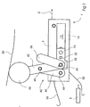
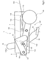
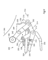
- Fig. 1 is a running in a guide rail or track 2 gripper unit. 1 shown, the z. B. by a running at a uniform speed chain is driven.
- the gripper unit 1 comprises a housing 3 with a first side 10 and a second side 110 (see Fig. 4).
- the housing 3 may, for. B. in the form of an inverted U be educated.
- the first side 10 has a recess 12 in which a carriage 14 is displaceable forward and backward.
- the gripper unit 1 comprises for detecting a Print product 5 a first gripper arm 20 and a second gripper arm 30.
- the first Gripper arm 20 is fixed relative to the carriage 14 and z. B. on a rod 22 fixed, which firmly with another carriage in a recess on the second Side (110) of the housing 3 is connected.
- the second gripper arm 30 is fixedly attached to a rod 32 which is rotatable in the carriage 14 is stored.
- the second gripper arm 30 is with respect to the carriage 14 with a spring force acted upon, so that the gripper arm 30 in the direction indicated by the arrow 34 Direction turns and is moved in this way in an open position, as in Fig. 1st is shown.
- a lever 36 On the rod 32, a lever 36 is attached.
- An arm 42 of a V-shaped Hinge 40 is rotatable on the rod 32 and via a pin 45 on a second arm 44 of the Hinge 40 attached.
- the second arm is pivotally connected to the housing 3 via a pin 48 attached.
- a cam 46 is attached.
- the second gripper arm 30 Since the second gripper arm 30 is fixedly secured to the rod 32, the second gripper arm rotates 30 in the direction indicated by the arrow 39 downward direction.
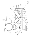
- the curve 50 causes a downward movement of the cam 46, so that the hinge 40 is detected at the center line 60.
- the carriage 14 is in the foremost position in the recess 12.
- One end of the carriage 14th can protrude from the housing 3 on the inside of the recess 12.
- the Forward movement of the carriage 14 is by a with the end of the recess 12th cooperating stage 15 (see Fig. 2) limited.
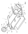
- FIG. 4 shows a perspective view of the gripper unit 1 according to FIG. 3.
- the Housing 3 comprises a first side 10, a second side 110 and a top 11, which on the guide rail 2 shown schematically can run.
- the second side 110 includes a recess 112 in which a carriage may be slidably received.
- a Cam 146 is on a V-shaped hinge 140 with a first arm 142 and a second arm 144 arranged.
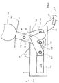
- FIG. 5 the side of the gripper unit 1 opposite the side shown in FIG. 3 is shown shown.
- the second hinge 140 is connected through a second, on a cam 146th acting curve 150 detected in its final position.
- the arm 144 of the hinge 140 is rotatably connected to a pin 148 and a pin 145.
- the arm 142 of the hinge 140 is connected to the pin 145 and the rod 32.
- a latch 136 is rotatably attached to the carriage 114 via a pin 137, that it can exert a clockwise directed force around the pin 137.
- These clockwise directed force can z. B. generated by a spring or in that the center of gravity of the bolt 136 is always arranged behind the pin 137.
- the gripper unit 1 can therefore preferably at constant speed along the Guide rail 2 are guided while holding a printed product 5.
- the curves act 50 on the cams 46 and 146 and thus cause a displacement of the carriage 14 and 114 with respect to the housing 3, which continues to move at a constant speed can be.
- a Movement of the gripper arms in the forward or reverse direction offers some advantages; z. B. the need for separate braking devices for Deceleration of printed products is reduced or eliminated altogether.
- the respective cam moved through the curve to the top position.
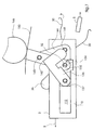
- the curve moves 150, the cam 146 upwards, wherein the latch 136 in the direction of the pin 148th is moved.
- the printed product 5 is still detected by the gripper unit.
- the cam 146 is relative to the upper edge of the housing 3 in a even higher position, so that by the interaction of the bolt 136 with the pin 148, the rod 32 and the stepped recess 132 are rotated and the rod 32nd is released.
- the rod 32 together with the lever 36 and the second Gripper arm 30 is rotated, as indicated by the arrow 135.
- the printed product 5 is released in this way by the gripper unit 1 and can for example, stored on a conveyor belt or to a further gripper device be handed over.
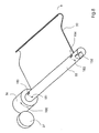
- Fig. 8 shows a schematic representation of a possible embodiment of the rod 32, the Adjusting lever 36 and the second gripper arm 30, which are all firmly connected.
- the adjusting pin 37 can act on the lever 36, wherein against the arrows 181 and 182 indicated spring force a rotational movement of the lever 36 in the direction of the arrow 180 is triggered.
- the rod 32 preferably includes two slots 183 and 184, in FIG which z. B. leaf springs for generating the spring force can be added. The other ends of the leaf springs may be fixed to the housing 3 (see Fig. 4). The in the bar 32 introduced step-shaped recess 132 can also be seen.
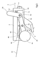
- Fig. 9 is a side view of a second embodiment of a device according to the invention Gripper unit 200.
- the gripper unit 200 comprises a housing 203 with prongs 204 and 205 (see Fig. 11).
- the housing 203 comprises two roller surfaces 223 and 224 on which a roller 208 and a roller 213 (Fig. 12) is movable.
- the gripper units 200 run in a guide rail 201, wherein the top of the housing 203 z. B. at one in the guide rail 201 attached to the running chain.
- the gripper comprises 200 a first gripper arm 220 and a second gripper arm 230 for detecting a Printed product.
- the first gripper arm 220 is held by rollers 206 which run along the Prongs 204, 205 can roll, so that the gripper arm 220 with respect to the housing 203 is displaceable.
- the second gripper arm 230 is rotatable about the pivot point or pin 212 Arm 220 connected.
- a schematically illustrated cup spring assembly 210 holds the Arm 230 in the open position, when the arm 220 in a rear (in Fig. 9 left) position is.
- the other end of the spring is attached to an arm 209 which connected at one end to the roller 208 and at the other end to the pin 212.
- the spring 210 may be disposed on the inside of the arm 230, but here is off For clarity, shown on the outside.
- the arm 230 is rotatably mounted with respect to the arm 220 about the pin 212, which also with one end of an arm 214 is connected.
- the other end of the arm 214 is above a Pivot 232 is connected to a lever 242 which rotates about one in the housing 203 mounted rod 245 is rotatable.
- a cam 246 At one end of the lever 242 is a cam 246 arranged, which can be actuated by a curve 250.
- the curve 250 moves the cam 246 downwards, that at one end of the arm 214 mounted roller 213 along the roller surface 224 in the by the arrow 215th indicated upward direction moves.
- the pin 212 is moved by the arm 214 pulled in the direction indicated by the arrow 216 forward direction, whereby the Gripper arms 220 and 230 slide forward so that the rollers 206 on the tines 204, Roll forward 205 times.
- the arm 209 is also pulled forward by the pin 212, so the roller 208 rolls along the roller surface 223 and, as shown in FIG. 9, is moved downwards.
- the tension of the spring 210 accordingly decreases, and the arm 230 is moved downwards so that between the arms 220 and 230 detects a printed product becomes.
- the roller 213 can be detected in the detection position by the roller 213 remains over a bent position in the surface 224. To release the product a curve may be provided through which the cam 246 upwards and the Roller 213 is moved down.
- the second embodiment is preferable to the first insofar as no bolts are needed and the displacement is caused by rolling, which reduces the friction becomes.
- the term "gripper arm” as used herein includes those in the drawings shown bent sheets any arrangement that is suitable for detecting Print products is suitable.
- a “sled” in the sense of this Registration is any movable element.
- a “shift” is as one defining sliding relative motion between two elements, which is also a Roll arrangement includes.
Landscapes
- Engineering & Computer Science (AREA)
- Mechanical Engineering (AREA)
- Discharge By Other Means (AREA)
- Manipulator (AREA)
- Feeding Of Articles By Means Other Than Belts Or Rollers (AREA)
- Vehicle Body Suspensions (AREA)
- Forklifts And Lifting Vehicles (AREA)
- Gripping On Spindles (AREA)
Description
- Fig. 1
- eine erste Seite einer ersten Ausführungsform einer entlang einer Führungsschiene geführten erfindungsgemäßen Greifereinheit in einer geöffneten Position;
- Fig. 2
- eine erste Seite der in Fig. 1 gezeigten Greifereinheit, bei der sich die Greiferarme bezüglich des Gehäuses in einer vorwärts bewegten Position befinden;
- Fig. 3
- eine erste Seite der in Fig. 1 gezeigten Greifereinheit, bei der die Greiferarme in der geschlossenen Position festgestellt sind;
- Fig. 4
- eine perspektivische Darstellung der Greifereinheit nach Fig. 2;
- Fig. 5
- eine zweite Seite der Greifereinheit nach Fig. 3;
- Fig. 6
- eine zweite Seite der Greifereinheit, deren Greiferarme in den hinteren Bereich des Gehäuses der Greifereinheit bewegt sind;
- Fig. 7
- die Greifereinheit nach Fig. 6 mit geöffneten Greiferarmen;
- Fig. 8
- eine schematische Darstellung des zweiten Greiferarms und des Stabs der Greifereinheit in der ersten Ausführungsform;
- Fig. 9
- eine Seitenansicht einer zweiten Ausführungsform einer erfindungsgemäßen Greifereinheit;
- Fig. 10
- eine perspektivische Darstellung des hinteren und seitlichen Abschnitts der zweiten Ausführungsform;
- Fig. 11
- eine perspektivische Draufsicht der Greifereinheit nach Fig. 9;
- Fig. 12
- eine perspektivische Vorderansicht der Greifereinheit nach Fig. 9;
- Fig. 13
- die zweite Ausführungsform der Greifereinheiten in einer Führungsschiene; und
- Fig. 14
- die zweite Ausführungsform der Greifereinheiten in einer Führungsschiene;
- 1
- Greifereinheit
- 2
- Führungsschiene
- 3
- Gehäuse
- 5
- Druckprodukt
- 6
- Verschiebungsrichtung
- 10
- erste Seite
- 11
- Oberseite
- 12
- Aussparung
- 14
- Schlitten
- 20
- Greiferarm
- 22
- Stab
- 30
- Greiferarm
- 32
- Stab
- 34
- Drehrichtung
- 34
- Richtung der Federkraft
- 35
- Richtung
- 36
- Stellhebel
- 37
- Stellstift
- 39
- Drehrichtung
- 40
- Scharnier
- 42
- erster Arm
- 44
- zweiter Arm
- 45
- Stift
- 46
- Kurvenscheibe
- 48
- Stift
- 50
- Kurve
- 60
- Mittellinie
- 110
- zweite Seite
- 112
- Aussparung
- 114
- Schlitten
- 132
- stufenförmige Ausnehmung
- 133
- Bewegungsrichtung
- 136
- Riegel
- 137
- Stift
- 140
- Scharnier
- 142
- erster Arm
- 144
- zweiter Arm
- 145
- Stift
- 146
- Kurvenscheibe
- 148
- Stift
- 150
- Kurve
- 180
- Drehrichtung
- 181
- Richtung der Federkraft
- 182
- Richtung der Federkraft
- 183
- Schlitz
- 184
- Schlitz
- 200
- Greifereinheit
- 201
- Führungsschiene
- 203
- Gehäuse
- 204
- Zinken
- 205
- Zinken
- 206
- Walzen
- 208
- Walze
- 209
- Arm
- 210
- Feder
- 212
- Stift
- 213
- Walze
- 214
- Arm
- 216
- Richtung
- 220
- erster Greiferarm
- 223
- Walzenfläche
- 224
- Walzenfläche
- 230
- zweiter Greiferarm
- 232
- Schwenkpunkt
- 242
- Hebel
- 245
- Stange
- 246
- Kurvenscheibe
- 250
- Kurve
Claims (22)
- Greifersystem mitder erste Greiferarm (20, 220) und der zweite Greiferarm (30, 230) relativ zum Gehäuse (3, 203) verschiebbar sind,einer Führungsbahn (2, 201) undeiner in der Führungsbahn entlang einer Vorwärtsrichtung bewegbaren Greifereinheit (1, 200) mit einem Gehäuse (3, 203), einem ersten Greiferarm (20, 220) und einem zweiten Greiferarm (30, 230), wobei
dadurch gekennzeichnet, dass der erste Greiferarm (20,220) und der zweite Greiferarm (30, 230) zum Erfassen eines Druckprodukts (5) geeignet sind, und
dass der erste (20, 220) und der zweite Greiferarm (30, 230) in Vorwärts- und in Rückwärtsrichtung verschiebbar sind. - Greifersystem nach Anspruch 1,
dadurch gekennzeichnet, dass das Gehäuse (3) eine erste Aussparung (12) und eine zweite Aussparung (112) umfasst und ein erster Schlitten (14) in der ersten Aussparung (12) verschiebbar angeordnet ist und ein zweiter Schlitten (114) in der zweiten Aussparung (112) verschiebbar angeordnet ist, wobei der erste und der zweite Greiferarm (20, 30) mit dem ersten und zweiten Schlitten (14, 114) verbunden sind. - Greifersystem nach Anspruch 2,
gekennzeichnet durch
einen ersten Stab (22), mit dem der erste Greiferarm (20) fest verbunden ist und der drehfest zwischen dem ersten und zweiten Schlitten (14, 114) gelagert ist. - Greifersystem nach Anspruch 2,
gekennzeichnet durch
einen drehbaren Stab (32), der drehbar zwischen dem ersten und zweiten Schlitten (14, 114) gelagert ist und mit dem der zweite Greiferarm (30) fest verbunden ist. - Greifersystem nach Anspruch 4,
dadurch gekennzeichnet, dass der drehbare Stab (32) bezüglich des ersten und zweiten Schlittens (14, 114) federgespannt ist. - Greifersystem nach einem der Ansprüche 2 bis 5,
gekennzeichnet durch
einen Riegel (136) zum Feststellen des drehbaren Stabs (32). - Greifersystem nach einem der Ansprüche 1 bis 6,
dadurch gekennzeichnet, dass das Gehäuse (3) die Form eines umgedrehten U hat. - Greifersystem nach einem der Ansprüche 2 bis 7,
gekennzeichnet durch
ein Scharnier (40) zum Bewegen der Schlitten (14, 114), dessen eines Ende (42) mit dem Schlitten (14, 114) und dessen anderes Ende (44) mit dem Gehäuse (3) verbunden ist. - Greifersystem nach Anspruch 8,
dadurch gekennzeichnet, dass am Scharnier (40) eine Kurvenscheibe (46) befestigt ist. - Greifersystem nach Anspruch 1,
dadurch gekennzeichnet, dass zum Verschieben des ersten und zweiten Greiferarms (20, 30, 220, 230) bezüglich des Gehäuses (3, 203) eine Kurvenscheibe (46, 146, 246) mit dem ersten und zweiten Greiferarm (20, 30, 220, 230) verbunden ist. - Greifersystem nach Anspruch 1,
dadurch gekennzeichnet dass zum Schließen des zweiten Greiferarms (30) in Richtung des ersten Greiferarms (20) ein Stellhebel (36) mit dem ersten und zweiten Greiferarm (20, 30) verbundenen ist. - Greifersystem nach Anspruch 1,
dadurch gekennzeichnet, dass der erste Greiferarm (20) drehfest ist und der zweite Greiferarm (30) drehbar ist. - Greifersystem nach Anspruch 1,
dadurch gekennzeichnet, dass der erste Greiferarm (220) mit mindestens einer Walze (206) verbunden ist und dass das Gehäuse (203) mindestens einen Zinken (204, 205) umfasst, auf dem die Walze (206) abrollt. - Greifersystem nach Anspruch 13,
dadurch gekennzeichnet, dass der zweite Greiferarm (230) über einen Stift (212) mit dem ersten Greiferarm (220) verbunden ist und in eine geöffnete Position vorgespannt ist. - Greifersystem nach Anspruch 14,
dadurch gekennzeichnet, dass der Stift (212) mit einer Kurvenscheibe (246) verbunden ist, die den Stift (212) bewegt. - Greifersystem nach Anspruch 15,
dadurch gekennzeichnet, dass der Stift (212) mit einem Arm (209) verbunden ist, der mit einer Feder (210) verbunden ist, die auch mit dem zweiten Greiferarm (230) verbunden ist. - Greifersystem nach einem der Ansprilche 1 bis 16,
dadurch gekennzeichnet, dass eine Vielzahl von Greifereinheiten (1, 200) vorgesehen sind, die in der Führungsschiene (2, 201) laufen. - Greifersystem nach Anspruch 17,
dadurch gekennzeichnet, dass jede Greifereinheit (1, 200) eine mit dem ersten und zweiten Greiferarm (20, 30, 220, 230) verbundene Kurvenscheibe (46, 146, 246) umfasst, mittels derer der erste und zweite Greiferarm (20, 30, 220, 230) bezüglich des Gehäuses (3, 203) verschiebbar ist. - Greifersystem nach Anspruch 18,
dadurch gekennzeichnet, dass zur Kooperation mit der Kurvenscheibe (46, 146, 246) eine Kurve (50, 250) vorgesehen ist. - Verfahren zum Greifen von Druckprodukten,
dadurch gekennzeichnet, dass ein Druckprodukt (5) in einer Greifereinheit (1, 200) eines Greifersystems nach einem der Ansprüche 1 bis 19 ergriffen und dann das Druckprodukt (5) während des Weitertransports relativ zur Greifereinheit (1, 200) bewegt wird. - Verfahren nach Anspruch 20,
dadurch gekennzeichnet, dass das Ergreifen mittels eines Greiferarm-Paars (20, 30, 220, 230) erfolgt und die beiden Greiferarme (20, 30, 220, 230) bezüglich der Greifereinheit (1, 200) bewegt werden. - Verfahren nach einem der Ansprüche 20 bis 21,
dadurch gekennzeichnet, dass die Greifereinheit (1, 200) mit gleichmäßiger Geschwindigkeit bewegt wird und das Druckprodukt (5) abgebremst wird, während es bewegt wird.
Applications Claiming Priority (2)
| Application Number | Priority Date | Filing Date | Title |
|---|---|---|---|
| US488254 | 2000-01-20 | ||
| US09/488,254 US6357741B1 (en) | 2000-01-20 | 2000-01-20 | Velocity adjustable grippers on sliding carriage |
Publications (3)
| Publication Number | Publication Date |
|---|---|
| EP1118563A2 EP1118563A2 (de) | 2001-07-25 |
| EP1118563A3 EP1118563A3 (de) | 2003-06-18 |
| EP1118563B1 true EP1118563B1 (de) | 2005-12-07 |
Family
ID=23938970
Family Applications (1)
| Application Number | Title | Priority Date | Filing Date |
|---|---|---|---|
| EP00127209A Expired - Lifetime EP1118563B1 (de) | 2000-01-20 | 2000-12-14 | Greifersystem mit verstellbarer Geschwindigkeit |
Country Status (5)
| Country | Link |
|---|---|
| US (1) | US6357741B1 (de) |
| EP (1) | EP1118563B1 (de) |
| JP (1) | JP4723099B2 (de) |
| AT (1) | ATE312040T1 (de) |
| DE (2) | DE10061703B4 (de) |
Families Citing this family (10)
| Publication number | Priority date | Publication date | Assignee | Title |
|---|---|---|---|---|
| DE10152843A1 (de) * | 2000-11-29 | 2002-06-13 | Heidelberger Druckmasch Ag | Vorrichtung zur Anpassung der Lage bogenförmigen Material bei Bewegungsrichtungsumkehr |
| US6511065B1 (en) * | 2001-08-28 | 2003-01-28 | Heidelberger Druckmaschinen Ag | Method for transferring signatures and gripper assembly for a matched velocity transfer device |
| TWI261042B (en) * | 2003-10-08 | 2006-09-01 | Bobst Sa | Working station of a machine processing plate elements |
| US7530564B2 (en) * | 2006-07-10 | 2009-05-12 | Goss International Americas, Inc. | Opposing link gripper |
| US7694949B2 (en) * | 2006-09-18 | 2010-04-13 | Goss International Americas, Inc | Custodial lapped stream mechanism |
| DE102009001189A1 (de) * | 2009-02-26 | 2010-09-02 | Koenig & Bauer Aktiengesellschaft | Auslagevorrichtung einer bogenverarbeitenden Maschine mit einem Bogenfördersystem zum Fördern der Bogen |
| DE202010002890U1 (de) * | 2010-02-26 | 2011-08-02 | Schunk Gmbh & Co. Kg Spann- Und Greiftechnik | Greifvorrichtung |
| DE102013220052B4 (de) | 2012-10-05 | 2025-03-20 | Koenig & Bauer Ag | Auslagevorrichtung einer bogenverarbeitenden Maschine mit einem Bogenfördersystem zum Transport von Bogen zu einem Bogenstapel und Verfahren zum Transport von Bogen |
| JP6263899B2 (ja) * | 2013-08-15 | 2018-01-24 | グラドコジャパン株式会社 | 用紙後処理装置 |
| DE102016211172A1 (de) * | 2016-06-22 | 2017-12-28 | Krones Aktiengesellschaft | Vorrichtung zum Umgang mit Artikeln und Verfahren zu deren Betrieb |
Family Cites Families (17)
| Publication number | Priority date | Publication date | Assignee | Title |
|---|---|---|---|---|
| DE2136810B1 (de) * | 1971-07-23 | 1972-11-09 | Roland Offsetmaschinenfabrik Faber & Schleicher Ag, 6050 Offenbach | Steuerung für die Abnahmegreifer eines Bogenauslegers an Druckmaschinen |
| US3948508A (en) * | 1973-12-24 | 1976-04-06 | Rank Xerox Ltd. | Sheet delivery apparatus |
| CH630583A5 (de) * | 1978-06-30 | 1982-06-30 | Ferag Ag | Vorrichtung zum wegfoerdern von in einem schuppenstrom anfallenden flaechigen erzeugnissen, insbesondere druckprodukten. |
| AT384386B (de) * | 1983-06-28 | 1987-11-10 | Walter Sticht | Einrichtung zur handhabung bzw. positionierung von bauteilen |
| DE3806646A1 (de) * | 1987-03-27 | 1989-01-26 | Schmale Carl Gmbh & Co Kg | Transportzange fuer flaechenfoermige gebilde, insbesondere fuer textilbahnen |
| CH677652A5 (de) * | 1989-03-07 | 1991-06-14 | Grapha Holding Ag | |
| ATE108746T1 (de) * | 1989-11-08 | 1994-08-15 | Grapha Holding Ag | Klemmzange für kettentransporteure. |
| JPH0597302A (ja) * | 1991-10-09 | 1993-04-20 | Kaneda Kikai Seisakusho:Kk | 印刷物用キヤリアーのグリツパー |
| SE469890B (sv) * | 1992-03-16 | 1993-10-04 | Wamag Idab Ab | Griparetransportör med permanent förspänd gripare |
| US5549442A (en) * | 1994-09-27 | 1996-08-27 | Leland D. Blatt | Article transfer apparatus |
| DE19523221C1 (de) * | 1995-06-27 | 1996-10-10 | Rudi Kirst | Parallelgreifer für Roboter oder Handhabungsgeräte |
| ATE197033T1 (de) | 1995-07-20 | 2000-11-15 | Heidelberger Druckmasch Ag | Verfahren und vorrichtung zur auslage bögenförmiger produkte |
| CH690301A5 (de) * | 1995-10-03 | 2000-07-14 | Ferag Ag | Klammer und Transportvorrichtung für flächige Gegenstände. |
| DE19539868C1 (de) * | 1995-10-26 | 1997-02-20 | Lea Ronal Gmbh | Transportvorrichtung und Transportsystem zur vertikalen Führung von plattenähnlichen Gegenständen zur chemischen oder elektrolytischen Oberflächenbehandlung |
| US5709120A (en) * | 1996-02-23 | 1998-01-20 | Shilling; Paul L. | Straight line drawing device |
| DE19712956A1 (de) * | 1997-03-27 | 1998-10-01 | Schunk Fritz Gmbh | Handhabungseinrichtung |
| US6227588B1 (en) * | 1999-02-17 | 2001-05-08 | Heidelberger Druckmaschinen Aktiengesellschaft | Gripper assembly |
-
2000
- 2000-01-20 US US09/488,254 patent/US6357741B1/en not_active Expired - Lifetime
- 2000-12-12 DE DE10061703A patent/DE10061703B4/de not_active Expired - Fee Related
- 2000-12-14 DE DE50011814T patent/DE50011814D1/de not_active Expired - Lifetime
- 2000-12-14 AT AT00127209T patent/ATE312040T1/de not_active IP Right Cessation
- 2000-12-14 EP EP00127209A patent/EP1118563B1/de not_active Expired - Lifetime
-
2001
- 2001-01-22 JP JP2001012994A patent/JP4723099B2/ja not_active Expired - Fee Related
Also Published As
| Publication number | Publication date |
|---|---|
| EP1118563A2 (de) | 2001-07-25 |
| ATE312040T1 (de) | 2005-12-15 |
| JP2001261208A (ja) | 2001-09-26 |
| DE10061703A1 (de) | 2001-07-26 |
| EP1118563A3 (de) | 2003-06-18 |
| DE10061703B4 (de) | 2012-10-31 |
| DE50011814D1 (de) | 2006-01-12 |
| JP4723099B2 (ja) | 2011-07-13 |
| US6357741B1 (en) | 2002-03-19 |
Similar Documents
| Publication | Publication Date | Title |
|---|---|---|
| DE19543152C2 (de) | Vorrichtung zum Falten von Blättern | |
| EP0473902B1 (de) | Vorrichtung zum Drahtheften von mehrteiligen Druckereierzeugnissen | |
| EP0575787A1 (de) | Falzapparat zum Herstellen von gefalteten Exemplaren aus einer bedruckten Papierbahn | |
| EP0522319B1 (de) | Verfahren und Vorrichtung zum Oeffnen von flexiblen, aussermittig gefalteten Erzeugnissen | |
| EP1118563B1 (de) | Greifersystem mit verstellbarer Geschwindigkeit | |
| DE69208592T2 (de) | Verfahren und Vorrichtung zum Öffnen eines selbstschliessenden Greifers eines Greiferförderers | |
| EP0656307B1 (de) | Zylinder zum Transportieren von Signaturen | |
| EP0564812B1 (de) | Verfahren und Vorrichtung zum Öffnen von gefalteten Druckereiprodukten | |
| EP0897890B1 (de) | Verfahren und Vorrichtung zur Erstellung eines gedrehten Produktstromes mit einem Eckengreifer | |
| EP0606549A1 (de) | Vorrichtung zum Transportieren von flächigen Erzeugnissen | |
| DE202009010803U1 (de) | Vorrichtung zum Fördern von vereinzelten im wesentlichen flachen Gegenständen | |
| DE1561141B2 (de) | Vorrichtung zum einfuehren von beilagen in gefaltete druckerzeugnisse | |
| DE7824283U1 (de) | Automatische entnahmevorrichtung fuer eine zusammentragevorrichtung | |
| EP0170179A1 (de) | Vorrichtung an einem Falzklappenzylinder zur Übernahme von Falzprodukten | |
| EP1820660A2 (de) | Buchblocktransportsystem | |
| EP0739840B1 (de) | Vorrichtung zur Auslage von Druckexemplaren aus einer Schaufelradanordnung | |
| CH696538A5 (de) | Signaturenübergabevorrichtung. | |
| EP0896943B1 (de) | Verfahren und Vorrichtung zur stufenlosen Regulierung eines bedruckbaren Materials in einem Drucksystem | |
| DE19540711C2 (de) | Vorrichtung für die Freigabe von Falzprodukten | |
| DE19828300A1 (de) | Transportvorrichtung für Blattlagen, insbesondere Falzvorrichtung, sowie Verfahren zum Transportieren von Blattlagen, insbesondere zum Herstellen des Falzes | |
| EP1348571B1 (de) | Vorrichtung zum Binden von aufeinander gestapelten Flachteilen | |
| EP0301244A1 (de) | Vorrichtung zum Einbringen wenigstens einer Einlage in Druckprodukte | |
| CH672761A5 (de) | ||
| DE3335645C2 (de) | ||
| EP1110894A2 (de) | Verfahren und Vorrichtung zum Falzen von Materialbogen |
Legal Events
| Date | Code | Title | Description |
|---|---|---|---|
| PUAI | Public reference made under article 153(3) epc to a published international application that has entered the european phase |
Free format text: ORIGINAL CODE: 0009012 |
|
| AK | Designated contracting states |
Kind code of ref document: A2 Designated state(s): AT BE CH CY DE DK ES FI FR GB GR IE IT LI LU MC NL PT SE TR |
|
| AX | Request for extension of the european patent |
Free format text: AL;LT;LV;MK;RO;SI |
|
| PUAL | Search report despatched |
Free format text: ORIGINAL CODE: 0009013 |
|
| AK | Designated contracting states |
Designated state(s): AT BE CH CY DE DK ES FI FR GB GR IE IT LI LU MC NL PT SE TR |
|
| AX | Request for extension of the european patent |
Extension state: AL LT LV MK RO SI |
|
| 17P | Request for examination filed |
Effective date: 20030528 |
|
| 17Q | First examination report despatched |
Effective date: 20031024 |
|
| AKX | Designation fees paid |
Designated state(s): AT BE CH CY DE DK ES FI FR GB GR IE IT LI LU MC NL PT SE TR |
|
| RAP1 | Party data changed (applicant data changed or rights of an application transferred) |
Owner name: GOSS INTERNATIONAL AMERICAS, INC. |
|
| GRAP | Despatch of communication of intention to grant a patent |
Free format text: ORIGINAL CODE: EPIDOSNIGR1 |
|
| GRAS | Grant fee paid |
Free format text: ORIGINAL CODE: EPIDOSNIGR3 |
|
| GRAA | (expected) grant |
Free format text: ORIGINAL CODE: 0009210 |
|
| AK | Designated contracting states |
Kind code of ref document: B1 Designated state(s): AT BE CH CY DE DK ES FI FR GB GR IE IT LI LU MC NL PT SE TR |
|
| PG25 | Lapsed in a contracting state [announced via postgrant information from national office to epo] |
Ref country code: IT Free format text: LAPSE BECAUSE OF FAILURE TO SUBMIT A TRANSLATION OF THE DESCRIPTION OR TO PAY THE FEE WITHIN THE PRESCRIBED TIME-LIMIT;WARNING: LAPSES OF ITALIAN PATENTS WITH EFFECTIVE DATE BEFORE 2007 MAY HAVE OCCURRED AT ANY TIME BEFORE 2007. THE CORRECT EFFECTIVE DATE MAY BE DIFFERENT FROM THE ONE RECORDED. Effective date: 20051207 Ref country code: TR Free format text: LAPSE BECAUSE OF FAILURE TO SUBMIT A TRANSLATION OF THE DESCRIPTION OR TO PAY THE FEE WITHIN THE PRESCRIBED TIME-LIMIT Effective date: 20051207 Ref country code: ES Free format text: LAPSE BECAUSE OF FAILURE TO SUBMIT A TRANSLATION OF THE DESCRIPTION OR TO PAY THE FEE WITHIN THE PRESCRIBED TIME-LIMIT Effective date: 20051207 Ref country code: NL Free format text: LAPSE BECAUSE OF FAILURE TO SUBMIT A TRANSLATION OF THE DESCRIPTION OR TO PAY THE FEE WITHIN THE PRESCRIBED TIME-LIMIT Effective date: 20051207 Ref country code: IE Free format text: LAPSE BECAUSE OF FAILURE TO SUBMIT A TRANSLATION OF THE DESCRIPTION OR TO PAY THE FEE WITHIN THE PRESCRIBED TIME-LIMIT Effective date: 20051207 Ref country code: FI Free format text: LAPSE BECAUSE OF FAILURE TO SUBMIT A TRANSLATION OF THE DESCRIPTION OR TO PAY THE FEE WITHIN THE PRESCRIBED TIME-LIMIT Effective date: 20051207 |
|
| REG | Reference to a national code |
Ref country code: GB Ref legal event code: FG4D Free format text: NOT ENGLISH |
|
| PG25 | Lapsed in a contracting state [announced via postgrant information from national office to epo] |
Ref country code: AT Free format text: LAPSE BECAUSE OF NON-PAYMENT OF DUE FEES Effective date: 20051214 Ref country code: CY Free format text: LAPSE BECAUSE OF FAILURE TO SUBMIT A TRANSLATION OF THE DESCRIPTION OR TO PAY THE FEE WITHIN THE PRESCRIBED TIME-LIMIT Effective date: 20051214 |
|
| REG | Reference to a national code |
Ref country code: CH Ref legal event code: EP |
|
| REG | Reference to a national code |
Ref country code: IE Ref legal event code: FG4D Free format text: LANGUAGE OF EP DOCUMENT: GERMAN |
|
| PG25 | Lapsed in a contracting state [announced via postgrant information from national office to epo] |
Ref country code: MC Free format text: LAPSE BECAUSE OF NON-PAYMENT OF DUE FEES Effective date: 20051231 Ref country code: BE Free format text: LAPSE BECAUSE OF NON-PAYMENT OF DUE FEES Effective date: 20051231 |
|
| REF | Corresponds to: |
Ref document number: 50011814 Country of ref document: DE Date of ref document: 20060112 Kind code of ref document: P |
|
| REG | Reference to a national code |
Ref country code: CH Ref legal event code: NV Representative=s name: KIRKER & CIE SA |
|
| PG25 | Lapsed in a contracting state [announced via postgrant information from national office to epo] |
Ref country code: LU Free format text: LAPSE BECAUSE OF NON-PAYMENT OF DUE FEES Effective date: 20060207 |
|
| PG25 | Lapsed in a contracting state [announced via postgrant information from national office to epo] |
Ref country code: DK Free format text: LAPSE BECAUSE OF FAILURE TO SUBMIT A TRANSLATION OF THE DESCRIPTION OR TO PAY THE FEE WITHIN THE PRESCRIBED TIME-LIMIT Effective date: 20060307 Ref country code: GR Free format text: LAPSE BECAUSE OF FAILURE TO SUBMIT A TRANSLATION OF THE DESCRIPTION OR TO PAY THE FEE WITHIN THE PRESCRIBED TIME-LIMIT Effective date: 20060307 Ref country code: SE Free format text: LAPSE BECAUSE OF FAILURE TO SUBMIT A TRANSLATION OF THE DESCRIPTION OR TO PAY THE FEE WITHIN THE PRESCRIBED TIME-LIMIT Effective date: 20060307 |
|
| GBT | Gb: translation of ep patent filed (gb section 77(6)(a)/1977) |
Effective date: 20060315 |
|
| PG25 | Lapsed in a contracting state [announced via postgrant information from national office to epo] |
Ref country code: PT Free format text: LAPSE BECAUSE OF FAILURE TO SUBMIT A TRANSLATION OF THE DESCRIPTION OR TO PAY THE FEE WITHIN THE PRESCRIBED TIME-LIMIT Effective date: 20060508 |
|
| NLV1 | Nl: lapsed or annulled due to failure to fulfill the requirements of art. 29p and 29m of the patents act | ||
| REG | Reference to a national code |
Ref country code: IE Ref legal event code: FD4D |
|
| ET | Fr: translation filed | ||
| PLBE | No opposition filed within time limit |
Free format text: ORIGINAL CODE: 0009261 |
|
| STAA | Information on the status of an ep patent application or granted ep patent |
Free format text: STATUS: NO OPPOSITION FILED WITHIN TIME LIMIT |
|
| 26N | No opposition filed |
Effective date: 20060908 |
|
| BERE | Be: lapsed |
Owner name: GOSS INTERNATIONAL AMERICAS, INC. Effective date: 20051231 |
|
| PGFP | Annual fee paid to national office [announced via postgrant information from national office to epo] |
Ref country code: GB Payment date: 20101229 Year of fee payment: 11 |
|
| GBPC | Gb: european patent ceased through non-payment of renewal fee |
Effective date: 20111214 |
|
| PG25 | Lapsed in a contracting state [announced via postgrant information from national office to epo] |
Ref country code: GB Free format text: LAPSE BECAUSE OF NON-PAYMENT OF DUE FEES Effective date: 20111214 |
|
| PGFP | Annual fee paid to national office [announced via postgrant information from national office to epo] |
Ref country code: DE Payment date: 20131230 Year of fee payment: 14 Ref country code: CH Payment date: 20131230 Year of fee payment: 14 |
|
| PGFP | Annual fee paid to national office [announced via postgrant information from national office to epo] |
Ref country code: FR Payment date: 20131217 Year of fee payment: 14 |
|
| REG | Reference to a national code |
Ref country code: DE Ref legal event code: R119 Ref document number: 50011814 Country of ref document: DE |
|
| REG | Reference to a national code |
Ref country code: CH Ref legal event code: PL |
|
| REG | Reference to a national code |
Ref country code: FR Ref legal event code: ST Effective date: 20150831 |
|
| PG25 | Lapsed in a contracting state [announced via postgrant information from national office to epo] |
Ref country code: LI Free format text: LAPSE BECAUSE OF NON-PAYMENT OF DUE FEES Effective date: 20141231 Ref country code: DE Free format text: LAPSE BECAUSE OF NON-PAYMENT OF DUE FEES Effective date: 20150701 Ref country code: CH Free format text: LAPSE BECAUSE OF NON-PAYMENT OF DUE FEES Effective date: 20141231 |
|
| PG25 | Lapsed in a contracting state [announced via postgrant information from national office to epo] |
Ref country code: FR Free format text: LAPSE BECAUSE OF NON-PAYMENT OF DUE FEES Effective date: 20141231 |