EP1119397B1 - Snowboardstiefel-unterstützungsvorrichtung mit einstellbarer steifigkeit - Google Patents
Snowboardstiefel-unterstützungsvorrichtung mit einstellbarer steifigkeit Download PDFInfo
- Publication number
- EP1119397B1 EP1119397B1 EP99970335A EP99970335A EP1119397B1 EP 1119397 B1 EP1119397 B1 EP 1119397B1 EP 99970335 A EP99970335 A EP 99970335A EP 99970335 A EP99970335 A EP 99970335A EP 1119397 B1 EP1119397 B1 EP 1119397B1
- Authority
- EP
- European Patent Office
- Prior art keywords
- highback
- stiffness
- back member
- snowboard
- section
- Prior art date
- Legal status (The legal status is an assumption and is not a legal conclusion. Google has not performed a legal analysis and makes no representation as to the accuracy of the status listed.)
- Expired - Lifetime
Links
- 230000027455 binding Effects 0.000 claims description 35
- 238000009739 binding Methods 0.000 claims description 35
- 230000005540 biological transmission Effects 0.000 abstract description 9
- 230000004044 response Effects 0.000 abstract description 7
- 244000309466 calf Species 0.000 abstract description 4
- 230000007423 decrease Effects 0.000 abstract description 4
- 210000003205 muscle Anatomy 0.000 abstract description 4
- 210000003423 ankle Anatomy 0.000 description 5
- 239000000463 material Substances 0.000 description 4
- 230000003247 decreasing effect Effects 0.000 description 3
- 230000035939 shock Effects 0.000 description 3
- KJLPSBMDOIVXSN-UHFFFAOYSA-N 4-[4-[2-[4-(3,4-dicarboxyphenoxy)phenyl]propan-2-yl]phenoxy]phthalic acid Chemical compound C=1C=C(OC=2C=C(C(C(O)=O)=CC=2)C(O)=O)C=CC=1C(C)(C)C(C=C1)=CC=C1OC1=CC=C(C(O)=O)C(C(O)=O)=C1 KJLPSBMDOIVXSN-UHFFFAOYSA-N 0.000 description 2
- 230000004048 modification Effects 0.000 description 2
- 238000012986 modification Methods 0.000 description 2
- 239000004033 plastic Substances 0.000 description 2
- 229920003023 plastic Polymers 0.000 description 2
- 239000004698 Polyethylene Substances 0.000 description 1
- 230000003466 anti-cipated effect Effects 0.000 description 1
- 230000008901 benefit Effects 0.000 description 1
- 230000006835 compression Effects 0.000 description 1
- 238000007906 compression Methods 0.000 description 1
- 230000000694 effects Effects 0.000 description 1
- 229920001971 elastomer Polymers 0.000 description 1
- 239000000806 elastomer Substances 0.000 description 1
- 239000006260 foam Substances 0.000 description 1
- 210000002683 foot Anatomy 0.000 description 1
- 239000000499 gel Substances 0.000 description 1
- 230000013011 mating Effects 0.000 description 1
- 230000007246 mechanism Effects 0.000 description 1
- 229920000515 polycarbonate Polymers 0.000 description 1
- 239000004417 polycarbonate Substances 0.000 description 1
- -1 polyethylene Polymers 0.000 description 1
- 229920000573 polyethylene Polymers 0.000 description 1
- 229920000098 polyolefin Polymers 0.000 description 1
- 229920002635 polyurethane Polymers 0.000 description 1
- 239000004814 polyurethane Substances 0.000 description 1
- 239000012858 resilient material Substances 0.000 description 1
- 230000035945 sensitivity Effects 0.000 description 1
- 230000007704 transition Effects 0.000 description 1
- XLYOFNOQVPJJNP-UHFFFAOYSA-N water Substances O XLYOFNOQVPJJNP-UHFFFAOYSA-N 0.000 description 1
Images



Classifications
-
- A—HUMAN NECESSITIES
- A43—FOOTWEAR
- A43B—CHARACTERISTIC FEATURES OF FOOTWEAR; PARTS OF FOOTWEAR
- A43B5/00—Footwear for sporting purposes
- A43B5/04—Ski or like boots
- A43B5/0401—Snowboard boots
-
- A—HUMAN NECESSITIES
- A43—FOOTWEAR
- A43B—CHARACTERISTIC FEATURES OF FOOTWEAR; PARTS OF FOOTWEAR
- A43B5/00—Footwear for sporting purposes
- A43B5/04—Ski or like boots
- A43B5/0427—Ski or like boots characterised by type or construction details
- A43B5/0482—Ski or like boots characterised by type or construction details made from materials with different rigidities
-
- A—HUMAN NECESSITIES
- A63—SPORTS; GAMES; AMUSEMENTS
- A63C—SKATES; SKIS; ROLLER SKATES; DESIGN OR LAYOUT OF COURTS, RINKS OR THE LIKE
- A63C10/00—Snowboard bindings
- A63C10/24—Calf or heel supports, e.g. adjustable high back or heel loops
-
- A—HUMAN NECESSITIES
- A63—SPORTS; GAMES; AMUSEMENTS
- A63C—SKATES; SKIS; ROLLER SKATES; DESIGN OR LAYOUT OF COURTS, RINKS OR THE LIKE
- A63C10/00—Snowboard bindings
- A63C10/02—Snowboard bindings characterised by details of the shoe holders
- A63C10/04—Shoe holders for passing over the shoe
Definitions
- the present invention relates generally to a highback for gliding sports and, more particularly, to a highback with adjustable stiffness.
- gliding board will refer generally to any of the foregoing boards as well as to other board-type devices which allow a rider to traverse a surface.
- inventive highback to which this patent is addressed is disclosed below particularly in connection with a soft snowboard boot and binding that is used in conjunction with a snowboard. It should be appreciated, however, that the present invention described below can be used in association with other types of gliding boards, as well as other types of boots, such as hybrid boots which combine various aspects of hard and soft boots.
- Snowboard binding systems for soft snowboard boots typically include an upright member, called a “highback” (also known as a “lowback” and a “skyback”), that supports the rear lower portion of a rider's leg.
- the highback acts as a lever that helps transmit forces directly to and from the board, allowing the rider to efficiently control the board through leg movement. For example, flexing one's legs rearward against the highback places the board on its heel edge with a corresponding shift in weight and balance acting through the highback to complete a heelside turn.
- Board control may be affected by the overall stiffness or flexibility of a highback. For example, as the stiffness of the highback increases, force transmission increases resulting in more responsive board control. Conversely, as the stiffness of the highback decreases, power transmission decreases resulting in less responsive board control.
- a stiff highback tends to transmit shock from the board to the rider, while a more flexible highback tends to absorb shock and chatter for a more forgiving ride.
- the degree of highback stiffness may also affect a rider's comfort level when riding.
- a stiff highback may create undesirable pressure points against a rider's leg, rather than apply a uniform pressure distribution across the boot and leg.
- the upper portion of a stiff highback may engage the rider's calf muscle, thereby concentrating much of the force between the highback and the rider's leg onto the calf muscle, a condition riders generally find uncomfortable.
- a rider may employ a highback having some less preferable characteristics to gain other more desirable characteristics in its overall performance. For example, some riders may choose to use a responsive highback that may be less comfortable, while other riders may choose to use a less responsive highback that is more comfortable. Accordingly, riders may prefer a degree of adjustability in the highback stiffness for achieving a desirable balance between various highback characteristics, such as power transmission to the board and pressure distribution on the leg during heelside maneuvers.
- EP-A-724 851 offers a similar solution to the problem. Fastened to the rear of the boot is a line of elements elastically linked to each other for limited resilient pivoting movement with respect to each other until they abut each other to restrain further pivoting.
- a highback for use with a component, such as a gliding board binding, a boot or a binding interface, that interfaces with a rider's leg and is supportable by a gliding board.
- the highback comprises a highback body that includes an upright back member to support a rear portion of a rider's leg.
- the highback body has a controlled stiffness that is adjustable between a first fixed stiffness and a second fixed stiffness that is different from the first fixed stiffness.
- the highback body is constructed and arranged for engagement with the component.
- a highback for use with a snowboard component that interfaces with a rider's leg and is supportable by a snowboard.
- the highback comprises a highback body that includes a contoured upright back member to support a rear portion of a rider's leg.
- the back member has a controlled stiffness that is adjustable between a first fixed stiffness and a second fixed stiffness that is different from the first fixed stiffness.
- the back member includes a lower portion with a heel cup configured to hold a heel portion of a snowboard boot and at least one section supported on the lower portion for movement relative to the lower portion. Movement of the at least one section is controllable to adjust the stiffness of the back member.
- the at least one section is flexible relative to the lower portion along a flex zone defined in part by at least one aperture extending through the back member.
- the highback body is constructed and arranged to be supported on the snowboard component.
- the highback may also include a control element that is mountable to the back member to limit the relative movement between the at least one section and the lower portion to fix the stiffness of the back member in one of the first fixed stiffness and the second fixed stiffness.
- the highback may further include a pair of lateral arms extending from opposing sides of the back member to pivotally mount the highback to the snowboard component.
- the present invention is directed to a highback that is provided with stiffness adjustability for accommodating a rider's particular riding preferences. Adjusting the highback stiffness allows the rider to selectively increase or decrease force transmission and board response based on individual riding preferences and/or riding conditions. Adjusting highback stiffness may also allow a rider to reduce pressure points between the highback and the leg, particularly the rider's calf muscle, for increased comfort while maintaining heelside support for board control.
- the highback may employ one or more sections that can be selectively arranged to achieve a desired highback stiffness for board response and comfort.
- One or more control elements may also be implemented to adjust the degree of the overall highback stiffness.
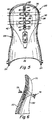
- the highback 20 includes an upright back member 22 and a pair of lateral arms 24 that extend from opposing sides of the back member.
- the lateral arms 24 may be employed to pivotally attach the highback to a gliding board component, such as a snowboard binding, a snowboard boot or a binding interface, along a mounting axis 26 that is transverse to the length of the binding or boot.
- the back member 22 preferably has a contoured configuration that is compatible with the shape of a boot.
- the highback 20 includes a heel cup 28 at the lower end of the back member that is configured to grip and hold the heel portion of the boot.
- the back member 22 transitions from the heel cup 28 to an upper portion 30 of the highback that is configured to extend along the rear portion of the rider's leg to provide heelside support for turning and controlling the board.
- the inner surface of the highback may include resilient pads 32, 34 to increase heel hold, to absorb shock and to facilitate pressure distribution across the boot and leg.
- the highback 20 includes one or more sections in its upper portion that may be configured to provide a desired highback stiffness.
- the upper portion 30 of the highback may include first and second sections 36, 38 that can be flexed relative to the heel cup 28.
- the first section 36 can be flexed relative to the second section 38 which in turn can be flexed relative to the lower portion of the back member 22 above the heel cup 28.
- the degree and direction of flex may be defined by flex zones 40, 42 formed in the back member.
- the flex zones 40, 42 may extend generally parallel to the mounting axis 26 of the highback to allow the sections 36, 38 to flex in a toe-to-heel direction A. It is to be appreciated, however, that the highback may be configured to allow flexibility in any direction as would be appreciated by one of skill in the art. For example, one or more flex zones may be provided transverse to or in multiple directions relative to the mounting axis.
- the overall stiffness of the highback 20 may be established by the number and size of the sections 36, 38.
- the overall stiffness of the highback may be decreased by decreasing the height of each section and increasing the number of sections. It is to be appreciated, therefore, that the number and size of the sections are not limited to the illustrative embodiment shown in the figures.
- the highback 20 may be configured with a particular degree of stiffness by adjusting the flexibility of the highback at selected locations on the back member.
- first and second apertures 46, 48 extend across the upper portion 30 of the back member 22 to form the flex zones 40, 42.
- any suitably configured aperture may be employed to achieve the desired stiffness characteristics for the highback.
- the degree of highback stiffness may be established in any other suitable manner apparent to one of skill in the art.
- the stiffness of the highback 20 may be increased or decreased by varying the thickness or surface texture of the back member 22 at selected locations.
- the stiffness may also be established using various structural members or reliefs, such as ribs or grooves.
- the highback stiffness may also be achieved using materials of varying characteristics at selected locations.
- highback stiffness may be adjusted using one or more control elements 50, 52 that are mountable to the highback.
- the control elements 50, 52 may be disposed in one or more of the apertures 46, 48 to control the relative flexibility of the first and second sections 36, 38 of the highback by acting as compressible wedges between the sections when the rider exerts heelside pressure on the highback.
- control elements 50, 52 are preferably removable so that a rider can readily adjust the overall highback stiffness by interchanging several control elements of varying stiffness.
- the control elements 50, 52 are detachable plugs that may be locked into and removed from the apertures.
- Each plug may include an interlock 54, such as a barb, a tooth, an undercut or the like, that engages a corresponding feature, such as the periphery of the aperture, to retain the plug on the highback during anticipated riding conditions.
- the highback 20 may be provided with two or more plugs of different stiffness characteristics for each aperture to give a rider several options for highback stiffness.
- a rider may adjust the highback stiffness by selectively interchanging one or more of the control elements 50, 52.
- the highback stiffness may be minimized by removing each of the control elements 50, 52 from the highback so that the sections 36, 38 may freely flex.
- highback stiffness may be maximized by attaching rigid control elements 50, 52 to the highback, thereby substantially eliminating highback flexibility for high power transmission and quick board response.
- Intermediate levels of highback stiffness may be achieved by attaching one or more resilient control elements 50, 52 to the highback.
- Various combinations of control elements 50, 52 may also be employed to further adjust the highback stiffness in accordance with the rider's riding preferences as would be apparent to one of skill in the art.
- control elements 50, 52 may be integrally formed on the rear surface of the upper pad 32 so that they protrude through the apertures 46, 48 when the pad is attached to the inner surface of the highback.
- the control elements 50, 52 may be formed of a material having different compressive properties than the pad.
- pads 32 having different stiffness characteristics may be provided to give the rider the option of adjusting the highback stiffness by selectively attaching one of pads to the highback.
- control elements may include one or springs that are interchangeably attached to the highback.
- a spring 56 such as a leaf spring
- the intermediate portion of the spring 56 may be secured between the first and second sections 36, 38 using any suitable fastener 58, such as a screw or the like.
- the opposing ends of the spring 56 may be slidably secured to the highback using any suitable fastener 60, such as a screw, pin or the like, that extends through the spring 56 and corresponding slots 62 in the highback.
- the first end 64 of the spring is slidably secured above the first aperture 46 and the second end 66 of the spring is slidably secured below the second aperture 48.
- the intermediate portion of the spring is fixed to the highback between the first and second apertures so that flexing the first and second sections 36, 38 of the highback causes the first and second ends 64, 66 of the spring to bend about its intermediate portion.
- the degree of highback stiffness may be controlled through the use of particular spring characteristics. For example, a spring with a high spring constant will provide greater highback stiffness than a spring with a low spring constant when subjected to the same applied force.
- the highback 20 is preferably molded from a rigid plastic material, such as polycarbonate, polyolefin, polyurethane, polyethylene and the like, that is capable of providing efficient force transmission from the rider to the board.
- the control elements 50, 52 are preferably molded from a resilient material, such as an elastomer. It is to be appreciated, however, that the highback and control elements may be formed from any suitable material apparent to one of skill in the art. For example, the control elements may be made from various gels, plastics, foams and the like. In another embodiment, the control elements may include interchangeable compression springs or other suitable dampening means apparent to one of skill.
- the stiffness of the highback 20 may be adjusted using a plurality of interchangeable highback uppers, each having a stiffness that differs from the other uppers.
- the uppers may also be provided with shapes having varying curvatures, heights and/or any other feature apparent to one of skill.
- the back member 22 of the highback may detachably support any one of the interchangeable uppers 70 to provide a desired highback stiffness.
- the uppers 70 may be detachably connected to the highback using any suitable fastener apparent to one of skill, such as a screw 72 and nut 74 arrangement.
- the adjustable highback according to the present invention may be employed in any gliding board activity, such as snowboarding, that would benefit from heelside support.
- any gliding board activity such as snowboarding
- the inventive highback is now described below in connection with a snowboard binding.
- the snowboard binding 80 may include a baseplate 82, which is mountable to a snowboard 84, and one or more binding straps, preferably adjustable straps, that are attached to the baseplate for securing a boot (not shown) to the snowboard.
- the highback 20 is pivotally mounted to the sidewalls of the baseplate 82.
- the binding 80 may include an ankle strap 86 that extends across the ankle portion of the boot to hold down the rider's heel and a toe strap 88 that extends across and holds down the front portion of the boot. It is to be understood, however, that the binding 80 may implement other strap configurations.
- a lockdown forward lean adjuster 90 may also be provided to interact with a heel hoop 92 for setting the highback 20 at a preselected forward lean angle relative to the board and to lock down the highback for enhanced toeside response.
- the highback 20 of the present invention is not limited to any particular type of binding.
- the highback may also be implemented with a step-in snowboard binding that includes a locking mechanism that engages corresponding features provided, either directly or indirectly, on a snowboard boot.
- the highback may be mounted to a binding baseplate in a manner similar to the binding described above. Examples of step-in snowboard bindings that may incorporate the flexible highback are described in U.S. patent no. 5,722,680 and U.S. patent application no. 08/780,721.
- the highback 20 of the present invention may be either permanently attached to or removable from a snowboard boot.
- a removable highback provides system flexibility by allowing the boot to be implemented with binding systems that already include a highback mounted to a binding baseplate.
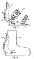
- the highback 20 is movably mounted to the heel region of a boot 100.
- the lateral arms 24 are preferably attached below the ankle portion of the boot for facilitating lateral or side-to-side boot flexibility that allows desirable lateral foot roll.
- the lateral arms 24 may be attached to the boot, preferably at reinforced attachment points, using any suitable fastener 102, such as a screw, rivet or the like, that passes through each lateral arm.
- the flexible highback 20 may be implemented with a detachable binding interface system for interfacing a boot to a binding.
- the interface 110 includes a body 112 and at least one adjustable strap 114 that is arranged to be disposed across the ankle portion of the boot 116, which is shown in phantom.
- the highback 20 is movably mounted to the sidewalls of the interface body 112 using a suitable fastener 115 that passes through the lateral arms 24 of the highback.
- the body 112 of the interface may include one or more mating features 118, as would be apparent to one of skill in the art, that are adapted to engage corresponding engagement members 120 on the binding 122.
- binding interface 110 and binding 122 shown in FIG. 9 is described in greater detail in a U.S. application no. 09/062,131.
Landscapes
- Health & Medical Sciences (AREA)
- General Health & Medical Sciences (AREA)
- Physical Education & Sports Medicine (AREA)
- Chemical & Material Sciences (AREA)
- Engineering & Computer Science (AREA)
- Materials Engineering (AREA)
- Orthopedics, Nursing, And Contraception (AREA)
- Footwear And Its Accessory, Manufacturing Method And Apparatuses (AREA)
- Transition And Organic Metals Composition Catalysts For Addition Polymerization (AREA)
- Adhesives Or Adhesive Processes (AREA)
- Details Or Accessories Of Spraying Plant Or Apparatus (AREA)
Claims (24)
- Snowboardwadenstütze (20) zur Verwendung mit einer mit dem Bein eines Fahrers eine Schnittstelle bildenden und von einem Snowboard stützbaren Komponente, umfassend:einen Wadenstützenkörper mit einem aufrechten Rückteil (22), das zum Stützen eines hinteren Abschnitts des Beins eines Fahrers aufgebaut und angeordnet ist, wobei der Wadenstützenkörper eine kontrollierte Steifheit aufweist, die zwischen einer ersten festen Steifheit und einer von der ersten festen Steifheit verschiedenen, zweiten festen Steifheit einstellbar ist, und der Wadenstützenkörper für den Eingriff mit der Komponente aufgebaut und angeordnet ist; undeine an dem Wadenstützenkörper befestigte Vorwärtsneigungseinstellung (90), die aufgebaut und angeordnet ist, um mit einem Bereich einer Bindung auf einem Snowboard in Eingriff zu treten, so dass die Wadenstütze relativ zum Snowboard auf eine vorgewählte Vorwärtsneigungsstellung festsetzbar ist.
- Wadenstütze nach Anspruch 1, dadurch gekennzeichnet, dass das Rückteil einen unteren Bereich (28) und zumindest einen bewegbar auf dem unteren Bereich getragenen Abschnitt (38) umfasst, und Bewegen des zumindest einen Abschnitts relativ zum unteren Bereich kontrollierbar (52) ist, um die Steifheit des Wadenstützenkörpers einzustellen.
- Wadenstütze nach Anspruch 2, dadurch gekennzeichnet, dass der untere Bereich eine Fersenschale (28) umfasst, und der zumindest eine Abschnitt (38) über der Fersenschale flexibel auf dem unteren Bereich des Rückteils getragen ist.
- Wadenstütze nach Anspruch 3, dadurch gekennzeichnet, dass der Wadenstützenkörper des weiteren ein Paar sich von gegenüberliegenden Seiten des Rückteils erstreckende, seitliche Arme (24) umfasst, die aufgebaut und angeordnet sind, um die Wadenstütze entlang einer Befestigungsachse drehbar an der Komponente zu befestigen, und der zumindest eine Abschnitt entlang einer zur Befestigungsachse im Wesentlichen parallelen Biegezone (42) flexibel getragen ist.
- Wadenstütze nach Anspruch 3, dadurch gekennzeichnet, dass der zumindest eine Abschnitt (38) in einer Richtung Zehen-Ferse flexibel ist.
- Wadenstütze nach Anspruch 3, dadurch gekennzeichnet, dass der zumindest eine Abschnitt (38) relativ zum unteren Bereich des Rückteils entlang einer zumindest teilweise von zumindest einer sich durch das Rückteil erstreckenden Öffnung (48) gebildeten Biegezone (42) flexibel ist.
- Wadenstütze nach Anspruch 6, dadurch gekennzeichnet, dass die zumindest eine Öffnung (48) eine im Wesentlichen ovale, sich quer über das Rückteil erstreckende Form aufweist.
- Wadenstütze nach Anspruch 2, weiterhin zumindest ein Steuerelement (52) umfassend, das zum Begrenzen der Relativbewegung zwischen dem zumindest einen Abschnitt (38) und dem unteren Bereich (28) an dem Wadenstützenkörper befestigbar ist, um die Steifheit des Wadenstützenkörpers in die erste oder die zweite feste Steifheit festzusetzen.
- Wadenstütze nach Anspruch 8, dadurch gekennzeichnet, dass die Steifheit des Wadenstützenkörpers bei an dem Rückteil befestigtem zumindest einen Steuerelement (52) auf die erste feste Steifheit, und bei von dem Rückteil gelöstem zumindest einen Steuerelement (52) auf die zweite feste Steifheit festgesetzt ist.
- Wadenstütze nach Anspruch 8, dadurch gekennzeichnet, dass das zumindest eine Steuerelement (52) ein erstes Steuerelement (52) mit einer ersten Steifheit und ein zweites Steuerelement (52) mit einer von der ersten Steifheit verschiedenen zweiten Steifheit umfasst, das erste Steuerelement zum Festsetzen der Steifheit des Rückteils auf die erste feste Steifheit an dem Rückteil befestigt ist, und das zweite Steuerelement zum Festsetzen der Steifheit des Rückteils auf die zweite feste Steifheit an dem Rückteil befestigt ist.
- Wadenstütze nach Anspruch 8, dadurch gekennzeichnet, dass das zumindest eine Steuerelement einen Stopfen (52) umfasst, der in eine sich durch das Rückteil erstreckende Öffnung (48) einführbar ist.
- Wadenstütze nach Anspruch 11, dadurch gekennzeichnet, dass der Stopfen (52) zwischen dem zumindest einen Abschnitt und dem unteren Bereich komprimierbar ist, um zum Einstellen der Steifheit des Wadenstützenkörpers Relativbewegung zwischen diesen zu begrenzen.
- Wadenstütze nach Anspruch 11, dadurch gekennzeichnet, dass der Stopfen (52) starr ist, um zum Erhöhen der Steifheit des Wadenstützenkörpers Relativbewegung zwischen dem zumindest einen Abschnitt und dem unteren Bereich im Wesentlichen zu eliminieren.
- Wadenstütze nach Anspruch 8, dadurch gekennzeichnet, dass das zumindest eine Steuerelement zumindest eine an dem Rückteil angebrachte Feder (56) umfasst, die eine vorbestimmte Federkonstante aufweist, um die Steifheit des Wadenstützenkörpers auf die erste feste Steifheit oder die zweite feste Steifheit einzustellen.
- Wadenstütze nach Anspruch 14, dadurch gekennzeichnet, dass die Feder eine Blattfeder (56) ist, von der zumindest ein Ende an dem Rückteil gleitend mit diesem verbunden ist.
- Wadenstütze nach Anspruch 2, dadurch gekennzeichnet, dass der zumindest eine Abschnitt einen ersten Abschnitt mit einer ersten Steifheit und einen zweiten Abschnitt mit einer von der ersten Steifheit verschiedenen Steifheit aufweist, wobei die ersten und zweiten Abschnitte austauschbar auf dem Rückteil getragen sind, um die Steifheit zwischen der ersten festen Steifheit und der zweiten festen Steifheit einzustellen.
- Wadenstütze nach Anspruch 1 in Kombination mit der Snowboardkomponente (82), wobei die Wadenstütze an der Snowboardkomponente befestigt ist.
- Wadenstütze nach Anspruch 17, dadurch gekennzeichnet, dass die Snowboardkomponente die Snowboardbindung (80) umfasst, die Binding eine Grundplatte (82) aufweist und die Wadenstütze drehbar an der Grundplatte befestigt ist.
- Wadenstütze nach Anspruch 18, dadurch gekennzeichnet, dass die Snowboardbindung zumindest einen an der Grundplatte befestigten, einstellbaren Riemen (86, 88) umfasst, um einen Snowboardboot zu befestigen.
- Wadenstütze nach Anspruch 18 oder 19, dadurch gekennzeichnet, dass die Snowboardbindung (80) eine Step-in Bindung ist.
- Wadenstütze nach Anspruch 17, dadurch gekennzeichnet, dass die Snowboardkomponente einen Snowboardboot (100) umfasst, und die Wadenstütze drehbar an dem Snowboardboot befestigt ist.
- Wadenstütze nach Anspruch 17, dadurch gekennzeichnet, dass die Snowboardkomponente ein lösbares Bindungsschnittstellenteil (110) umfasst, das aufgebaut und angeordnet ist, um die Schnittstelle von einem Snowboardboot mit der Snowboardbindung zu bilden, und die Wadenstütze drehbar an dem Bindungsschnittstellenteil befestigt ist.
- Wadenstütze nach mindestens einem der vorhergehenden Ansprüche, dadurch gekennzeichnet, dass der Wadenstützenkörper des weiteren ein Paar sich von im Wesentlichen gegenüberliegenden Seiten des Rückteils erstreckende, seitliche Arme (24) umfasst, um die Wadenstütze an der Komponente zu befestigen.
- Wadenstütze nach Anspruch 23, dadurch gekennzeichnet, dass das Rückteil (22) eine sich in einer im Wesentlichen konkaven Form zwischen den gegenüberliegenden Seiten erstreckende Innenfläche aufweist.
Applications Claiming Priority (3)
| Application Number | Priority Date | Filing Date | Title |
|---|---|---|---|
| US169074 | 1998-10-09 | ||
| US09/169,074 US6557865B1 (en) | 1998-10-09 | 1998-10-09 | Highback with adjustable stiffness |
| PCT/US1999/023401 WO2000021621A1 (en) | 1998-10-09 | 1999-10-08 | Highback with adjustable stiffness |
Publications (2)
| Publication Number | Publication Date |
|---|---|
| EP1119397A1 EP1119397A1 (de) | 2001-08-01 |
| EP1119397B1 true EP1119397B1 (de) | 2003-05-07 |
Family
ID=22614172
Family Applications (1)
| Application Number | Title | Priority Date | Filing Date |
|---|---|---|---|
| EP99970335A Expired - Lifetime EP1119397B1 (de) | 1998-10-09 | 1999-10-08 | Snowboardstiefel-unterstützungsvorrichtung mit einstellbarer steifigkeit |
Country Status (7)
| Country | Link |
|---|---|
| US (1) | US6557865B1 (de) |
| EP (1) | EP1119397B1 (de) |
| JP (1) | JP3087523U (de) |
| AT (1) | ATE239533T1 (de) |
| AU (1) | AU1201200A (de) |
| DE (1) | DE69907706T2 (de) |
| WO (1) | WO2000021621A1 (de) |
Families Citing this family (19)
| Publication number | Priority date | Publication date | Assignee | Title |
|---|---|---|---|---|
| AU2634401A (en) * | 2000-01-06 | 2001-07-16 | Burton Corporation, The | Highback formed of multiple materials |
| US6485035B1 (en) | 2000-04-28 | 2002-11-26 | The Burton Corporation | Binding baseplate for a gliding board |
| US6554296B1 (en) | 2000-04-28 | 2003-04-29 | The Burton Corporation | Highback with independent forward lean adjustment |
| US6969075B2 (en) * | 2003-10-21 | 2005-11-29 | The Burton Corporation | Snowboard binding with reduced vertical profile |
| US7134928B1 (en) * | 2005-08-16 | 2006-11-14 | Connelly Skis, Inc. | Binding for water sports boards |
| US8192244B2 (en) * | 2005-08-16 | 2012-06-05 | Connelly Skis, Inc. | Water sports binding assembly |
| US7686321B2 (en) * | 2006-12-01 | 2010-03-30 | The Burton Corporation | Highback with textile-like material for support |
| ITMI20120068A1 (it) * | 2012-01-23 | 2013-07-24 | Martino Fumagalli | Spoiler per attacco da snowboard. |
| US9408435B2 (en) * | 2013-03-14 | 2016-08-09 | Bauer Hockey, Inc. | Skate boot having a tendon guard with a recess |
| US9713758B2 (en) * | 2013-10-16 | 2017-07-25 | Kevin John LEFSRUD | Ski boot frame |
| JP6262542B2 (ja) * | 2014-01-17 | 2018-01-17 | 株式会社カーメイト | スノーボード用ビンディング |
| US20160082343A1 (en) * | 2014-09-22 | 2016-03-24 | Timothy Hughes | Universal snowboard binding |
| US9220970B1 (en) | 2014-11-14 | 2015-12-29 | The Burton Corporation | Snowboard binding and boot |
| US9149711B1 (en) | 2014-11-14 | 2015-10-06 | The Burton Corporation | Snowboard binding and boot |
| EP3218073B1 (de) | 2014-11-14 | 2021-05-19 | The Burton Corporation | Snowboard-bindung |
| USD848137S1 (en) * | 2017-08-28 | 2019-05-14 | ProAdvent LLC | Retention element for ski boot liner |
| US10327500B2 (en) | 2017-08-28 | 2019-06-25 | ProAdvent LLC | Ski boot dynamic support strap |
| JP6997632B2 (ja) * | 2018-01-12 | 2022-01-17 | 株式会社カーメイト | スノーボード用ビンディングのハイバック |
| US20250351918A1 (en) * | 2024-05-16 | 2025-11-20 | Vh Footwear Inc. | Skate boot with stiffening cuff insert |
Family Cites Families (45)
| Publication number | Priority date | Publication date | Assignee | Title |
|---|---|---|---|---|
| US218993A (en) | 1879-08-26 | Improvement in boot and shoe back protectors | ||
| US3419974A (en) | 1966-03-14 | 1969-01-07 | Robert B. Lange | Ski boot |
| US3593435A (en) | 1969-01-06 | 1971-07-20 | Robert B Lange | Plastic ski boot |
| US3645017A (en) | 1969-12-08 | 1972-02-29 | Amf Inc | Ski boot construction |
| US3807060A (en) * | 1973-03-05 | 1974-04-30 | Hanson Ind Inc | Ski boot having multi-directional flexure means and canting means |
| US3945135A (en) * | 1974-03-13 | 1976-03-23 | Hanson Industries Inc. | Ski boot |
| US4078322A (en) | 1976-08-04 | 1978-03-14 | Engineered Sports Products, Inc. | Ski boot |
| US4281468A (en) | 1979-08-16 | 1981-08-04 | Comfort Products, Inc. | Ski boot having a corrugated front portion |
| US4367885A (en) | 1980-04-11 | 1983-01-11 | Alpine Research, Inc. | Ski binding |
| IT8021895V0 (it) | 1980-05-23 | 1980-05-23 | Nordica Spa | Dispositivo per la regolazione della flessibilita' di scarponi da sci e simili. |
| DE3247516A1 (de) | 1982-12-22 | 1984-06-28 | Josef 8069 Jetzendorf Lederer | Schischuh (stichwort: schwenk- und verschiebbare knoechelmanschette) |
| US4669202A (en) | 1984-09-28 | 1987-06-02 | Ottieri Enterprises | Ski boot |
| US4565017A (en) * | 1984-09-28 | 1986-01-21 | Ottieri Enterprises | Ski boot |
| FR2613914B1 (fr) | 1987-04-17 | 1989-06-09 | Salomon Sa | Chaussure de ski alpin |
| CH673935A5 (de) | 1987-11-27 | 1990-04-30 | Raichle Sportschuh Ag | |
| CH677313A5 (en) | 1988-10-19 | 1991-05-15 | Lange Int Sa | Ski boot - has adjustable inner tongue to regulate leg portion of boot to size of wearer's foot |
| IT1243516B (it) | 1990-10-24 | 1994-06-16 | Dolomite Spa | Scarpone da sci con spoiler regolabile |
| FR2669515B1 (fr) | 1990-11-22 | 1993-01-08 | Salomon Sa | Chaussure de ski alpin a chaussage par l'arriere. |
| US5261689A (en) * | 1992-01-28 | 1993-11-16 | Burton Corporation Usa | Snowboard boot binding system |
| CA2084829C (en) | 1992-12-08 | 1999-04-20 | T. Blaine Hoshizaki | Skate boot with moulded plastic overlay |
| US5435080A (en) * | 1992-12-17 | 1995-07-25 | Meiselman; Jamie | Boot for snowboarding and the like |
| CA2089313A1 (en) * | 1993-02-11 | 1994-08-12 | Randy Jespersen | Boot binding system for a snowboard |
| DE4333503C2 (de) | 1993-10-01 | 1995-07-27 | Usp Markeing & Vertriebs Gmbh | Snowboard-Stiefel |
| US5556123A (en) * | 1994-05-12 | 1996-09-17 | Fournier; Louis | Snowboard binding with compensating plate |
| DE4435959C2 (de) | 1994-10-07 | 1997-09-04 | Goodwell Int Ltd | Snowboardstiefel |
| FR2727605A1 (fr) * | 1994-12-02 | 1996-06-07 | Salomon Sa | Chaussure de ski |
| IT1279260B1 (it) | 1995-01-31 | 1997-12-09 | Nordica Spa | Dispositivo di supporto, particolarmente per calzature sportive |
| US5606808A (en) | 1995-03-28 | 1997-03-04 | Gilliard; James F. | Adjustably stiffenable snowboard boot |
| JP2993658B2 (ja) | 1995-06-23 | 1999-12-20 | 株式会社シマノ | スノーボード靴 |
| FR2736806B1 (fr) | 1995-07-17 | 1997-08-14 | Rossignol Sa | Chaussure pour la pratique du surf de neige |
| US5713587A (en) * | 1995-08-11 | 1998-02-03 | Morrow Snowboards, Inc. | Attachment system for snowboards |
| JPH09108398A (ja) | 1995-10-18 | 1997-04-28 | Kureele U:Kk | スノーボーディング用ブーツビンディング装置 |
| DE29700632U1 (de) | 1997-01-17 | 1997-06-05 | Marker Deutschland Gmbh | Snowboard-Bindung |
| DE19602667C1 (de) | 1996-01-25 | 1997-10-16 | F2 Int Gmbh | Snowboardbindung |
| US5727797A (en) * | 1996-02-06 | 1998-03-17 | Preston Binding Company | Snowboard binding assembly with adjustable forward lean backplate |
| US5791678A (en) * | 1996-06-05 | 1998-08-11 | Perlman; Richard I. | Adjustable boot-binding mount for snowboard |
| FR2745691B1 (fr) | 1996-03-06 | 1998-05-29 | Salomon Sa | Batte a tige souple munie d'une ossature de renfort, notamment pour la pratique du surf sur neige |
| WO1997035494A1 (en) | 1996-03-27 | 1997-10-02 | William H. Kaufman Inc. | Downhill snow sport boot assembly |
| GB9620598D0 (en) | 1996-10-03 | 1996-11-20 | Grinnell Mfg Uk Ltd | Thermally responsive frangible bulb |
| FR2755030B1 (fr) * | 1996-10-25 | 1999-01-15 | Salomon Sa | Dispositif de fixation d'une chaussure sur une planche de glisse pour la pratique du surf sur la neige |
| AU5733998A (en) | 1997-01-17 | 1998-08-07 | Switch Manufacturing | Improved snowboard boot ankle support assembly |
| DE29700738U1 (de) | 1997-01-17 | 1997-05-28 | Marker Deutschland Gmbh | Snowboard-Bindung |
| DE29700631U1 (de) | 1997-01-17 | 1997-06-05 | Marker Deutschland Gmbh | Snowboard-Bindung |
| US5832635A (en) | 1997-01-17 | 1998-11-10 | Items International, Inc. | Apparatus for adjusting the forward lean and flexibility of footwear |
| FR2767034B1 (fr) | 1997-08-05 | 1999-09-10 | Salomon Sa | Chaussure de sport a flexibilite determinee |
-
1998
- 1998-10-09 US US09/169,074 patent/US6557865B1/en not_active Expired - Fee Related
-
1999
- 1999-10-08 WO PCT/US1999/023401 patent/WO2000021621A1/en not_active Ceased
- 1999-10-08 DE DE69907706T patent/DE69907706T2/de not_active Expired - Lifetime
- 1999-10-08 JP JP2000600005U patent/JP3087523U/ja not_active Expired - Lifetime
- 1999-10-08 AU AU12012/00A patent/AU1201200A/en not_active Abandoned
- 1999-10-08 AT AT99970335T patent/ATE239533T1/de active
- 1999-10-08 EP EP99970335A patent/EP1119397B1/de not_active Expired - Lifetime
Also Published As
| Publication number | Publication date |
|---|---|
| DE69907706T2 (de) | 2004-03-11 |
| ATE239533T1 (de) | 2003-05-15 |
| JP3087523U (ja) | 2002-08-09 |
| AU1201200A (en) | 2000-05-01 |
| EP1119397A1 (de) | 2001-08-01 |
| WO2000021621A9 (en) | 2000-09-14 |
| WO2000021621A1 (en) | 2000-04-20 |
| DE69907706D1 (de) | 2003-06-12 |
| US6557865B1 (en) | 2003-05-06 |
Similar Documents
| Publication | Publication Date | Title |
|---|---|---|
| US6231057B1 (en) | Highback with an adjustable shape | |
| EP1119397B1 (de) | Snowboardstiefel-unterstützungsvorrichtung mit einstellbarer steifigkeit | |
| US7566062B2 (en) | Highback formed of multiple materials | |
| EP1175250B1 (de) | System für den Gebrauch mit einer Komponente,die mit einem Bein von einem Fahrer interagiert | |
| US6206403B1 (en) | Snowboard strap binding | |
| EP0979045B1 (de) | Aktives unterstützungssystem für einen snowboardstiefel | |
| US6736413B2 (en) | Highback with independent forward lean adjustment | |
| US20100013193A1 (en) | Recreational binding with adjustable suspension interface | |
| US7159892B2 (en) | Snowboard binding with suspension heel loop | |
| US6543793B1 (en) | Highback formed of multiple materials | |
| EP1149611B1 (de) | Grundplatte einer Bindung für Snowboard |
Legal Events
| Date | Code | Title | Description |
|---|---|---|---|
| PUAI | Public reference made under article 153(3) epc to a published international application that has entered the european phase |
Free format text: ORIGINAL CODE: 0009012 |
|
| 17P | Request for examination filed |
Effective date: 20010504 |
|
| AK | Designated contracting states |
Kind code of ref document: A1 Designated state(s): AT BE CH CY DE DK ES FI FR GB GR IE IT LI LU MC NL PT SE |
|
| AX | Request for extension of the european patent |
Free format text: AL;LT;LV;MK;RO;SI |
|
| 17Q | First examination report despatched |
Effective date: 20010820 |
|
| GRAG | Despatch of communication of intention to grant |
Free format text: ORIGINAL CODE: EPIDOS AGRA |
|
| GRAG | Despatch of communication of intention to grant |
Free format text: ORIGINAL CODE: EPIDOS AGRA |
|
| GRAG | Despatch of communication of intention to grant |
Free format text: ORIGINAL CODE: EPIDOS AGRA |
|
| GRAH | Despatch of communication of intention to grant a patent |
Free format text: ORIGINAL CODE: EPIDOS IGRA |
|
| GRAH | Despatch of communication of intention to grant a patent |
Free format text: ORIGINAL CODE: EPIDOS IGRA |
|
| GRAA | (expected) grant |
Free format text: ORIGINAL CODE: 0009210 |
|
| AK | Designated contracting states |
Designated state(s): AT CH DE FR IT LI |
|
| REG | Reference to a national code |
Ref country code: CH Ref legal event code: EP |
|
| REG | Reference to a national code |
Ref country code: CH Ref legal event code: NV Representative=s name: KATZAROV S.A. |
|
| REG | Reference to a national code |
Ref country code: IE Ref legal event code: FG4D |
|
| REF | Corresponds to: |
Ref document number: 69907706 Country of ref document: DE Date of ref document: 20030612 Kind code of ref document: P |
|
| LTIE | Lt: invalidation of european patent or patent extension |
Effective date: 20030507 |
|
| ET | Fr: translation filed | ||
| PLBE | No opposition filed within time limit |
Free format text: ORIGINAL CODE: 0009261 |
|
| STAA | Information on the status of an ep patent application or granted ep patent |
Free format text: STATUS: NO OPPOSITION FILED WITHIN TIME LIMIT |
|
| 26N | No opposition filed |
Effective date: 20040210 |
|
| PGFP | Annual fee paid to national office [announced via postgrant information from national office to epo] |
Ref country code: CH Payment date: 20131021 Year of fee payment: 15 Ref country code: DE Payment date: 20131021 Year of fee payment: 15 Ref country code: FR Payment date: 20131022 Year of fee payment: 15 Ref country code: AT Payment date: 20131011 Year of fee payment: 15 |
|
| PGFP | Annual fee paid to national office [announced via postgrant information from national office to epo] |
Ref country code: IT Payment date: 20131024 Year of fee payment: 15 |
|
| REG | Reference to a national code |
Ref country code: DE Ref legal event code: R119 Ref document number: 69907706 Country of ref document: DE |
|
| REG | Reference to a national code |
Ref country code: CH Ref legal event code: PL |
|
| REG | Reference to a national code |
Ref country code: AT Ref legal event code: MM01 Ref document number: 239533 Country of ref document: AT Kind code of ref document: T Effective date: 20141008 |
|
| PG25 | Lapsed in a contracting state [announced via postgrant information from national office to epo] |
Ref country code: LI Free format text: LAPSE BECAUSE OF NON-PAYMENT OF DUE FEES Effective date: 20141031 Ref country code: DE Free format text: LAPSE BECAUSE OF NON-PAYMENT OF DUE FEES Effective date: 20150501 Ref country code: CH Free format text: LAPSE BECAUSE OF NON-PAYMENT OF DUE FEES Effective date: 20141031 |
|
| REG | Reference to a national code |
Ref country code: FR Ref legal event code: ST Effective date: 20150630 |
|
| PG25 | Lapsed in a contracting state [announced via postgrant information from national office to epo] |
Ref country code: FR Free format text: LAPSE BECAUSE OF NON-PAYMENT OF DUE FEES Effective date: 20141031 Ref country code: AT Free format text: LAPSE BECAUSE OF NON-PAYMENT OF DUE FEES Effective date: 20141008 Ref country code: IT Free format text: LAPSE BECAUSE OF NON-PAYMENT OF DUE FEES Effective date: 20141008 |