EP1120164B1 - Flüssigkeitsströmungskontrolle in gebogenen Kapillarkanälen - Google Patents
Flüssigkeitsströmungskontrolle in gebogenen Kapillarkanälen Download PDFInfo
- Publication number
- EP1120164B1 EP1120164B1 EP01101403A EP01101403A EP1120164B1 EP 1120164 B1 EP1120164 B1 EP 1120164B1 EP 01101403 A EP01101403 A EP 01101403A EP 01101403 A EP01101403 A EP 01101403A EP 1120164 B1 EP1120164 B1 EP 1120164B1
- Authority
- EP
- European Patent Office
- Prior art keywords
- capillary
- microstructures
- pathway
- wall
- group
- Prior art date
- Legal status (The legal status is an assumption and is not a legal conclusion. Google has not performed a legal analysis and makes no representation as to the accuracy of the status listed.)
- Expired - Lifetime
Links
Images




Classifications
-
- B—PERFORMING OPERATIONS; TRANSPORTING
- B01—PHYSICAL OR CHEMICAL PROCESSES OR APPARATUS IN GENERAL
- B01L—CHEMICAL OR PHYSICAL LABORATORY APPARATUS FOR GENERAL USE
- B01L3/00—Containers or dishes for laboratory use, e.g. laboratory glassware; Droppers
- B01L3/50—Containers for the purpose of retaining a material to be analysed, e.g. test tubes
- B01L3/502—Containers for the purpose of retaining a material to be analysed, e.g. test tubes with fluid transport, e.g. in multi-compartment structures
- B01L3/5027—Containers for the purpose of retaining a material to be analysed, e.g. test tubes with fluid transport, e.g. in multi-compartment structures by integrated microfluidic structures, i.e. dimensions of channels and chambers are such that surface tension forces are important, e.g. lab-on-a-chip
- B01L3/502746—Containers for the purpose of retaining a material to be analysed, e.g. test tubes with fluid transport, e.g. in multi-compartment structures by integrated microfluidic structures, i.e. dimensions of channels and chambers are such that surface tension forces are important, e.g. lab-on-a-chip characterised by the means for controlling flow resistance, e.g. flow controllers, baffles or throttle valves
-
- B—PERFORMING OPERATIONS; TRANSPORTING
- B01—PHYSICAL OR CHEMICAL PROCESSES OR APPARATUS IN GENERAL
- B01L—CHEMICAL OR PHYSICAL LABORATORY APPARATUS FOR GENERAL USE
- B01L2300/00—Additional constructional details
- B01L2300/08—Geometry, shape and general structure
- B01L2300/0861—Configuration of multiple channels and/or chambers in a single devices
-
- B—PERFORMING OPERATIONS; TRANSPORTING
- B01—PHYSICAL OR CHEMICAL PROCESSES OR APPARATUS IN GENERAL
- B01L—CHEMICAL OR PHYSICAL LABORATORY APPARATUS FOR GENERAL USE
- B01L2300/00—Additional constructional details
- B01L2300/08—Geometry, shape and general structure
- B01L2300/0887—Laminated structure
-
- B—PERFORMING OPERATIONS; TRANSPORTING
- B01—PHYSICAL OR CHEMICAL PROCESSES OR APPARATUS IN GENERAL
- B01L—CHEMICAL OR PHYSICAL LABORATORY APPARATUS FOR GENERAL USE
- B01L2400/00—Moving or stopping fluids
- B01L2400/04—Moving fluids with specific forces or mechanical means
- B01L2400/0403—Moving fluids with specific forces or mechanical means specific forces
- B01L2400/0406—Moving fluids with specific forces or mechanical means specific forces capillary forces
-
- B—PERFORMING OPERATIONS; TRANSPORTING
- B01—PHYSICAL OR CHEMICAL PROCESSES OR APPARATUS IN GENERAL
- B01L—CHEMICAL OR PHYSICAL LABORATORY APPARATUS FOR GENERAL USE
- B01L2400/00—Moving or stopping fluids
- B01L2400/08—Regulating or influencing the flow resistance
- B01L2400/084—Passive control of flow resistance
- B01L2400/086—Passive control of flow resistance using baffles or other fixed flow obstructions
Definitions
- the present invention is directed to physical structures and methods for controlling the flow of small volumes of liquids such as blood through capillary devices.
- the present invention is particularly directed to such structures that include curved capillary flow paths and microstructures which can be positioned in the flow path to promote uniform capillary pull around the curve.
- the present invention also concerns capillary channels that connect to such curved capillary flow paths.
- Capillary structures are often employed when handling such small volumes of blood or other fluids particularly in combination with electrochemical sensors.
- the capillary structures can be included in analyte sensing apparatus configured in the form of a disposable test strip adapted to cooperate with electrical circuitry of a testing instrument.
- the test strip generally includes a first defined area to which a biological fluid is to be applied. At least one capillary pathway leads from the first area to one or more second areas containing sensing apparatus such as electrodes or optical windows.
- Reagent chemical compositions can also be included in one or more of the capillary pathways or second areas containing the sensing electrodes.
- the testing instrument is generally programmed to apply a preselected potential to the sensing electrodes at a predetermined time following application of the biological fluid to the first defined area. The current flowing between given pairs of the sensing electrodes through the biological fluid is then measured to provide an indication of the presence and/or concentration of one or more target analytes in the biological fluid. Following the testing, the test strip can be removed from the testing instrument and suitably disposed.
- Some electrochemical sensors of this general type include structures intended to promote the transport of plasma, while substantially excluding or inhibiting the passage of erythrocytes to the area or areas containing the sensing electrodes.
- Example devices are disclosed in U.S. Patent 5,658,444 and in European Patent Application 88303760.8.
- Other sensors include grooves and other structures designed to direct fluid flow along prescribed paths such as in U.S. Patents 4,233,029 and 4,618,476.
- the test strips including such capillary pathways are generally constructed in a layered geometry as shown, for example, in U.S. Patent 5,798,031.
- a fluid transport structure of the present invention generally includes a capillary pathway having at least one curved portion according to claim 1.
- the pathway curved portion can be viewed as comprising a base, an inner wall defined by a first radius and an outer wall situated generally parallel to the inner wall and defined by a second radius greater than the first radius.
- the inner wall and outer wall are fixed to the base and define the lateral boundaries of the capillary pathway.
- a lid extends at least from the inner wall to the outer wall to cover the capillary pathway.
- the capillary pathway includes apparatus facilitating the transport of a liquid longitudinally through the pathway.
- the apparatus generally comprises at least one group of microstructures fixed to the base that occupy entirely the capillary pathway between the inner and outer walls.
- microstructures within each group are generally spaced from each other on a nearest neighbor basis by a first distance that is less than the distance necessary to achieve capillary flow of liquid.
- Each group of microstructures is confined to a discrete arcuate segment of the curved portion of the capillary pathway, and is spaced from any adjacent group by a distance greater than the first distance.
- the microstructures can comprise a variety of shapes.
- a preferred shape for the microstructures is one of partitions having longitudinal dimensions about equal to the discrete arcuate segment occupied by the group. Each partition is preferably arcuate, but can also be linear, or even zig-zag.
- Another preferred shape for the microstructures is posts arranged in a triangular close pack configuration. Each posts can have a variety of shapes in cross-section, such as circular, diamond, square, 1 ⁇ 2 moon, triangle, etc. At least some of the posts adjacent to either of the walls can be joined to the walls by radial extensions.
- the microstructures located closer to the inner wall of the curved portion of the capillary pathway are smaller than the microstructures located closer to the outer wall.
- the microstructures within each group are preferably centered on centers which are equally spaced from each other.
- the fluid transport structure of the present invention can also include at least one capillary channel coupled to the capillary pathway curved portion generally between two adjacent groups of the microstructures.
- Fluid flow into the capillary channels is generally a function of the lateral dimensions of the capillary channels and can be controlled at least in part by the spacing of the microstructures in the capillary pathway adjacent to the capillary channels.
- the walls defining the lateral boundaries of the capillary channels are much closer to each other than are the inner and outer walls of the capillary pathway. To achieve differences in fill times, the walls defining the lateral boundaries of any two capillary channels are generally spaced apart by different distances.
- a biological fluid handling structure can be molded as two or more pieces of a thermoplastic resin such as nylon, styrene-acrylic copolymer, polystyrene, or polycarbonate using known micro-injection molding processes.
- the mold for making the obstructions in the capillary pathway can be constructed by deep reactive ion etching processes typically employed in the manufacture of molds for pre-recorded compact disks and digital video disks.
- a suitable dry reagent can be situated at desired locations in the structure, if desired.
- the pieces of the structure are then assembled so that the capillary pathway is enclosed within the structure, yet can be accessed at an inlet port designed to receive a sample of a biological fluid.
- the apparatus is suitable for use with many types of fluid samples. For example body fluids such as whole blood, blood serum, urine, and cerebrospinal fluid can be applied to the apparatus. Also food products, fermentation products and environmental substances, which potentially contain environmental contaminants, can be applied to the apparatus.
- the resulting structure can be viewed as an apparatus including a capillary pathway defined by a base, an inner wall and an outer wall situated generally parallel to the inner wall, the inner wall and outer wall being fixed to the base and defining lateral boundaries of the capillary pathway, and a lid extending at least from the inner wall to the outer wall covering the capillary pathway.
- the capillary pathway includes one or more groups of microstructures fixed to the base within discrete segments of the pathway for facilitating the transport of a liquid longitudinally through the pathway. At least two capillary channels are coupled between two adjacent groups of microstructures to either the inner and outer wall of the capillary pathway.
- Each capillary channel includes a pair of side walls defining lateral boundaries of each capillary channel, each pair of side walls of all capillary channels being selectively spaced from each other yet closer to each other than are the inner and outer walls of the capillary pathway, the pair of side walls of one of the capillary channels being spaced apart by a different distance than one other capillary channel.
- the grouped microstructures are spaced from each other within each group on a nearest neighbor basis by less than a first distance that is less than that necessary to achieve capillary flow of liquid with each group being confined to a discrete arcuate segment of a curved portion of the capillary pathway.
- Each group of microstructures are spaced from any adjacent group by an inter-group space greater than the width of any of the capillary channels connected to the capillary pathway.
- the microstructures are centered on centers which are equally spaced from each other, and microstructures that are located closer to the inner wall of any curve in the capillary pathway are generally smaller than the microstructures located closer to the outer wall.
- FIGs 1-4 A sensor apparatus 10 for testing for biologically significant analytes of an applied biological fluid is shown in FIGs 1-4, the apparatus being illustrative of the present invention.
- the sensor apparatus 10 is in the form of an easily disposable test strip 12 that includes a fluid inlet port 14 for receiving a biological fluid to be tested.
- a pattern of capillary pathways 16 and smaller channels 18 lead to a variety of testing sites 20.
- Each of the testing sites 20 includes an optical or electrochemical sensor illustrated as pair of electrodes 22 which are shown leading from a testing site 20 to an edge of the test strip 12 to be connected to a suitable testing apparatus, not shown.
- the capillary pathways 16 include curved portions 24, 26 and 28. The curved portions are of particular interest to the present invention as are the junctions between the curved portions and the smaller capillary channels 18.
- FIG. 2 A perspective view of a portion of the sensor apparatus 10 is shown in FIG. 2.
- the apparatus 10 is shown to include a capillary pathway 16 having at least one curved portion such as portion 24.
- the pathway curved portion 24 is defined by a base 30 shown to be a depressed region in a substrate 31, a curved inner wall 32 and a curved outer wall 34.
- the walls 32 and 34 are generally concentric about, and spaced from, a common center 33 situated at a point interior of the walls 32 and 34.
- the inner wall 32 and outer wall 34 are fixed to and integral with the base 30 and define the lateral boundaries of the capillary pathway 16.
- a lid 36 which can be transparent at least over the testing sites 20, extends at least from the inner wall 32 to the outer wall 34, and preferably over the entire substrate 31 to cover the capillary pathway 16. Air vents 35 can be included in the lid 36 or the substrate 31 adjacent the testing sites 20 to permit air to escape from the apparatus as a specimen fluid is pulled into the apparatus by the capillary action.
- a surface of the lid 36 confronting the substrate 31 carries the electrodes 22 from the various testing sites 20 to an exposed edge of the lid 36 so that the terminal ends of the electrodes 22 project from the edge of the substrate 31.
- the terminal ends of the electrodes are intended to connect to apparatus such as preprogrammed sensor reading apparatus designed to apply a predetermined potential to the electrodes after a predetermined time interval following delivery of a liquid sample to the inlet port 14. Current flow through the sample can be measured to provide an indication of the presence and/or concentration of a target analyte.
- a preferred embodiment for the electrodes 22 is illustrated in FIG. 5 comprising a central electrode 37, which is shown to be square but could also be round or another convenient shape, and a peripheral electrode 39 substantially surrounding the central electrode 37.
- the electrodes 22 can be formed by standard lithography processes commonly used in the semi-conductor industry.
- the transparent character of the lid 36 at least over the testing sites 20 permits an optical sensor, not shown, to observe the sample interaction with a reagent to provide an indication of the presence and/or concentration of a target analyte.
- the capillary pathway 16 includes apparatus facilitating the transport of a liquid longitudinally through the pathway.
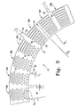
- the apparatus is shown in FIGs 2-4 and generally comprises groups 38a-38g of microstructures 40 fixed to the base 30 that generally occupy the entire width of the capillary pathway between the inner and outer walls 32 and 34, respectively defined by radii R 1 and R 2 .
- the microstructures 40 within each group 38 are shown to be of two general types, posts 42 and fences 44.
- the microstructures 40 are generally spaced from each other, on a nearest neighbor basis, by a first distance that is less than the distance necessary to achieve capillary flow of liquid between the microstructures.
- Each group 38 of microstructures 40 is confined to a discrete arcuate segment ⁇ of the curved portion of the capillary pathway, and is spaced from any adjacent group by an inter-group space of distance ⁇ .
- the arcuate segment ⁇ is a minor portion of the arc involved in the curved portion, of about 5° to 15°. With shorter radius curved portions, the arcuate segment ⁇ will generally occupy a larger portion of the arc.
- the inter-group space distance ⁇ is generally smaller than ⁇ , yet larger than the spacing between adjacent microstructures 40 within any single group 38.
- the microstructures 40 can comprise a variety of shapes.
- a preferred shape for the microstructures is as arcuate partitions 44 having longitudinal dimensions about equal to the discrete arcuate segment ⁇ occupied by the group 38 containing the partitions 44 as shown in groups 38d through 38g.
- Another preferred shape for the microstructures 40 is as round posts 42 arranged in a triangular close pack configuration as shown in groups 38a through 38d. At least some of the posts 43 adjacent to either of the walls 32 or 34 can be joined to the walls as shown in FIG 4.
- the microstructures 40 located closer to the inner wall 32 of the curved portion of the capillary pathway 16 are smaller than the microstructures located closer to the outer wall 34.
- the microstructures 40 within each group are preferably centered on centers which are equally spaced from each other by a center separation distance ⁇ .
- the fluid transport structure of the present invention can also include capillary channels 50 coupled to the capillary pathway 16 generally between two adjacent groups 38 of the microstructures 40. Fluid flow into the capillary channels 50 is generally a function of the lateral dimensions ⁇ of the capillary channels.
- the fluid flow can be controlled at least in part by the spacing of the microstructures 40 in the capillary pathway 16 adjacent to the capillary channels 50.
- the walls 52 and 54 defining the lateral boundaries of the capillary channels 50 are much closer to each other than are the inner and outer walls 32 and 34 of the capillary pathway 16.
- the walls 52 and 54 defining the lateral boundaries of any two capillary channels are generally spaced apart by different distances ⁇ 1 , ⁇ 2 , and ⁇ 3 .
- a biological fluid handling structure according to the present invention can be molded as one or two or more pieces of a thermoplastic resin.
- Suitable resins include thermoplastics such acrylonitrile butadine styrene (ABS), acetal, acrylic, polycarbonate (PC), polyester, polyethylene, fluroplastic, polimide, nylon, polyphenylene oxide, polypropylene (PP) styrene-acrylic copolymer, polystyrene, polysulphone, polyvinyl chloride, poly(methacrylate), poly(methyl methacrylate), or polycarbonate, or mixtures or copolymers thereof.
- the substrate 31 includes a polycarbonate, such as those used in making compact discs.
- the substrate 31 does not contain any reinforcing material, and only contains a thermoplastic material such as polycarbonate.
- the lid 36 and substrate 31 can be formed using known micro-injection molding processes.
- the mold for making the obstructions in the capillary pathway can be constructed by deep reactive ion etching processes typically employed in the manufacture of molds for pre-recorded compact disks and digital video disks.
- a suitable dry reagent can be situated at desired locations in the structure, if desired.
- the pieces of the structure are then assembled so that the capillary pathway 16 is enclosed within the structure, yet can be accessed at an inlet port 14 designed to receive a sample of a fluid having a volume of 100 ⁇ l or less, more typically having a volume of about 5-10 ⁇ l, and preferably having a volume of about 2-3 ⁇ l.
Landscapes
- Chemical & Material Sciences (AREA)
- Health & Medical Sciences (AREA)
- Dispersion Chemistry (AREA)
- Analytical Chemistry (AREA)
- General Health & Medical Sciences (AREA)
- Hematology (AREA)
- Clinical Laboratory Science (AREA)
- Chemical Kinetics & Catalysis (AREA)
- Automatic Analysis And Handling Materials Therefor (AREA)
- Physical Or Chemical Processes And Apparatus (AREA)
- Feeding, Discharge, Calcimining, Fusing, And Gas-Generation Devices (AREA)
- Temperature-Responsive Valves (AREA)
Claims (12)
- Kapillare Bahn mit mindestens einem gekrümmten Abschnitt, wobei der gekrümmte Abschnitt der Bahn eine Basis, eine Innenwand, die durch einen ersten Radius von einem Mittelpunkt bestimmt ist, und eine Außenwand umfasst, die im Allgemeinen konzentrisch um den Mittelpunkt verläuft und durch einen zweiten Radius bestimmt ist, der größer als der erste Radius ist, wobei die Innen- und die Außenwand an der Basis befestigt sind und seitliche Begrenzungen der kapillaren Bahn bestimmen, sowie einen Deckel, der sich mindestens von der Innenwand zur Außenwand erstreckt und der die kapillare Bahn bedeckt, wobei die kapillare Bahn eine Vorrichtung umfasst, die den Transport einer Flüssigkeit längs durch die Bahn erleichtert und die Folgendes umfasst:Gruppen von Mikrostrukturen, die zwischen der Innen- und der Außenwand an der Basis in der kapillaren Bahn befestigt sind, wobei die Mikrostrukturen jeder Gruppe voneinander auf der Basis eines nächsten Nachbarn durch weniger als einen ersten Abstand beabstandet sind, der geringer ist als der, der zum Erzielen eines Kapillarflusses von Flüssigkeit erforderlich ist, wobei jede Gruppe auf ein einzelnes Bogensegment des mindestens einen gekrümmten Abschnitts der kapillaren Bahn eingegrenzt ist, wobei jede Gruppe von einer benachbarten Gruppe durch einen zweiten Abstand beabstandet ist, der größer als der erste Abstand ist und ein Längssegment der kapillaren Bahn bestimmt.
- Vorrichtung nach Anspruch 1, wobei mindestens einige der Mikrostrukturen innerhalb mindestens einer der Gruppen bogenförmige Trennwände mit Längsabmessungen aufweisen, die etwa gleich dem einzelnen Bogensegment sind, das von der mindestens einen Gruppe eingenommen wird.
- Vorrichtung nach Anspruch 1, wobei mindestens einige der Mikrostrukturen innerhalb mindestens einer der Gruppen Stäbe umfassen.
- Vorrichtung nach Anspruch 3, wobei die Stäbe in einer einheitlich beabstandeten, dreieckigen, eng zusammenstehenden Anordnung angeordnet sind.
- Vorrichtung nach Anspruch 4, wobei mindestens einige der Stäbe, die zu einer der Wände benachbart sind, mit den Wänden verbunden sind.
- Vorrichtung nach Anspruch 1, wobei die Mikrostrukturen, die zu der Innen- und der Außenwand benachbart sind, von den benachbarten Wänden durch einen Abstand beabstandet sind, der geringer ist als der erste Abstand.
- Vorrichtung nach Anspruch 1, wobei die Mikrostrukturen, die sich näher zur Innenwand befinden, kleiner sind als die Mikrostrukturen, die sich näher zur Außenwand befinden.
- Vorrichtung nach Anspruch 7, wobei die Mikrostrukturen auf Mittelpunkten zentriert sind, die einheitlich voneinander beabstandet sind.
- Vorrichtung nach Anspruch 7, die ferner mindestens einen Kapillarkanal umfasst, der zwischen zwei benachbarten Gruppen der Mikrostrukturen an den gekrümmten Abschnitt der kapillaren Bahn gekoppelt ist.
- Vorrichtung nach Anspruch 9, wobei Wände, die seitliche Begrenzungen des mindestens einen Kapillarkanals bestimmen, einander näher sind als die Innen- und die Außenwand der kapillaren Bahn.
- Vorrichtung nach Anspruch 10, wobei es mindesten zwei Kapillarkanäle gibt, die an die kapillare Bahn gekoppelt sind.
- Vorrichtung nach Anspruch 11, wobei die Wände, die die seitlichen Begrenzungen der mindestens zwei Kapillarkanäle bestimmen, durch unterschiedliche Abstände voneinander beabstandet sind.
Applications Claiming Priority (2)
| Application Number | Priority Date | Filing Date | Title |
|---|---|---|---|
| US493883 | 2000-01-28 | ||
| US09/493,883 US6451264B1 (en) | 2000-01-28 | 2000-01-28 | Fluid flow control in curved capillary channels |
Publications (3)
| Publication Number | Publication Date |
|---|---|
| EP1120164A2 EP1120164A2 (de) | 2001-08-01 |
| EP1120164A3 EP1120164A3 (de) | 2002-02-06 |
| EP1120164B1 true EP1120164B1 (de) | 2007-03-28 |
Family
ID=23962091
Family Applications (1)
| Application Number | Title | Priority Date | Filing Date |
|---|---|---|---|
| EP01101403A Expired - Lifetime EP1120164B1 (de) | 2000-01-28 | 2001-01-23 | Flüssigkeitsströmungskontrolle in gebogenen Kapillarkanälen |
Country Status (5)
| Country | Link |
|---|---|
| US (1) | US6451264B1 (de) |
| EP (1) | EP1120164B1 (de) |
| AT (1) | ATE357974T1 (de) |
| CA (1) | CA2331588A1 (de) |
| DE (1) | DE60127472T2 (de) |
Cited By (2)
| Publication number | Priority date | Publication date | Assignee | Title |
|---|---|---|---|---|
| US8268262B2 (en) | 2001-08-28 | 2012-09-18 | Gyros Patent Ab | Retaining microfluidic microcavity and other microfluidic structures |
| US8722423B2 (en) | 2004-03-24 | 2014-05-13 | Johnson & Johnson Ab | Assay method utilizing capillary transport on non-porous substrates |
Families Citing this family (83)
| Publication number | Priority date | Publication date | Assignee | Title |
|---|---|---|---|---|
| DE19815882A1 (de) * | 1998-04-08 | 1999-10-14 | Fuhr Guenther | Verfahren und Vorrichtung zur Manipulierung von Mikropartikeln in Fluidströmungen |
| EP1311346A4 (de) * | 2000-06-19 | 2003-07-30 | Caliper Techn Corp | Verfahren und vorrichtungen zur erhöhung der gebundenen substratausbeuten und temperaturregelung |
| US6759009B2 (en) * | 2001-05-04 | 2004-07-06 | Portascience Incorporated | Method and device for clotting time assay |
| EP2281633A1 (de) * | 2001-08-28 | 2011-02-09 | Gyros Patent Ab | Mikrokammern und mikrofluidische Strukturen zur Handhabung kleiner Flüssigkeitsmengen |
| US6755949B1 (en) | 2001-10-09 | 2004-06-29 | Roche Diagnostics Corporation | Biosensor |
| EP1444338A4 (de) * | 2001-11-15 | 2007-07-04 | Arryx Inc | Probenchip |
| DE20202056U1 (de) | 2002-02-12 | 2002-07-04 | Dr. Müller Gerätebau GmbH, 01705 Freital | Mikrochip zur Bestimmung der Stoffkonzentration von Flüssigkeitsbestandteilen |
| US7883670B2 (en) * | 2002-02-14 | 2011-02-08 | Battelle Memorial Institute | Methods of making devices by stacking sheets and processes of conducting unit operations using such devices |
| SE0201738D0 (sv) * | 2002-06-07 | 2002-06-07 | Aamic Ab | Micro-fluid structures |
| US7005301B2 (en) * | 2002-06-10 | 2006-02-28 | Sandia National Laboratories | Piecewise uniform conduction-like flow channels and method therefor |
| US7699767B2 (en) | 2002-07-31 | 2010-04-20 | Arryx, Inc. | Multiple laminar flow-based particle and cellular separation with laser steering |
| US7118676B2 (en) * | 2003-09-04 | 2006-10-10 | Arryx, Inc. | Multiple laminar flow-based particle and cellular separation with laser steering |
| US11243494B2 (en) | 2002-07-31 | 2022-02-08 | Abs Global, Inc. | Multiple laminar flow-based particle and cellular separation with laser steering |
| EP3229240A1 (de) | 2002-07-31 | 2017-10-11 | Premium Genetics (UK) Limited | System und verfahren zum sortieren von materialien mit holografischer lasersteuerung |
| US20040166551A1 (en) * | 2003-02-24 | 2004-08-26 | John Moulds | Detection of agglutination of assays |
| US20040191127A1 (en) * | 2003-03-31 | 2004-09-30 | Avinoam Kornblit | Method and apparatus for controlling the movement of a liquid on a nanostructured or microstructured surface |
| DE10326607A1 (de) * | 2003-06-13 | 2005-01-05 | Steag Microparts Gmbh | Vorrichtung zum Handhaben von Flüssigkeiten |
| US20040265172A1 (en) * | 2003-06-27 | 2004-12-30 | Pugia Michael J. | Method and apparatus for entry and storage of specimens into a microfluidic device |
| CA2544353A1 (en) | 2003-10-29 | 2005-05-12 | Mec Dynamics Corp. | Micro mechanical methods and systems for performing assays |
| DE10352535A1 (de) * | 2003-11-07 | 2005-06-16 | Steag Microparts Gmbh | Mikrostrukturierte Trennvorrichtung und Verfahren zum Abtrennen von flüssigen Bestandteilen aus einer Partikel enthaltenden Flüssigkeit |
| GB0329220D0 (en) * | 2003-12-17 | 2004-01-21 | Inverness Medical Switzerland | System |
| US20090162940A1 (en) * | 2004-05-28 | 2009-06-25 | Wardlaw Stephen C | Specimen Analysis Tube |
| SE527036C2 (sv) * | 2004-06-02 | 2005-12-13 | Aamic Ab | Analysanordning med reglerat flöde och motsvarande förfarande |
| DE102004033317A1 (de) * | 2004-07-09 | 2006-02-09 | Roche Diagnostics Gmbh | Analytisches Testelement |
| KR100705361B1 (ko) | 2004-08-21 | 2007-04-10 | 주식회사 엘지생명과학 | 모세관 유동 제어 모듈 및 이를 구비한 랩온어칩 |
| US7608446B2 (en) | 2004-09-30 | 2009-10-27 | Alcatel-Lucent Usa Inc. | Nanostructured surface for microparticle analysis and manipulation |
| WO2006061026A2 (en) * | 2004-12-09 | 2006-06-15 | Inverness Medical Switzerland Gmbh | A micro fluidic device and methods for producing a micro fluidic device |
| EP1843849A2 (de) * | 2005-01-12 | 2007-10-17 | Inverness Medical Switzerland GmbH | Verfahren zur herstellung einer mikrofluidischen vorrichtung und mikrofluidische vorrichtungen |
| US7678495B2 (en) | 2005-01-31 | 2010-03-16 | Alcatel-Lucent Usa Inc. | Graphitic nanostructured battery |
| JP2008532005A (ja) * | 2005-02-25 | 2008-08-14 | インバーネス・メデイカル・スウイツツアーランド・ゲゼルシヤフト・ミツト・ベシユレンクテル・ハフツング | 流体ゲート装置 |
| SE528233C2 (sv) * | 2005-06-20 | 2006-09-26 | Aamic Ab | Metod och medel för att åstadkomma vätsketransport |
| US20080226502A1 (en) * | 2005-07-07 | 2008-09-18 | Jacques Jonsmann | Microfluidic Methods and Support Instruments |
| US7666665B2 (en) | 2005-08-31 | 2010-02-23 | Alcatel-Lucent Usa Inc. | Low adsorption surface |
| US7412938B2 (en) | 2005-09-15 | 2008-08-19 | Lucent Technologies Inc. | Structured surfaces with controlled flow resistance |
| US8721161B2 (en) | 2005-09-15 | 2014-05-13 | Alcatel Lucent | Fluid oscillations on structured surfaces |
| US8734003B2 (en) | 2005-09-15 | 2014-05-27 | Alcatel Lucent | Micro-chemical mixing |
| US8287808B2 (en) | 2005-09-15 | 2012-10-16 | Alcatel Lucent | Surface for reversible wetting-dewetting |
| WO2007066518A1 (ja) * | 2005-12-08 | 2007-06-14 | Nec Corporation | 接液構造、液体の移動制御構造、および液体の移動制御方法 |
| ATE432125T1 (de) | 2006-02-09 | 2009-06-15 | Hoffmann La Roche | Auf 2d-substraten basierende 3d-strukturen |
| US20070263477A1 (en) * | 2006-05-11 | 2007-11-15 | The Texas A&M University System | Method for mixing fluids in microfluidic channels |
| KR100726339B1 (ko) | 2006-06-15 | 2007-06-11 | 한국과학기술원 | 미세입자 정렬분리용 미세유체칩 및 이를 이용한 미세입자분리방법 |
| JP5137551B2 (ja) * | 2006-12-28 | 2013-02-06 | キヤノン株式会社 | 生化学反応カセット |
| EP1939136A3 (de) * | 2006-12-29 | 2013-03-27 | Corning Incorporated | Druckfeste mikrofluidische Vorrichtungen mit hohem Durchsatz |
| WO2008083687A1 (en) * | 2007-01-10 | 2008-07-17 | Scandinavian Micro Biodevices Aps | A microfluidic device and a microfluidic system and a method of performing a test |
| SE533514C2 (sv) * | 2008-06-16 | 2010-10-12 | Aamic Ab | Analysanordning och förfarande |
| JP5242503B2 (ja) * | 2008-06-16 | 2013-07-24 | オーミック・アーベー | アッセイ装置および方法 |
| US8974749B2 (en) | 2008-06-16 | 2015-03-10 | Johnson & Johnson Ab | Assay device and method |
| WO2010006174A2 (en) * | 2008-07-10 | 2010-01-14 | Reichenbach Steven H | Method and apparatus for sorting particles using asymmetrical particle shifting |
| EP2213364A1 (de) * | 2009-01-30 | 2010-08-04 | Albert-Ludwigs-Universität Freiburg | Phasenleitermuster für Flüssigkeitsmanipulation |
| WO2010122158A1 (en) * | 2009-04-23 | 2010-10-28 | Dublin City University | A lateral flow assay device for coagulation monitoring and method thereof |
| EP2269737B1 (de) | 2009-07-02 | 2017-09-13 | Amic AB | Testvorrichtung mit seriellen Reaktionszonen |
| WO2011094279A1 (en) * | 2010-01-26 | 2011-08-04 | The Board Of Governors For Higher Education, State Of Rhode Island And Providence Plantations | Planar labyrinth micromixer systems and methods |
| US10908066B2 (en) | 2010-11-16 | 2021-02-02 | 1087 Systems, Inc. | Use of vibrational spectroscopy for microfluidic liquid measurement |
| WO2012138701A1 (en) * | 2011-04-06 | 2012-10-11 | Ortho-Clinical Diagnostics, Inc | Assay device having rhombus-shaped projections |
| US8795605B2 (en) * | 2012-01-12 | 2014-08-05 | Fred C. Senftleber | Apparatus and methods for transferring materials between locations possessing different cross-sectional areas with minimal band spreading and dispersion due to unequal path-lengths |
| KR20130085994A (ko) | 2012-01-20 | 2013-07-30 | 오르토-클리니칼 다이아그노스틱스, 인코포레이티드 | 다수의 시약 셀을 갖는 분석 장치 |
| EP2618149B1 (de) | 2012-01-20 | 2016-07-27 | Ortho-Clinical Diagnostics, Inc. | Analysevorrichtung mit einheitlicher Strömung um Ecken |
| GB201216454D0 (en) * | 2012-09-14 | 2012-10-31 | Carclo Technical Plastics Ltd | Sample metering device |
| WO2014140170A1 (en) | 2013-03-15 | 2014-09-18 | Roche Diagnostics Gmbh | Methods of scaling data used to construct biosensor algorithms as well as devices, apparatuses and systems incorporating the same |
| JP6352954B2 (ja) | 2013-03-15 | 2018-07-04 | エフ.ホフマン−ラ ロシュ アーゲーF. Hoffmann−La Roche Aktiengesellschaft | 電気化学的な分析物測定において回復パルスからの情報を使用する方法およびデバイス、装置とそれらを組み込むシステム |
| PL2972268T3 (pl) | 2013-03-15 | 2017-10-31 | Hoffmann La Roche | Sposoby zabezpieczenia przed błędem w elektrochemicznym pomiarze analitu, przyrządy i urządzenia oraz układy je zawierające |
| KR101743382B1 (ko) | 2013-03-15 | 2017-06-02 | 에프. 호프만-라 로슈 아게 | 전기화학적 측정 중 높은 항산화제 레벨들을 검출하고 그로부터 분석물질 농도를 페일세이프하는 방법들 뿐만 아니라 상기 방법들을 통합한 기기들, 장치들 및 시스템들 |
| US8961904B2 (en) | 2013-07-16 | 2015-02-24 | Premium Genetics (Uk) Ltd. | Microfluidic chip |
| US11796449B2 (en) | 2013-10-30 | 2023-10-24 | Abs Global, Inc. | Microfluidic system and method with focused energy apparatus |
| JP6308525B2 (ja) * | 2014-04-11 | 2018-04-11 | 国立大学法人名古屋大学 | 微粒子分離用チップ、該微粒子分離用チップを用いた微粒子分離用システム及び微粒子分離方法 |
| US10258982B2 (en) * | 2014-04-23 | 2019-04-16 | Japan Science And Technology Agency | Combined-blade open flow path device and joined body thereof |
| US11033896B2 (en) | 2014-08-08 | 2021-06-15 | Ortho-Clinical Diagnostics, Inc. | Lateral-flow assay device with filtration flow control |
| US10071373B2 (en) | 2014-08-08 | 2018-09-11 | Ortho-Clinical Diagnostics, Inc. | Lateral-flow assay device having flow constrictions |
| TWI670114B (zh) * | 2014-11-28 | 2019-09-01 | 日商東洋製罐集團控股股份有限公司 | 微細輸液結構體及分析裝置 |
| JP6796371B2 (ja) | 2014-11-28 | 2020-12-09 | デクセリアルズ株式会社 | マイクロ流路作製用原盤の製造方法 |
| JP2018509634A (ja) * | 2015-01-14 | 2018-04-05 | フランク・トーマス・ハートレイ | 体液を抜き取る装置及びその方法 |
| EP3259579B1 (de) | 2015-02-19 | 2022-09-14 | 1087 Systems, Inc. | Abtastendes infrarot-messsystem |
| JP2017140667A (ja) * | 2016-02-09 | 2017-08-17 | ローランドディー.ジー.株式会社 | マイクロ流路デバイスの作製方法およびマイクロ流路デバイス |
| KR102372113B1 (ko) | 2016-10-05 | 2022-03-07 | 에프. 호프만-라 로슈 아게 | 다중 분석물 진단 테스트 엘리먼트들을 위한 검출 시약들 및 전극 배열들, 그리고 그것을 사용하는 방법들 |
| EP3529612B1 (de) | 2016-10-24 | 2024-12-11 | F. Hoffmann-La Roche AG | Verfahren zur korrektur der unkompensierten widerstände in den leitenden elementen von biosensoren sowie vorrichtungen und systeme |
| EP3796998A1 (de) | 2018-05-23 | 2021-03-31 | ABS Global, Inc. | Systeme und verfahren zur teilchenfokussierung in mikrokanälen |
| WO2020128561A1 (en) | 2018-12-21 | 2020-06-25 | Premium Genetics (Uk) Ltd. | System and methods for sub-population identification |
| EP3955735B1 (de) | 2019-04-18 | 2024-05-22 | ABS Global, Inc. | System und verfahren zur kontinuierlichen zugabe eines kryoprotektivums |
| CN112044479A (zh) * | 2019-06-05 | 2020-12-08 | 曦医生技股份有限公司 | 微流道装置 |
| US11628439B2 (en) | 2020-01-13 | 2023-04-18 | Abs Global, Inc. | Single-sheath microfluidic chip |
| EP4232601A4 (de) | 2020-10-21 | 2024-10-09 | ABS Global, Inc. | Verfahren und systeme zur verarbeitung genetischer proben zur bestimmung der identität oder zum nachweis von kontamination |
| JP7633402B2 (ja) | 2020-11-23 | 2025-02-19 | エイビーエス グローバル、インコーポレイテッド | モジュール式フロー・サイトメトリ・システム及びサンプル処理方法 |
| USD1118965S1 (en) | 2021-11-12 | 2026-03-17 | Abs Global, Inc. | Flow cytometry device |
Family Cites Families (49)
| Publication number | Priority date | Publication date | Assignee | Title |
|---|---|---|---|---|
| US4233029A (en) | 1978-10-25 | 1980-11-11 | Eastman Kodak Company | Liquid transport device and method |
| US4271119A (en) | 1979-07-23 | 1981-06-02 | Eastman Kodak Company | Capillary transport device having connected transport zones |
| US4310399A (en) | 1979-07-23 | 1982-01-12 | Eastman Kodak Company | Liquid transport device containing means for delaying capillary flow |
| US4302313A (en) | 1979-07-23 | 1981-11-24 | Eastman Kodak Company | Electrode-containing device with capillary transport between electrodes |
| US4426451A (en) | 1981-01-28 | 1984-01-17 | Eastman Kodak Company | Multi-zoned reaction vessel having pressure-actuatable control means between zones |
| US4473457A (en) | 1982-03-29 | 1984-09-25 | Eastman Kodak Company | Liquid transport device providing diversion of capillary flow into a non-vented second zone |
| US4439526A (en) | 1982-07-26 | 1984-03-27 | Eastman Kodak Company | Clustered ingress apertures for capillary transport devices and method of use |
| US4549952A (en) | 1982-11-22 | 1985-10-29 | Eastman Kodak Company | Capillary transport device having means for increasing the viscosity of the transported liquid |
| US4618476A (en) | 1984-02-10 | 1986-10-21 | Eastman Kodak Company | Capillary transport device having speed and meniscus control means |
| US5140161A (en) * | 1985-08-05 | 1992-08-18 | Biotrack | Capillary flow device |
| US4756884A (en) | 1985-08-05 | 1988-07-12 | Biotrack, Inc. | Capillary flow device |
| US5004923A (en) * | 1985-08-05 | 1991-04-02 | Biotrack, Inc. | Capillary flow device |
| US5144139A (en) * | 1985-08-05 | 1992-09-01 | Biotrack, Inc. | Capillary flow device |
| US5204525A (en) * | 1985-08-05 | 1993-04-20 | Biotrack | Capillary flow device |
| US4963498A (en) * | 1985-08-05 | 1990-10-16 | Biotrack | Capillary flow device |
| US4948961A (en) * | 1985-08-05 | 1990-08-14 | Biotrack, Inc. | Capillary flow device |
| US5164598A (en) | 1985-08-05 | 1992-11-17 | Biotrack | Capillary flow device |
| US4753776A (en) | 1986-10-29 | 1988-06-28 | Biotrack, Inc. | Blood separation device comprising a filter and a capillary flow pathway exiting the filter |
| US4849340A (en) * | 1987-04-03 | 1989-07-18 | Cardiovascular Diagnostics, Inc. | Reaction system element and method for performing prothrombin time assay |
| GB8709882D0 (en) | 1987-04-27 | 1987-06-03 | Genetics Int Inc | Membrane configurations |
| US5051237A (en) | 1988-06-23 | 1991-09-24 | P B Diagnostic Systems, Inc. | Liquid transport system |
| US4957582A (en) * | 1989-03-16 | 1990-09-18 | Eastman Kodak Company | Capillary transport zone coated with adhesive |
| EP0388782A1 (de) | 1989-03-20 | 1990-09-26 | Quantai Biotronics Inc. | Verfahren zum Nachweis von Analyten |
| US5039617A (en) * | 1989-04-20 | 1991-08-13 | Biotrack, Inc. | Capillary flow device and method for measuring activated partial thromboplastin time |
| CA2020029A1 (en) | 1989-07-12 | 1991-01-13 | Yatin B. Thakore | Device and method for separation of plasma from blood and determination of blood analytes |
| CA2019865A1 (en) | 1989-07-12 | 1991-01-12 | Yatin B. Thakore | Device and method for separation of fluid components for component testing |
| US5135716A (en) * | 1989-07-12 | 1992-08-04 | Kingston Diagnostics, L.P. | Direct measurement of HDL cholesterol via dry chemistry strips |
| US5620863A (en) | 1989-08-28 | 1997-04-15 | Lifescan, Inc. | Blood glucose strip having reduced side reactions |
| AU640162B2 (en) | 1989-08-28 | 1993-08-19 | Lifescan, Inc. | Blood separation and analyte detection techniques |
| US5230866A (en) | 1991-03-01 | 1993-07-27 | Biotrack, Inc. | Capillary stop-flow junction having improved stability against accidental fluid flow |
| US5540888A (en) | 1991-11-11 | 1996-07-30 | British Technology Group Limited | Liquid transfer assay devices |
| US5885527A (en) | 1992-05-21 | 1999-03-23 | Biosite Diagnostics, Inc. | Diagnostic devices and apparatus for the controlled movement of reagents without membrances |
| GB9309797D0 (en) | 1993-05-12 | 1993-06-23 | Medisense Inc | Electrochemical sensors |
| US5427663A (en) * | 1993-06-08 | 1995-06-27 | British Technology Group Usa Inc. | Microlithographic array for macromolecule and cell fractionation |
| US5637458A (en) * | 1994-07-20 | 1997-06-10 | Sios, Inc. | Apparatus and method for the detection and assay of organic molecules |
| AU3386197A (en) * | 1996-06-11 | 1998-01-07 | Dilux, Inc. | Multichannel dilution reservoir |
| CN1329729C (zh) * | 1996-06-28 | 2007-08-01 | 卡钳生命科学股份有限公司 | 微流体系统 |
| US6083761A (en) * | 1996-12-02 | 2000-07-04 | Glaxo Wellcome Inc. | Method and apparatus for transferring and combining reagents |
| US5976336A (en) | 1997-04-25 | 1999-11-02 | Caliper Technologies Corp. | Microfluidic devices incorporating improved channel geometries |
| US5798031A (en) | 1997-05-12 | 1998-08-25 | Bayer Corporation | Electrochemical biosensor |
| US6156273A (en) * | 1997-05-27 | 2000-12-05 | Purdue Research Corporation | Separation columns and methods for manufacturing the improved separation columns |
| US5869004A (en) | 1997-06-09 | 1999-02-09 | Caliper Technologies Corp. | Methods and apparatus for in situ concentration and/or dilution of materials in microfluidic systems |
| US5876675A (en) * | 1997-08-05 | 1999-03-02 | Caliper Technologies Corp. | Microfluidic devices and systems |
| US6251343B1 (en) * | 1998-02-24 | 2001-06-26 | Caliper Technologies Corp. | Microfluidic devices and systems incorporating cover layers |
| US6027623A (en) * | 1998-04-22 | 2000-02-22 | Toyo Technologies, Inc. | Device and method for electrophoretic fraction |
| EP0977030B1 (de) * | 1998-07-29 | 2001-03-21 | Hewlett-Packard Company | Chip zur elektroforetischen Trennung von Molekülen und Verfahren zur Verwendung desselben |
| EP1125129A1 (de) * | 1998-10-13 | 2001-08-22 | Biomicro Systems, Inc. | Komponenten eines flüssigkeitskreislaufes, basierend auf passiven flüssigkeitsdynamiken |
| GB9907665D0 (en) | 1999-04-01 | 1999-05-26 | Cambridge Molecular Tech | Fluidic devices |
| US6270641B1 (en) * | 1999-04-26 | 2001-08-07 | Sandia Corporation | Method and apparatus for reducing sample dispersion in turns and junctions of microchannel systems |
-
2000
- 2000-01-28 US US09/493,883 patent/US6451264B1/en not_active Expired - Fee Related
-
2001
- 2001-01-22 CA CA002331588A patent/CA2331588A1/en not_active Abandoned
- 2001-01-23 AT AT01101403T patent/ATE357974T1/de not_active IP Right Cessation
- 2001-01-23 EP EP01101403A patent/EP1120164B1/de not_active Expired - Lifetime
- 2001-01-23 DE DE60127472T patent/DE60127472T2/de not_active Expired - Lifetime
Cited By (2)
| Publication number | Priority date | Publication date | Assignee | Title |
|---|---|---|---|---|
| US8268262B2 (en) | 2001-08-28 | 2012-09-18 | Gyros Patent Ab | Retaining microfluidic microcavity and other microfluidic structures |
| US8722423B2 (en) | 2004-03-24 | 2014-05-13 | Johnson & Johnson Ab | Assay method utilizing capillary transport on non-porous substrates |
Also Published As
| Publication number | Publication date |
|---|---|
| DE60127472T2 (de) | 2007-12-06 |
| DE60127472D1 (de) | 2007-05-10 |
| CA2331588A1 (en) | 2001-07-28 |
| EP1120164A2 (de) | 2001-08-01 |
| EP1120164A3 (de) | 2002-02-06 |
| ATE357974T1 (de) | 2007-04-15 |
| US6451264B1 (en) | 2002-09-17 |
Similar Documents
| Publication | Publication Date | Title |
|---|---|---|
| EP1120164B1 (de) | Flüssigkeitsströmungskontrolle in gebogenen Kapillarkanälen | |
| US6319719B1 (en) | Capillary hematocrit separation structure and method | |
| EP2962104B1 (de) | Lateral-flow-testgerät mit teststreifenhalter | |
| CA2331855C (en) | Plasma retention structure providing internal flow | |
| US5698406A (en) | Disposable device in diagnostic assays | |
| US4323536A (en) | Multi-analyte test device | |
| KR100876064B1 (ko) | 유체가 제어식으로 운반되는 유체 분석 장치 | |
| JP3927570B2 (ja) | 容器 | |
| US7387898B1 (en) | Apparatus and method for conducting assays | |
| JP3923968B2 (ja) | 容器使用方法 | |
| US20050220668A1 (en) | Disposable test device with sample volume measurement and mixing methods | |
| PL192977B1 (pl) | Uchwyt paska testowego i miernik do pasków testowych | |
| US20020151078A1 (en) | Microfluidics devices and methods for high throughput screening | |
| JP2007520693A (ja) | 被検体物のマイクロ流体デバイスへの取り込みならびに収納の方法および装置 | |
| JP2004501342A (ja) | マイクロ流動体分析用デバイス | |
| EP1284819A2 (de) | Mikrofluidische vorrichtungen und verfahren für hochdurchsatzscreening (hts) | |
| CN103842796A (zh) | 毛细管流体流动测量及用于其的毛细管流动设备 | |
| CN1918470A (zh) | 具有导引流体流动的孔口的流体测试传感器 | |
| KR101519897B1 (ko) | 모세관 구조물을 구비한 측방유동 분석용 카트리지 | |
| JP3914552B2 (ja) | 容器 | |
| CA2324129A1 (en) | Moisture-curable compositions containing isocyanate and succinyl urea groups | |
| CN207850932U (zh) | 一种检测卡 | |
| US20060160210A1 (en) | Biological sample analysis plate | |
| EP2577319A2 (de) | Flüssigkeitsfluss-konturensteuerung mit flussresistenz | |
| KR20170122869A (ko) | 기포 제거 기능이 구비된 바이오칩 |
Legal Events
| Date | Code | Title | Description |
|---|---|---|---|
| PUAI | Public reference made under article 153(3) epc to a published international application that has entered the european phase |
Free format text: ORIGINAL CODE: 0009012 |
|
| 17P | Request for examination filed |
Effective date: 20010123 |
|
| AK | Designated contracting states |
Kind code of ref document: A2 Designated state(s): AT BE CH CY DE DK ES FI FR GB GR IE IT LI LU MC NL PT SE TR |
|
| AX | Request for extension of the european patent |
Free format text: AL;LT;LV;MK;RO;SI |
|
| PUAL | Search report despatched |
Free format text: ORIGINAL CODE: 0009013 |
|
| AK | Designated contracting states |
Kind code of ref document: A3 Designated state(s): AT BE CH CY DE DK ES FI FR GB GR IE IT LI LU MC NL PT SE TR |
|
| AX | Request for extension of the european patent |
Free format text: AL;LT;LV;MK;RO;SI |
|
| RIC1 | Information provided on ipc code assigned before grant |
Free format text: 7B 01L 3/00 A, 7B 01J 19/00 B |
|
| RAP1 | Party data changed (applicant data changed or rights of an application transferred) |
Owner name: ROCHE DIAGNOSTICS CORPORATION Owner name: ROCHE DIAGNOSTICS GMBH |
|
| RAP1 | Party data changed (applicant data changed or rights of an application transferred) |
Owner name: F. HOFFMANN-LA ROCHE AG Owner name: ROCHE DIAGNOSTICS GMBH |
|
| AKX | Designation fees paid |
Free format text: AT BE CH CY DE DK ES FI FR GB GR IE IT LI LU MC NL PT SE TR |
|
| 17Q | First examination report despatched |
Effective date: 20030520 |
|
| GRAP | Despatch of communication of intention to grant a patent |
Free format text: ORIGINAL CODE: EPIDOSNIGR1 |
|
| GRAS | Grant fee paid |
Free format text: ORIGINAL CODE: EPIDOSNIGR3 |
|
| GRAA | (expected) grant |
Free format text: ORIGINAL CODE: 0009210 |
|
| AK | Designated contracting states |
Kind code of ref document: B1 Designated state(s): AT BE CH CY DE DK ES FI FR GB GR IE IT LI LU MC NL PT SE TR |
|
| PG25 | Lapsed in a contracting state [announced via postgrant information from national office to epo] |
Ref country code: AT Free format text: LAPSE BECAUSE OF FAILURE TO SUBMIT A TRANSLATION OF THE DESCRIPTION OR TO PAY THE FEE WITHIN THE PRESCRIBED TIME-LIMIT Effective date: 20070328 Ref country code: BE Free format text: LAPSE BECAUSE OF FAILURE TO SUBMIT A TRANSLATION OF THE DESCRIPTION OR TO PAY THE FEE WITHIN THE PRESCRIBED TIME-LIMIT Effective date: 20070328 Ref country code: CH Free format text: LAPSE BECAUSE OF FAILURE TO SUBMIT A TRANSLATION OF THE DESCRIPTION OR TO PAY THE FEE WITHIN THE PRESCRIBED TIME-LIMIT Effective date: 20070328 Ref country code: FI Free format text: LAPSE BECAUSE OF FAILURE TO SUBMIT A TRANSLATION OF THE DESCRIPTION OR TO PAY THE FEE WITHIN THE PRESCRIBED TIME-LIMIT Effective date: 20070328 Ref country code: LI Free format text: LAPSE BECAUSE OF FAILURE TO SUBMIT A TRANSLATION OF THE DESCRIPTION OR TO PAY THE FEE WITHIN THE PRESCRIBED TIME-LIMIT Effective date: 20070328 Ref country code: NL Free format text: LAPSE BECAUSE OF FAILURE TO SUBMIT A TRANSLATION OF THE DESCRIPTION OR TO PAY THE FEE WITHIN THE PRESCRIBED TIME-LIMIT Effective date: 20070328 |
|
| REG | Reference to a national code |
Ref country code: GB Ref legal event code: FG4D |
|
| REG | Reference to a national code |
Ref country code: CH Ref legal event code: EP |
|
| REF | Corresponds to: |
Ref document number: 60127472 Country of ref document: DE Date of ref document: 20070510 Kind code of ref document: P |
|
| REG | Reference to a national code |
Ref country code: IE Ref legal event code: FG4D |
|
| PG25 | Lapsed in a contracting state [announced via postgrant information from national office to epo] |
Ref country code: SE Free format text: LAPSE BECAUSE OF FAILURE TO SUBMIT A TRANSLATION OF THE DESCRIPTION OR TO PAY THE FEE WITHIN THE PRESCRIBED TIME-LIMIT Effective date: 20070628 |
|
| PG25 | Lapsed in a contracting state [announced via postgrant information from national office to epo] |
Ref country code: ES Free format text: LAPSE BECAUSE OF FAILURE TO SUBMIT A TRANSLATION OF THE DESCRIPTION OR TO PAY THE FEE WITHIN THE PRESCRIBED TIME-LIMIT Effective date: 20070709 |
|
| PG25 | Lapsed in a contracting state [announced via postgrant information from national office to epo] |
Ref country code: PT Free format text: LAPSE BECAUSE OF FAILURE TO SUBMIT A TRANSLATION OF THE DESCRIPTION OR TO PAY THE FEE WITHIN THE PRESCRIBED TIME-LIMIT Effective date: 20070828 |
|
| REG | Reference to a national code |
Ref country code: CH Ref legal event code: PL |
|
| NLV1 | Nl: lapsed or annulled due to failure to fulfill the requirements of art. 29p and 29m of the patents act | ||
| EN | Fr: translation not filed | ||
| PG25 | Lapsed in a contracting state [announced via postgrant information from national office to epo] |
Ref country code: DK Free format text: LAPSE BECAUSE OF FAILURE TO SUBMIT A TRANSLATION OF THE DESCRIPTION OR TO PAY THE FEE WITHIN THE PRESCRIBED TIME-LIMIT Effective date: 20070328 |
|
| PLBE | No opposition filed within time limit |
Free format text: ORIGINAL CODE: 0009261 |
|
| STAA | Information on the status of an ep patent application or granted ep patent |
Free format text: STATUS: NO OPPOSITION FILED WITHIN TIME LIMIT |
|
| 26N | No opposition filed |
Effective date: 20080102 |
|
| PG25 | Lapsed in a contracting state [announced via postgrant information from national office to epo] |
Ref country code: IT Free format text: LAPSE BECAUSE OF FAILURE TO SUBMIT A TRANSLATION OF THE DESCRIPTION OR TO PAY THE FEE WITHIN THE PRESCRIBED TIME-LIMIT Effective date: 20070328 Ref country code: FR Free format text: LAPSE BECAUSE OF FAILURE TO SUBMIT A TRANSLATION OF THE DESCRIPTION OR TO PAY THE FEE WITHIN THE PRESCRIBED TIME-LIMIT Effective date: 20071116 Ref country code: GR Free format text: LAPSE BECAUSE OF FAILURE TO SUBMIT A TRANSLATION OF THE DESCRIPTION OR TO PAY THE FEE WITHIN THE PRESCRIBED TIME-LIMIT Effective date: 20070629 |
|
| PG25 | Lapsed in a contracting state [announced via postgrant information from national office to epo] |
Ref country code: MC Free format text: LAPSE BECAUSE OF NON-PAYMENT OF DUE FEES Effective date: 20080131 |
|
| GBPC | Gb: european patent ceased through non-payment of renewal fee |
Effective date: 20080123 |
|
| PG25 | Lapsed in a contracting state [announced via postgrant information from national office to epo] |
Ref country code: FR Free format text: LAPSE BECAUSE OF FAILURE TO SUBMIT A TRANSLATION OF THE DESCRIPTION OR TO PAY THE FEE WITHIN THE PRESCRIBED TIME-LIMIT Effective date: 20070328 |
|
| PG25 | Lapsed in a contracting state [announced via postgrant information from national office to epo] |
Ref country code: GB Free format text: LAPSE BECAUSE OF NON-PAYMENT OF DUE FEES Effective date: 20080123 |
|
| PG25 | Lapsed in a contracting state [announced via postgrant information from national office to epo] |
Ref country code: IE Free format text: LAPSE BECAUSE OF NON-PAYMENT OF DUE FEES Effective date: 20080123 |
|
| PG25 | Lapsed in a contracting state [announced via postgrant information from national office to epo] |
Ref country code: CY Free format text: LAPSE BECAUSE OF FAILURE TO SUBMIT A TRANSLATION OF THE DESCRIPTION OR TO PAY THE FEE WITHIN THE PRESCRIBED TIME-LIMIT Effective date: 20070328 |
|
| PG25 | Lapsed in a contracting state [announced via postgrant information from national office to epo] |
Ref country code: LU Free format text: LAPSE BECAUSE OF NON-PAYMENT OF DUE FEES Effective date: 20080123 |
|
| PG25 | Lapsed in a contracting state [announced via postgrant information from national office to epo] |
Ref country code: TR Free format text: LAPSE BECAUSE OF FAILURE TO SUBMIT A TRANSLATION OF THE DESCRIPTION OR TO PAY THE FEE WITHIN THE PRESCRIBED TIME-LIMIT Effective date: 20070328 |
|
| PGFP | Annual fee paid to national office [announced via postgrant information from national office to epo] |
Ref country code: DE Payment date: 20110131 Year of fee payment: 11 |
|
| PG25 | Lapsed in a contracting state [announced via postgrant information from national office to epo] |
Ref country code: DE Free format text: LAPSE BECAUSE OF NON-PAYMENT OF DUE FEES Effective date: 20120801 |
|
| REG | Reference to a national code |
Ref country code: DE Ref legal event code: R119 Ref document number: 60127472 Country of ref document: DE Effective date: 20120801 |