EP1120331A2 - Fahrzeug-Motorhaube - Google Patents
Fahrzeug-Motorhaube Download PDFInfo
- Publication number
- EP1120331A2 EP1120331A2 EP01300604A EP01300604A EP1120331A2 EP 1120331 A2 EP1120331 A2 EP 1120331A2 EP 01300604 A EP01300604 A EP 01300604A EP 01300604 A EP01300604 A EP 01300604A EP 1120331 A2 EP1120331 A2 EP 1120331A2
- Authority
- EP
- European Patent Office
- Prior art keywords
- inner panel
- bending part
- walls
- reinforcement
- wall
- Prior art date
- Legal status (The legal status is an assumption and is not a legal conclusion. Google has not performed a legal analysis and makes no representation as to the accuracy of the status listed.)
- Granted
Links
- 238000005452 bending Methods 0.000 claims abstract description 97
- 230000002787 reinforcement Effects 0.000 claims abstract description 52
- 238000009957 hemming Methods 0.000 claims abstract description 11
- 239000011324 bead Substances 0.000 claims description 21
- 230000007246 mechanism Effects 0.000 claims description 20
- 230000001939 inductive effect Effects 0.000 claims description 10
- 230000003014 reinforcing effect Effects 0.000 claims description 9
- 230000000630 rising effect Effects 0.000 claims description 7
- 210000000078 claw Anatomy 0.000 claims description 3
- 230000000694 effects Effects 0.000 description 10
- 238000010521 absorption reaction Methods 0.000 description 8
- 239000013521 mastic Substances 0.000 description 4
- 230000004048 modification Effects 0.000 description 3
- 238000012986 modification Methods 0.000 description 3
- 230000005540 biological transmission Effects 0.000 description 2
- 230000015572 biosynthetic process Effects 0.000 description 2
- 230000009467 reduction Effects 0.000 description 2
- 210000000689 upper leg Anatomy 0.000 description 2
- 241001272996 Polyphylla fullo Species 0.000 description 1
- 239000000853 adhesive Substances 0.000 description 1
- 230000001070 adhesive effect Effects 0.000 description 1
- 238000010586 diagram Methods 0.000 description 1
- 230000002708 enhancing effect Effects 0.000 description 1
- 230000001747 exhibiting effect Effects 0.000 description 1
- 230000002452 interceptive effect Effects 0.000 description 1
- 210000004705 lumbosacral region Anatomy 0.000 description 1
- 230000001603 reducing effect Effects 0.000 description 1
- 238000005096 rolling process Methods 0.000 description 1
- 238000010008 shearing Methods 0.000 description 1
- 230000035939 shock Effects 0.000 description 1
Images





Classifications
-
- B—PERFORMING OPERATIONS; TRANSPORTING
- B60—VEHICLES IN GENERAL
- B60R—VEHICLES, VEHICLE FITTINGS, OR VEHICLE PARTS, NOT OTHERWISE PROVIDED FOR
- B60R21/00—Arrangements or fittings on vehicles for protecting or preventing injuries to occupants or pedestrians in case of accidents or other traffic risks
- B60R21/34—Protecting non-occupants of a vehicle, e.g. pedestrians
-
- B—PERFORMING OPERATIONS; TRANSPORTING
- B60—VEHICLES IN GENERAL
- B60R—VEHICLES, VEHICLE FITTINGS, OR VEHICLE PARTS, NOT OTHERWISE PROVIDED FOR
- B60R21/00—Arrangements or fittings on vehicles for protecting or preventing injuries to occupants or pedestrians in case of accidents or other traffic risks
- B60R21/34—Protecting non-occupants of a vehicle, e.g. pedestrians
- B60R2021/343—Protecting non-occupants of a vehicle, e.g. pedestrians using deformable body panel, bodywork or components
Definitions
- the present invention relates to a front hood structure for a vehicle and the vehicle having the front hood structure.
- Japanese Patent Publication (kokai) No. 10-7027 discloses a front hood which also operates as a safety device for absorbing an impact on a walker when a traveling vehicle has a collision with the walker.
- an inner panel and an outer panel are welded to each other or connected with each other through a hemming joint at the front end of the front hood.
- at least one channel member which is different from the inner panel and also welded in the left-and-right direction of the vehicle, or a cut-and-raised structure formed by the inner panel.
- the channel member or the cut-and-raised structure operates to distribute a reactive force of the outer panel against a collision load due to an object tumbling onto the outer panel,thereby to reduce a bending moment on the object owing to the formation of "reactive force" points more than three.
- a traveling vehicle 12 collides with a well-built walker (e.g. an adult) 10 or the like
- the walker 10 is subjected to a first collision by an automotive bumper and,thereafter, the walker's femur or lumbar region 10a of relatively large mass collides against the front part of a front hood F/H with a relatively large collision energy.
- the above-mentioned conventional front hood is capable of improving an efficiency to absorb such a relatively large energy owing to its reduction of bending moment.
- a front hood structure for a vehicle comprising;
- FIGS 2A, 2B,and 3 show a front hood structure for a vehicle, in accordance with the first embodiment of the present invention.
- an outer panel 1 and an inner panel 2 form a front hood F/H.
- a reinforcement 4 is arranged between the outer panel 1 and the inner panel 2, as an energy absorbing mechanism of the front hood structure.
- the inner panel 2 has a front part formed to extend from a hood lock 6 to a hemming joint 5 at the front end of the hood, substantially horizontally.
- the reinforcement 4 is arranged on the front part of the inner panel 2.
- the reinforcement 4 has a first bending part 41 and is shaped to be triangular in side view.
- the first bending part 41 is formed to project toward the outer panel 1 and also defined by a rear wall 42 and a front wall 43.
- the rear wall 42 has its terminal welded to the inner panel 2 in the vicinity of the hood lock 6, providing a fixing part 3.
- the front wall 43 has its terminal defined as a second bending part 44 of the reinforcement 4.
- a wall 45 is formed to be generally parallel with the rear wall 42 behind the first bending part 41.
- the reinforcement 4 is generally N-shaped in side view.
- the inner panel 2 is provided, in the vicinity of the hemming joint 5, with an engaging part 21 which extends in a direction of the vehicle's width (referred “vehicle width direction” later), for engagement with a top of the second bending part 44 of the reinforcement 4.
- the engaging part 21 is formed by a groove of a bead formed on the inner panel 2 to project downward.
- the same part 21 may be formed by another groove between a pair of beads juxtaposed on the inner panel 2 to project upward, as shown in Fig. 2B.
- a relatively large mass e.g. walker's femur or hips
- a relatively large mass e.g. walker's femur or hips
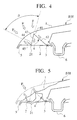
- the reinforcement 4 is substantially N-shaped and the first bending part 41 is shaped so as to be triangular by the walls 42, 43 meeting each other at angles, as shown in Figs. 2A, 2B,and 3. Further, the terminal of the rear wall 42 is welded to the inner panel 2, while the top of the second bending part 44 formed at the terminal of the wall 43 is engaged in the engaging part 21. Accordingly, as for the upper collision, the input can be ensurely transmitted to the inner panel 2,thereby accomplishing the buckling of the walls due to the occurrence of reactive force appropriately. Moreover, for not only collision load from the perpendicular direction to the outer panel 1 but also collision loads from various angles represented by arrows F of Fig. 4, the walls 42, 43 can buckle into deformation (see Fig. 5) thereby to carry out the energy absorption against various collisions from a wide angle ⁇ effectively.
- the wall 45 in front of the second bending part 44 is generally parallel to the wall 42 behind the first bending part 41, not only does the wall 45 buckle into deformation,thereby to enhance the energy absorbing effect, but also the occurrence area of reactive force is dispersed by the first bending part 41 and the wall 45, thereby to obtain the effect to reduce a moment.
- Fig. 8 shows a load/stroke diagram in case of the occurrence of collision of relatively large energy with the front part of the front hood from its obliquely upside with respect to the vehicle traveling direction.
- a line A designates an energy-absorbing characteristic of the front hood without the reinforcement 4, showing a load being elevated by the abutment of the outer panel against the bottom of the structure.
- a line B designates an energy-absorbing characteristic of the front hood with the reinforcement 4.
- the collision load is initially elevated owing to the beginning of the buckling of the reinforcement 4 and,thereafter, the load at the outer panel's contact with the bottom can be reduced owing to the energy-absorbing effect of the buckled reinforcement 4.
- the second bending part 44 is detached from the groove of the engaging part 21 simultaneously with the pressing of the inner panel 2.
- the reinforcement 4 is subjected to compressive deformation to fold the walls 45, 43, 42 in the vehicle fore-and-aft direction. In this way, before the contact of the reinforcement 4 with the hood lock 6 to cause a high reactive force, it is possible to accomplish ideal energy absorption exhibiting a reduced reactive force in the vehicle fore-and-aft direction.
- the compressive deformation of the reinforcement 4 in the vehicle fore-and-aft direction can be carried out more systematically.
- the reinforcement 4 comes into contact with the high-rigidness hood lock 6 to generate a high reactive force, owing to the structure where the rear end of the reinforcement 4, i.e. the terminal of the wall 42 is welded to the inner panel 2 in the vicinity of the front part of the hood lock 6. That is, against the front collision with a relatively large energy, the above front hood structure allows the reinforcement 4 to be buckled in the vehicle fore-and-aft direction, improving the energy absorbing efficiency.
- the embodiment it is possible to attain the ideal energy absorbing performance against both upper collision and front collision. Additionally, since the walls 42, 43 of the reinforcement 4 forming the energy absorbing mechanism are arranged to extend on both sides of the first bending part 41 with different inclining directions, it is possible to simplify the wide-angle arrangement of the walls 42, 43 and also possible to provide the reinforcement 4 with a compact structure.
- a generally horizontal flange 45a is formed on an upper end of the wall 45 in front of the second bending part 44.
- the hood structure has effects similar to those of the first embodiment.
- the flange 45a is buckled to produce the reactive force at the time of the whole contact of the reinforcement 4 with the hood lock 6 of high rigidness (see Fig. 10), thereby improving the energy absorbing efficiency furthermore.
- a length of the rear wall 42 forming the first bending part 41 is represented by "a”, a length of the front wall 43 of the first bending part 41 "b", a length from the hemming joint 5 at the front end of the inner panel 2 to the groove of the engaging part 21 "C 1 ", and a length from the groove to fixing part 3 of the rear wall behind the first bending part 41 "c 2 ", as shown in Fig. 11.
- the inner panel 2 can be prevented from interfering with the walls 42, 43 of the reinforcement 4, accomplishing the shrinkage of the reinforcement 4 in the fore-and-aft direction appropriately.
- the peak of the second bending part 44 of the reinforcement 4 engages in the groove of the engaging part 21 of the inner panel 2.
- the peak of the second bending part 44 may be glued to the inner panel 2 on the front side of the groove through a glutinous adhesive, such as mastic seals 72.
- the bonding of the second bending part 44 to the inner panel 44 through the mastic seals 72 allows to prevent the occurrence of noise at the vehicle's traveling. Additionally, even if the compressive collision load of the upward-and-downward direction is applied on the reinforcement 4 at the upside collision, there is no possibility that the peak of the second bending part 44 is detached from the groove of the engaging part 21, accomplishing the load transmission for the inner panel 2 surely.
- the mastic seals 72 can be peeled off the inner panel 2,thereby allowing the reinforcement 44 to be deformed compressively.
- Fig. 14 shows the fourth embodiment of the invention,where the reinforcement 4 is provided with the first bending parts 41 and the second bending parts 44 arranged alternately in the vehicle fore-and-aft direction, forming a W(or M)-shaped configuration in side view.
- Figs. 15 and 16 show the fifth embodiment where the present invention is applied to a so-called "slant-nose” type front hood having its front end rolling downward in front of the hood lock 6.
- the front part of the inner panel 2 has a horizontal part 2a extending from the hemming joint 5 toward the rear part of the vehicle horizontally and a rising part 2b rising from the rear end of the horizontal part 2a toward the hood lock 6 obliquely behind, providing a step structure.
- the energy absorbing mechanism is formed by a cut-and-raised structure 40.
- an opening 23 is formed so as to extend from the generally intermediate (in the fore-and-aft direction) part of the horizontal part 2a to the upper end of the rising part 2b.
- the cut-and-raised structure 40 includes a first bending part 41 projecting toward the outer panel 1 and a second bending part 44 connected to the first bending part 41 through the wall 43 to project toward the horizontal part 2a of the inner panel 2.
- the first bending part 41 is triangular-shaped by the front wall 43 and the rear wall 42.
- the rear wall 42 is not cut away from the inner panel 2, while the front wall 43 is cut off from the inner panel 2,thereby to define the second bending part 44.
- the inner panel 2 is provided, at a front end of the opening 23, with a claw part 22 for engagement with the second bending part 44.
- the wall 45 is formed so as to be generally parallel with the rear wall 42 of the first bending part 41.
- the cut-and-raised structure 40 may be provided,in a modification, as a plural.
- Fig. 16 shows an arrangement where two cut-and-raised structures 40 are formed in the vehicle width direction.
- Figs. 17A to 17D show the sixth embodiment of the invention,where the reinforcement 4 or the cut-and-raised structure 40 of the previous embodiments is provided, on the walls 42, 43 of the first bending part 41, with a bead 7c which induces the vertical buckling of the walls 42, 43 and beads 7a, 7b which induce the lateral buckling of the walls 42, 43.
- the front and rear walls 42, 43 of the first bending part 41 are shaped so as to be upward trapezoids in front view.
- the beads 7a, 7b for inducing the lateral buckling are formed so as to project upward and also converge each other as they approach the peak of the first bending part 41.
- the bead 7c for inducing the vertical buckling is formed so as to dent through the walls 43, 42 continuously.
- the walls 42, 43 are deformed in multi-stages by the beads 7a, 7b, 7c as the starting points of vertical and lateral buckling, whereby the energy absorption can be performed efficiently.
- the vertical buckling is firstly induced by the dented bead 7c extending through the walls 42, 43 and, thereafter, the vertical buckling is shifted to the lateral buckling since the upper end of the projecting bead 7a interferes with the upper end of the projecting bead 7b.
- the walls 42, 43 can be deformed from upside to downside in order,owing to the trapezoid configurations, accomplishing the energy absorption more effectively.
- Figs. 18A and 18B show the seventh embodiment of the invention.
- vertical walls 47a, 47b are formed on both ends of the front wall 43 in the vehicle width direction, through folding parts 46a, 46b, respectively.
- the vertical walls 47a, 47b may be provided on the rear wall 42.
- the seventh embodiment has effects similar to those of the first embodiment.
- the vertical walls 47a, 47b of the reinforcement 4 can be buckled in the fore-and-aft direction and the upward-and-downward direction respectively, accomplishing the energy absorption more effectively.
- Figs. 19A and 19B show the eighth embodiment,where the present structure is applied to the slant-nose type front hood F/H as shown in Figs. 15 and 16.
- the reinforcement 4 is arranged to extend over the horizontal part 2a and the rising part 2b of the inner panel 2.
- the reinforcement 4 has the first bending part 41 projecting toward the outer panel 1 and the second bending part 44 formed on the terminal of the rear wall 42 of the first bending part 41 to project toward the inner panel 2.
- the first bending part 41 is triangular-shaped in side view by the front wall 43 and the rear wall 42.
- the end of the front wall 43 is welded to the horizontal part 2a of the inner panel 2, providing the fixing part 3.
- the rising part 2b is provided with the engaging part 21 in the form of a bead projecting upward and also extending in the vehicle width direction.
- the top of the second bending part 44 is engaged with the engaging part 21.
- the reinforcement 4 has slits 4d extending from the second bending part 44 to provide a plurality of reinforcing elements 4a-4c in the vehicle width direction.
- the reinforcing elements 4a-4c are respectively established to have different ratios of the front wall 43 to the rear wall 42 in length.
- the reinforcing elements 4a-4c have the first bending parts 41 whose tops are offset in the fore-and-aft direction so as to follow the downward-fronting curved face of the outer panel 1.
- the eighth embodiment which is similar to the fifth embodiment of Figs. 15 and 16, since the respective walls 42, 43 of the first bending parts 41 are effectively buckled by the upside collision, it is possible to improve the energy absorbing efficiency of the front hood structure against the upside collision. While, when the vehicle has a front collision, then the second bending part 44 is detached from the engaging part 21. Consequently, the shrinkage of the structure 40 is attained without hindering the bending of the inner panel 2, whereby it is possible to improve the energy absorbing efficiency of the front hood structure against the front collision.
- the wide-angle shock absorbing area can be enlarged without being accompanied with the increased length of the reinforcement 4 in the fore-and-aft direction, accomplishing the effective energy absorption against the upside collision with a wider angle. Further, despite that the generating points of reactive forces are dispersed by the offsetting of the tops of the first bending parts 41, it is possible to enhance the reduction effect for the moment.
- the above-mentioned “offset" arrangement for the tops of the first bending parts 41 may be applied to the reinforcement 4 of the first embodiment while dividing it into the reinforcing elements 4a-4c.
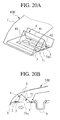
- Figs. 20A and 20B show the ninth embodiment of the invention.
- the reinforcement 4 is shaped to be triangular in side view, by the bending part 41 projecting toward the outer panel 1 and the walls 42, 43 before and behind the bending part 41.
- the front side of the inner panel 2 is shaped to be generally horizontal.
- the end of the front wall 43 is welded to this inner panel 2 in the vicinity of the hemming joint 5 at the front end of the hood, providing a fixing part 3.
- the end of the rear wall 42 is welded to the inner panel 2 in the vicinity of the front side of the hood lock 6, also providing a fixing part 3.
- the inner panel 2 is provided, between these fixing parts 3, 3, with a deformation-inducing part 71 which induces the inner panel 2 to be buckled by the front collision.
- the inner panel 2 has a plurality of long holes formed so as to adjoin in the vehicle width direction.
- the deformation-inducing part 71 may be provided by forming a downward bead 71b on the inner panel 2, extending in the vehicle width direction.
- the so-constructed hood structure has effects similar to those of the first embodiment.
- the walls 42, 43 interposing the bending part 41 are together welded to the inner panel 2, it is possible to ensure the transmission of input from the upside collision to the inner panel 2, realizing the appropriate occurrence of reactive forces.
- the front collision allows the inner panel 2 to be bent about the part 71 as the starting point of deformation.
- the shrinkage of the reinforcement 4 can be attained to exhibit the effectiveness of energy absorption against the front collision.
Landscapes
- Engineering & Computer Science (AREA)
- Mechanical Engineering (AREA)
- Superstructure Of Vehicle (AREA)
- Body Structure For Vehicles (AREA)
Applications Claiming Priority (4)
| Application Number | Priority Date | Filing Date | Title |
|---|---|---|---|
| JP2000020797 | 2000-01-28 | ||
| JP2000020797 | 2000-01-28 | ||
| JP2000356543A JP3873613B2 (ja) | 2000-01-28 | 2000-11-22 | 自動車用フロントフード構造およびこれを備えた自動車 |
| JP2000356543 | 2000-11-22 |
Publications (3)
| Publication Number | Publication Date |
|---|---|
| EP1120331A2 true EP1120331A2 (de) | 2001-08-01 |
| EP1120331A3 EP1120331A3 (de) | 2002-04-03 |
| EP1120331B1 EP1120331B1 (de) | 2003-12-10 |
Family
ID=26584417
Family Applications (1)
| Application Number | Title | Priority Date | Filing Date |
|---|---|---|---|
| EP01300604A Expired - Lifetime EP1120331B1 (de) | 2000-01-28 | 2001-01-24 | Fahrzeug-Motorhaube |
Country Status (3)
| Country | Link |
|---|---|
| EP (1) | EP1120331B1 (de) |
| JP (1) | JP3873613B2 (de) |
| DE (1) | DE60101394T2 (de) |
Cited By (4)
| Publication number | Priority date | Publication date | Assignee | Title |
|---|---|---|---|---|
| FR2836879A1 (fr) * | 2002-03-07 | 2003-09-12 | Peugeot Citroen Automobiles Sa | Vehicule automobile a securite renforcee en cas de choc pieton avant |
| EP2008884A1 (de) * | 2007-06-28 | 2008-12-31 | Ford Global Technologies, LLC | Motorhaube für Kraftfahrzeuge |
| DE102016015026A1 (de) | 2016-12-16 | 2017-07-06 | Daimler Ag | Beplankungselement für ein Fahrzeug. insbesondere für einen Personenkraftwagen |
| DE102017005003A1 (de) | 2016-06-07 | 2017-12-07 | Mazda Motor Corporation | Front-Fahrzeugkarosseriestruktur und Verfahren zum Absorbieren eines frontalen Aufpralls |
Families Citing this family (11)
| Publication number | Priority date | Publication date | Assignee | Title |
|---|---|---|---|---|
| JP4490983B2 (ja) * | 2007-03-02 | 2010-06-30 | 本田技研工業株式会社 | 車両のフロントウインドシールド支持構造 |
| KR100848735B1 (ko) * | 2007-07-19 | 2008-07-25 | 지엠대우오토앤테크놀로지주식회사 | 자동차의 엔진 후드패널 |
| JP2009040168A (ja) * | 2007-08-07 | 2009-02-26 | Kanto Auto Works Ltd | 車両フード構造 |
| JP5238638B2 (ja) * | 2009-08-10 | 2013-07-17 | 本田技研工業株式会社 | 車両用フード構造 |
| JP5484163B2 (ja) * | 2010-04-07 | 2014-05-07 | 本田技研工業株式会社 | 車両用歩行者保護装置 |
| JP5657705B2 (ja) * | 2011-01-11 | 2015-01-21 | 本田技研工業株式会社 | 自動車のフロントフード構造 |
| WO2014010472A1 (ja) * | 2012-07-09 | 2014-01-16 | 日産自動車株式会社 | 自動車用フード |
| KR101795070B1 (ko) | 2012-08-30 | 2017-11-07 | 현대자동차주식회사 | 보행자 상해 보호장치 |
| DE102012024636A1 (de) * | 2012-12-17 | 2014-06-18 | GM Global Technology Operations LLC (n. d. Ges. d. Staates Delaware) | Frontpartie für ein Kraftfahrzeug |
| JP6064170B2 (ja) * | 2013-07-03 | 2017-01-25 | トヨタ車体株式会社 | フードの前部構造 |
| JP6206394B2 (ja) * | 2014-12-26 | 2017-10-04 | トヨタ自動車株式会社 | 車体構造 |
Citations (2)
| Publication number | Priority date | Publication date | Assignee | Title |
|---|---|---|---|---|
| JPH107027A (ja) | 1996-06-26 | 1998-01-13 | Nissan Motor Co Ltd | 自動車用フロントフード |
| JP2000356543A (ja) | 1999-06-14 | 2000-12-26 | Yamato Scale Co Ltd | 定量供給装置 |
Family Cites Families (3)
| Publication number | Priority date | Publication date | Assignee | Title |
|---|---|---|---|---|
| JPS59156872A (ja) * | 1983-02-23 | 1984-09-06 | Nissan Motor Co Ltd | 自動車用フ−ド |
| DE3546050A1 (de) * | 1985-12-24 | 1987-07-02 | Ford Werke Ag | Kunststoffbauteil, insbesondere stossaufnehmendes karosserieaussenteil fuer kraftfahrzeuge |
| FR2621677B1 (fr) * | 1987-10-13 | 1990-06-22 | Heuliez Henri France Design | Structure rigide destinee a la realisation de panneaux ou d'elements tridimensionnels |
-
2000
- 2000-11-22 JP JP2000356543A patent/JP3873613B2/ja not_active Expired - Fee Related
-
2001
- 2001-01-24 DE DE60101394T patent/DE60101394T2/de not_active Expired - Lifetime
- 2001-01-24 EP EP01300604A patent/EP1120331B1/de not_active Expired - Lifetime
Patent Citations (2)
| Publication number | Priority date | Publication date | Assignee | Title |
|---|---|---|---|---|
| JPH107027A (ja) | 1996-06-26 | 1998-01-13 | Nissan Motor Co Ltd | 自動車用フロントフード |
| JP2000356543A (ja) | 1999-06-14 | 2000-12-26 | Yamato Scale Co Ltd | 定量供給装置 |
Cited By (6)
| Publication number | Priority date | Publication date | Assignee | Title |
|---|---|---|---|---|
| FR2836879A1 (fr) * | 2002-03-07 | 2003-09-12 | Peugeot Citroen Automobiles Sa | Vehicule automobile a securite renforcee en cas de choc pieton avant |
| EP2008884A1 (de) * | 2007-06-28 | 2008-12-31 | Ford Global Technologies, LLC | Motorhaube für Kraftfahrzeuge |
| DE102017005003A1 (de) | 2016-06-07 | 2017-12-07 | Mazda Motor Corporation | Front-Fahrzeugkarosseriestruktur und Verfahren zum Absorbieren eines frontalen Aufpralls |
| US10160418B2 (en) | 2016-06-07 | 2018-12-25 | Mazda Motor Corporation | Front vehicle-body structure |
| DE102017005003B4 (de) | 2016-06-07 | 2023-02-23 | Mazda Motor Corporation | Front-Fahrzeugkarosseriestruktur und Verfahren zum Absorbieren eines frontalen Aufpralls |
| DE102016015026A1 (de) | 2016-12-16 | 2017-07-06 | Daimler Ag | Beplankungselement für ein Fahrzeug. insbesondere für einen Personenkraftwagen |
Also Published As
| Publication number | Publication date |
|---|---|
| DE60101394T2 (de) | 2004-10-14 |
| JP3873613B2 (ja) | 2007-01-24 |
| EP1120331B1 (de) | 2003-12-10 |
| EP1120331A3 (de) | 2002-04-03 |
| JP2001278120A (ja) | 2001-10-10 |
| DE60101394D1 (de) | 2004-01-22 |
Similar Documents
| Publication | Publication Date | Title |
|---|---|---|
| EP1120331B1 (de) | Fahrzeug-Motorhaube | |
| US6726261B2 (en) | Bumper reinforcement | |
| JP3828329B2 (ja) | 自動車の車体構造 | |
| US6899195B2 (en) | Vehicle front structure | |
| US6938950B2 (en) | Vehicle body structure | |
| JP2005125989A (ja) | 車両用フード構造 | |
| JP2005145224A (ja) | 車両用フード構造 | |
| KR20040023489A (ko) | 자동차 차체의 전방부 구조 | |
| JP2003146242A (ja) | 車体前部構造 | |
| JP5251442B2 (ja) | 車両用フード構造 | |
| JP2005247119A (ja) | 車両用乗員膝部保護装置 | |
| JP3617481B2 (ja) | 自動車の車体前部構造 | |
| JP4032018B2 (ja) | 自動車の前部車体構造 | |
| JPH07228267A (ja) | 車体の強度部材構造 | |
| JP2003095135A (ja) | 自動車の車体前部構造 | |
| JP2005297857A (ja) | バンパーレインフォース構造 | |
| JP7472684B2 (ja) | 車両の前部車体構造 | |
| JPH0880873A (ja) | 自動車のフード | |
| CN121969540A (zh) | 车辆用碰撞能量吸收装置及车辆用碰撞能量吸收装置的制造方法 | |
| JP2002321643A (ja) | 自動車の車体前部構造 | |
| JP4362952B2 (ja) | バンパステイ | |
| EP1219529A2 (de) | Vorderwagenaufbau eines Fahrzeuges | |
| JP2006231965A (ja) | 車両前部構造 | |
| JP2002308144A (ja) | 車体骨格構造および車体の衝撃吸収方法 | |
| JP2003335266A (ja) | 車体骨格フレームの補強構造 |
Legal Events
| Date | Code | Title | Description |
|---|---|---|---|
| PUAI | Public reference made under article 153(3) epc to a published international application that has entered the european phase |
Free format text: ORIGINAL CODE: 0009012 |
|
| 17P | Request for examination filed |
Effective date: 20010208 |
|
| AK | Designated contracting states |
Kind code of ref document: A2 Designated state(s): DE FR GB Kind code of ref document: A2 Designated state(s): AT BE CH CY DE DK ES FI FR GB GR IE IT LI LU MC NL PT SE TR |
|
| AX | Request for extension of the european patent |
Free format text: AL;LT;LV;MK;RO;SI |
|
| PUAL | Search report despatched |
Free format text: ORIGINAL CODE: 0009013 |
|
| AK | Designated contracting states |
Kind code of ref document: A3 Designated state(s): AT BE CH CY DE DK ES FI FR GB GR IE IT LI LU MC NL PT SE TR |
|
| AX | Request for extension of the european patent |
Free format text: AL;LT;LV;MK;RO;SI |
|
| RIC1 | Information provided on ipc code assigned before grant |
Free format text: 7B 60R 21/34 A, 7B 60R 19/14 B, 7B 62D 25/10 B, 7B 62D 25/12 B |
|
| 17Q | First examination report despatched |
Effective date: 20021025 |
|
| AKX | Designation fees paid |
Free format text: DE FR GB |
|
| GRAH | Despatch of communication of intention to grant a patent |
Free format text: ORIGINAL CODE: EPIDOS IGRA |
|
| GRAS | Grant fee paid |
Free format text: ORIGINAL CODE: EPIDOSNIGR3 |
|
| GRAA | (expected) grant |
Free format text: ORIGINAL CODE: 0009210 |
|
| AK | Designated contracting states |
Kind code of ref document: B1 Designated state(s): DE FR GB |
|
| REG | Reference to a national code |
Ref country code: GB Ref legal event code: FG4D |
|
| REG | Reference to a national code |
Ref country code: IE Ref legal event code: FG4D |
|
| REF | Corresponds to: |
Ref document number: 60101394 Country of ref document: DE Date of ref document: 20040122 Kind code of ref document: P |
|
| ET | Fr: translation filed | ||
| PLBE | No opposition filed within time limit |
Free format text: ORIGINAL CODE: 0009261 |
|
| STAA | Information on the status of an ep patent application or granted ep patent |
Free format text: STATUS: NO OPPOSITION FILED WITHIN TIME LIMIT |
|
| REG | Reference to a national code |
Ref country code: IE Ref legal event code: MM4A |
|
| 26N | No opposition filed |
Effective date: 20040913 |
|
| PGFP | Annual fee paid to national office [announced via postgrant information from national office to epo] |
Ref country code: GB Payment date: 20090121 Year of fee payment: 9 |
|
| PGFP | Annual fee paid to national office [announced via postgrant information from national office to epo] |
Ref country code: FR Payment date: 20090113 Year of fee payment: 9 |
|
| PGFP | Annual fee paid to national office [announced via postgrant information from national office to epo] |
Ref country code: DE Payment date: 20100121 Year of fee payment: 10 |
|
| GBPC | Gb: european patent ceased through non-payment of renewal fee |
Effective date: 20100124 |
|
| REG | Reference to a national code |
Ref country code: FR Ref legal event code: ST Effective date: 20100930 |
|
| PG25 | Lapsed in a contracting state [announced via postgrant information from national office to epo] |
Ref country code: FR Free format text: LAPSE BECAUSE OF NON-PAYMENT OF DUE FEES Effective date: 20100201 |
|
| PG25 | Lapsed in a contracting state [announced via postgrant information from national office to epo] |
Ref country code: GB Free format text: LAPSE BECAUSE OF NON-PAYMENT OF DUE FEES Effective date: 20100124 |
|
| REG | Reference to a national code |
Ref country code: DE Ref legal event code: R119 Ref document number: 60101394 Country of ref document: DE Effective date: 20110802 |
|
| PG25 | Lapsed in a contracting state [announced via postgrant information from national office to epo] |
Ref country code: DE Free format text: LAPSE BECAUSE OF NON-PAYMENT OF DUE FEES Effective date: 20110802 |