EP1120603A2 - Gasbrenner mit mehreren Flamenringen - Google Patents
Gasbrenner mit mehreren Flamenringen Download PDFInfo
- Publication number
- EP1120603A2 EP1120603A2 EP01400042A EP01400042A EP1120603A2 EP 1120603 A2 EP1120603 A2 EP 1120603A2 EP 01400042 A EP01400042 A EP 01400042A EP 01400042 A EP01400042 A EP 01400042A EP 1120603 A2 EP1120603 A2 EP 1120603A2
- Authority
- EP
- European Patent Office
- Prior art keywords
- burner
- head
- central
- gas
- annular
- Prior art date
- Legal status (The legal status is an assumption and is not a legal conclusion. Google has not performed a legal analysis and makes no representation as to the accuracy of the status listed.)
- Granted
Links
Images


Classifications
-
- F—MECHANICAL ENGINEERING; LIGHTING; HEATING; WEAPONS; BLASTING
- F23—COMBUSTION APPARATUS; COMBUSTION PROCESSES
- F23D—BURNERS
- F23D14/00—Burners for combustion of a gas, e.g. of a gas stored under pressure as a liquid
- F23D14/02—Premix gas burners, i.e. in which gaseous fuel is mixed with combustion air upstream of the combustion zone
- F23D14/04—Premix gas burners, i.e. in which gaseous fuel is mixed with combustion air upstream of the combustion zone induction type, e.g. Bunsen burner
- F23D14/06—Premix gas burners, i.e. in which gaseous fuel is mixed with combustion air upstream of the combustion zone induction type, e.g. Bunsen burner with radial outlets at the burner head
- F23D14/065—Premix gas burners, i.e. in which gaseous fuel is mixed with combustion air upstream of the combustion zone induction type, e.g. Bunsen burner with radial outlets at the burner head with injector axis inclined to the burner head axis
-
- F—MECHANICAL ENGINEERING; LIGHTING; HEATING; WEAPONS; BLASTING
- F24—HEATING; RANGES; VENTILATING
- F24C—DOMESTIC STOVES OR RANGES ; DETAILS OF DOMESTIC STOVES OR RANGES, OF GENERAL APPLICATION
- F24C3/00—Stoves or ranges for gaseous fuels
- F24C3/08—Arrangement or mounting of burners
- F24C3/085—Arrangement or mounting of burners on ranges
-
- F—MECHANICAL ENGINEERING; LIGHTING; HEATING; WEAPONS; BLASTING
- F23—COMBUSTION APPARATUS; COMBUSTION PROCESSES
- F23D—BURNERS
- F23D2900/00—Special features of, or arrangements for burners using fluid fuels or solid fuels suspended in a carrier gas
- F23D2900/14—Special features of gas burners
- F23D2900/14062—Special features of gas burners for cooking ranges having multiple flame rings
Definitions
- the present invention relates to improvements brought to multiple crown gas burners of flames which are suitable for mounting on a plate above a cooking appliance, especially for use household, and which include a first central burner, having a ring of peripheral flames and minus a second burner, annular and surrounding at a distance the central burner, having at least one crown of flames.
- Such burners are used when a significant heating power is required and / or, conjunction with respective supply devices gas from the central and ring burners, when a modulation of the heating power, in location and in time, is required (Asian cuisine by example).
- crowns of flame provided with a central burner at one crown of flames and an annular burner provided with a outdoor flame crown or two crowns of flames, respectively interior and exterior.
- the invention therefore aims to provide a burner with multiple flame crowns of an improved type, whose structure is suitable to confer a level of modern security while remaining simple to manufacture with a number of component parts reduced to a minimum, and in addition with a relatively vertical development reduced allowing its installation as well on a conventional stove only on a hob.
- a multiple flame crown burner in which the all of the primary air required to operate the first burner, central, and second burner, annular, is brought respectively to the vicinity of the first and second gas injectors via paths located exclusively above the top plate of the appliance cooking; for this purpose, the primary air enters the annular space defined between the burner head outside and the top plate, cross the recesses side of the burner head support means outside and enters the burner body where it is mixed with the gas jet leaving the first injector feeding the central burner, while otherwise passes from said annular space directly above, by a side opening provided for this purpose, towards the entrance of the horizontal convergent-divergent duct where it is mixed with the gas jet leaving the second injector to the external burner supply.
- this secondary air is partly constituted by the ambient air surrounding the burners (crown of flames outside of the second burner, annular; crown of first burner, central), partly by a fraction of the air entering the annular space defined by the external burner head and the plate above, this fraction of air passing through the aforementioned lights, between the two central burners and annular and feeding the crown flames inside of the annular burner and, in part, the central burner flames.
- the burner with multiple crowns of flames with structural arrangements specific to provide air supply, primary and secondary, leading to preventing a repercussion of uses underlying parts of the cooking appliance on the flames, even at low speed, in other words to prevent a possible flame extinction, especially at low regime, during a violent closing of the door of a including the underlying oven.
- the horizontal Venturi arrangement for the supply of the external burner head and the Venturi directed upwards and formed, as shown further on, partly tubularly and partly radially horizontally, provides a burner of relatively low height suitable for mounting also well on a stove than on a hob.
- the central well of the interior burner head is directed substantially vertically and the axis of the first injector is substantially vertical.
- the central well of the burner head is expected interior and the first injector which is substantially thereto coaxial are inclined by about 15 to 20 ° relative to the vertical.
- the gas burner has a single annular chamber in the external burner head, which is bordered bilaterally by passages of flame, and that the second burner, annular, has two crowns of flame, the burner being of the three flame crown type.
- the support means of the external burner head are integral with said head of external burner and are constituted in the form general of a skirt projecting below under the below said head and a surrounding shoulder the central recess of the central region of said head burner.
- the annular chamber of the external burner head can be closed, top, by a removable annular cover placed on the side walls of the room.
- the first burner, central either with a long Venturi sufficient, that the central well of the burner head interior has a decreasing section in direction from the top, thus forming a first section of Venturi, tubular, and that the upper surface of the head interior burner surrounding the upper orifice of the well central define, together with a cover removable above it, a radial annular divergent forming a second section of Venturi, annular radial.
- the burner has a flame detection thermocouple and / or a electric ignition member and said thermocouple and / or ignition device are functionally associated with central burner.
- a burner arranged in accordance with the invention presents, thanks to its structure, a great flexibility according to the type of cooking appliance to equip.
- the external burner head can, depending on the case, be provided with a single crown of flames arranged either internally or externally or be provided with two flame crowns indoor and outdoor.
- the burners central and exterior can, depending on the case, either be connected to a common gas supply control, either be connected each to an individual control gas supply, which allows modulation flexible heating conditions in location and in time.
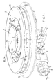
- the gas burner of the invention has a burner head interior 1, which is in the central position, having a peripheral flame crown (flame passages 2) and at least one external burner head 3, which is annular and remotely surrounds the central burner head 1, having at least one inner ring of flames and / or outdoor.
- the external burner head, annular, 3 has two flame crowns, one inside (flame passages 4) and the other exterior (passages of flames 5).
- the burner further includes a burner body 6 partially visible in Figures 1 and 2 and shown in isolation in FIG. 3.
- This burner body 6 has here a relatively elongated shape, substantially in correspondence with the diameter of the burner head exterior 3 which overcomes said body.
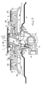
- the burner body 6 is designed to be fixed, by fixing means 7, under the top plate a cooking appliance, such as a stove, which top plate P is visible on the sectional drawings Figures 5, 6 and 7.
- a first gas inlet 8 connectable to a gas supply via control means (not shown) which are preferably their own.
- the gas supply 8 is in communication with a gas injector 9 located coaxially opposite one end of a conduit 10 first converge, then diverge and form Venturi tubular, which extends substantially over the largest part of the length of the burner body 6, i.e. the diameter of the outer burner head 3. Between the gas injector 9 and the conduit 10 is a light 11 for primary air intake. At its end terminal, line 10 is connected to a well substantially vertical 12 bringing the air-gas mixture into the external annular burner head 3.
- the burner body has a second gas inlet 13 distinct from the aforementioned first arrival 8, and arranged, here on the side of the body 6.
- the gas inlet 13 is connectable to a gas supply via means of controls (not shown) which are specific to it and are separate from the power control means of the first gas supply 8.
- the gas inlet 13 is in communication with a gas injector 14 which is directed upwards: at the Figure 6, the axis of the injector 14 is substantially vertical and substantially coaxial with the burner heads inside 1 and outside 3.
- the body of burner 5 supports accessories necessary for safe operation of the burner, and in particular at least a thermocouple Th and at least one ignition member electric Al.
- the external burner head 3 rests, through a cutout 30 made in the top plate P, on the burner body 6 by means of support.
- the burner body 6 has a support flange 16 overall circular located centrally and coaxially to the vertical injector 14.
- This flange 16 forms with the central bottom of the burner body 6 a kind of tank, having the injector 14 in its center and the means of outside burner head support arranged laterally.
- the means of support are secured to the underside of the burner head outside 3 and are formed in the form of a skirt 17 protruding downwards outwardly forming a peripheral shoulder 18 bearing on the top of the flange 16 above.
- This skirt 17 is made either of continuously with lights, either so discontinuous (case illustrated in Figure 6) in order to build 20 primary air passages like this will appear later.
- the lower edge of the skirt 17 is shaped to cooperate with projections 19 provided in the bottom of the tank, so as to block in rotation of the external burner head 3 on the body of burner 6 and serve simultaneously to position them mutually angularly correctly.
- the part of the external burner head 3 which surrounds the central region provided with the projecting skirt 17 overhangs the top plate P while being kept at a distance above of it, so the top plate P and the face bottom of burner head 3 define them an annular space 21, of irregular shape having regard to the general conformation of the burner.
- the aforementioned passages 20 communicate with this space 21.
- the external burner head 3 has a annular chamber 22 located near the periphery external of this head.
- Chamber 22 is formed by a channel defined by a bottom 23 and two side walls concentric 24, 25 and by a cover or cap annular 26 covering said channel.
- walls 24, 25 are formed notches forming flames.
- the two walls 24, 25 are provided with respective notches 4, 5, so that the outer burner head has a double crown of flames.
- the bottom 23 has an opening 27 facing the well substantially vertical 11 above.
- annular cap 26 is guided during its installation, and held in position by positioning fingers 28 integral with the external burner head 3.
- the head of external burner 3 is arranged so that between a central region which will be discussed below and the annular chamber 22, it has lights 29 which open this intermediate annular zone, for the purpose to allow air circulation as it will appear further.
- the central region 31 of the burner head outer 3 has a substantially vertical recess 32, coaxial with the axis of the injector 14.
- the central burner head 1 is supported peripherally on an annular shoulder 33 practiced in the external burner head 3. Its central region, projecting downwards, is engaged in the recess 32 above of the external burner head and has a central well 34 coaxial with the axis of the injector 14.
- the well 34 has a decreasing upward section and forms a convergent.
- the peripheral wall 35 of the burner head central 1 is pierced with notches 2 forming passages of flames.
- a cap or cover 36 rests on the wall 35.
- the facing faces of the cover 36 and the central region of the central burner head 1 which surrounds the orifice of the well 34 deviate substantially from each other radially outward, forming a radial annular divergent 37.
- the entire convergent tubular 34 and radial annular divergent 37 constitutes a Venturi.
- Figure 7 is shown a variant of realization of the arrangement illustrated in FIG. 6 and in which the central well 34 and the injector 14, coaxial, are no longer vertical, but tilted at an angle of 15 to 20 ° from the vertical.
- This arrangement is preferred in the vertical axis assembly of Figure 6, due to the elongation provided for well 34: although low, this extension is sufficient to improve the efficiency of the burner central 1.
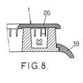
- the external burner head 3 is, as is often the case for burners with gas, bordered below by an annular skirt device 38 inclined downwards.
- This skirt can be integral part of burner head 3 as visible in particular in FIGS. 5, 6 and 7, or else may be a annular part 39 removably attached to the head burner 3: this annular part 39 can be put in place thanks to appropriate shoulders as illustrated, in partial sectional representation, in Figure 8.
- it then becomes easy to conform and / or decorate this annular part in various ways in order to satisfy for example business requirements.
Landscapes
- Engineering & Computer Science (AREA)
- Chemical & Material Sciences (AREA)
- Combustion & Propulsion (AREA)
- Mechanical Engineering (AREA)
- General Engineering & Computer Science (AREA)
- Gas Burners (AREA)
- Pre-Mixing And Non-Premixing Gas Burner (AREA)
Applications Claiming Priority (2)
| Application Number | Priority Date | Filing Date | Title |
|---|---|---|---|
| FR0001120 | 2000-01-28 | ||
| FR0001120A FR2804496B1 (fr) | 2000-01-28 | 2000-01-28 | Bruleur a gaz a multiples couronnes de flammes |
Publications (3)
| Publication Number | Publication Date |
|---|---|
| EP1120603A2 true EP1120603A2 (de) | 2001-08-01 |
| EP1120603A3 EP1120603A3 (de) | 2001-08-16 |
| EP1120603B1 EP1120603B1 (de) | 2005-07-27 |
Family
ID=8846429
Family Applications (1)
| Application Number | Title | Priority Date | Filing Date |
|---|---|---|---|
| EP01400042A Expired - Lifetime EP1120603B1 (de) | 2000-01-28 | 2001-01-09 | Gasbrenner mit mehreren Flamenringen |
Country Status (9)
| Country | Link |
|---|---|
| US (1) | US6325619B2 (de) |
| EP (1) | EP1120603B1 (de) |
| AT (1) | ATE300704T1 (de) |
| DE (1) | DE60112137T2 (de) |
| DK (1) | DK1120603T3 (de) |
| ES (1) | ES2245970T3 (de) |
| FR (1) | FR2804496B1 (de) |
| HK (1) | HK1038959A1 (de) |
| PT (1) | PT1120603E (de) |
Cited By (19)
| Publication number | Priority date | Publication date | Assignee | Title |
|---|---|---|---|---|
| DE20019731U1 (de) * | 2000-09-23 | 2001-12-13 | EGA Engineering GmbH, 58119 Hagen | Zweikreisbrenner mit Brennerring und Mittenbrenner |
| DE10315343A1 (de) * | 2003-04-03 | 2004-10-14 | Isphording Germany Gmbh | Gasbrenner mit Abdeckung |
| WO2008058934A1 (de) * | 2006-11-13 | 2008-05-22 | BSH Bosch und Siemens Hausgeräte GmbH | Gasbrenner |
| WO2008116773A3 (en) * | 2007-03-23 | 2009-04-16 | Defendi Italy Srl | Improved gas burner for cooking appliances |
| EP2053309A1 (de) * | 2007-10-23 | 2009-04-29 | Electrolux Home Products Corporation N.V. | Verbesserter Gasbrenner |
| EP2072895A1 (de) | 2007-12-18 | 2009-06-24 | Electrolux Home Products Corporation N.V. | Gasbrenner mit verbesserter primärer Luftleitung |
| US20100319677A1 (en) * | 2007-02-26 | 2010-12-23 | Indesit Company S.P.A. | Gas burner system for food cooking appliances |
| CN103742909A (zh) * | 2014-01-25 | 2014-04-23 | 浙江帅丰电器有限公司 | 一种具有双引射器的上进风燃烧器 |
| KR101476563B1 (ko) * | 2010-09-16 | 2014-12-24 | 로쉐 게엠베하 | 조절 범위가 연장된 고체 연소 고온 가스 발생기 |
| CN104713084A (zh) * | 2015-03-12 | 2015-06-17 | 广东美的厨房电器制造有限公司 | 燃烧器及燃气用具 |
| EP2226560A3 (de) * | 2009-03-06 | 2015-09-02 | Turas Gaz Armatürleri Sanayi. Ve Ticaret A.S. | Brenner für Gasherde mit mehreren Flammenringen |
| CN105546537A (zh) * | 2016-01-21 | 2016-05-04 | 广东海信家电有限公司 | 一种高效燃烧器及燃气灶 |
| CN105934633A (zh) * | 2014-01-14 | 2016-09-07 | 德芬迪意大利有限责任公司 | 用于烹饪搁架的气体燃烧器 |
| WO2017093615A1 (fr) | 2015-11-30 | 2017-06-08 | Sourdillon | Bruleur a gaz a multiples couronnes de flammes ayant deux venturis parallels, l'un au-dessus de l'autre |
| WO2018166067A1 (zh) * | 2017-03-15 | 2018-09-20 | 广东美的厨房电器制造有限公司 | 燃烧器和燃气灶具 |
| CN111735050A (zh) * | 2020-07-13 | 2020-10-02 | 佛山市顺德区美的洗涤电器制造有限公司 | 炉头、燃烧器及燃气灶具 |
| CN112268276A (zh) * | 2020-10-30 | 2021-01-26 | 陈毅 | 一种侧向斜喷型上进风炉头及其加工工艺 |
| CN113251417A (zh) * | 2021-05-28 | 2021-08-13 | 中山市樱雪集团有限公司 | 一种用于燃气灶的燃烧器 |
| CN113623652A (zh) * | 2021-09-17 | 2021-11-09 | 佛山市顺德区诚厚电器有限公司 | 一种高热效率的三环火炉头及燃烧器 |
Families Citing this family (88)
| Publication number | Priority date | Publication date | Assignee | Title |
|---|---|---|---|---|
| IT1318126B1 (it) * | 2000-07-06 | 2003-07-23 | Sabaf Spa | Bruciatore con separatore interno |
| JP3688234B2 (ja) * | 2001-11-19 | 2005-08-24 | リンナイ株式会社 | ガスこんろ |
| ITMI20020315A1 (it) * | 2002-02-18 | 2003-08-18 | Sabaf Spa | Piano di cottura in vetro temprato o altro materiale termicamente degradabile |
| DE10222641A1 (de) * | 2002-05-20 | 2003-12-04 | Isphording Germany Gmbh | Gasbrenner mit oberer Simmerflamme |
| HU227511B1 (hu) * | 2002-11-12 | 2011-07-28 | Sabaf Spa | Gázégõ gáztûzhelyekhez |
| JP3687098B2 (ja) * | 2002-12-11 | 2005-08-24 | 株式会社ノーリツ | 燃焼管及びこの燃焼管を備えたガス燃焼機器 |
| FR2858393B1 (fr) * | 2003-07-31 | 2005-09-30 | Lemdys | Receptacle pour bruleur a gaz a flamme interne, et ensemble de cuisson comprenant un tel receptacle et un tel bruleur |
| US7527495B2 (en) * | 2003-10-21 | 2009-05-05 | Burner Systems International, Inc. | Cooperating bridge burner system |
| MY147945A (en) * | 2004-02-02 | 2013-02-15 | Electrolux Ab | Gas burner |
| ITMC20040024A1 (it) * | 2004-02-13 | 2004-05-13 | So Mi Press Societa Metalli In | Doppio bruciatore per cucine a gas, del tipo a piu' corone concentriche di fiamme |
| KR101196106B1 (ko) * | 2004-07-09 | 2012-11-01 | 디펜디 이탈리아 에스.알.엘. | 다수의 화염 섹터를 포함하는 버너 |
| ITVE20040031A1 (it) | 2004-07-09 | 2004-10-09 | Ohg Defendi S R L | Bruciatore a piu' settori di fiamme. |
| US7291009B2 (en) * | 2004-09-08 | 2007-11-06 | General Electric Company | Dual stacked gas burner and a venturi for improving burner operation |
| MY144257A (en) * | 2004-10-28 | 2011-08-29 | Electrolux Ab | Improved cooking gas burner |
| US7594812B2 (en) * | 2005-01-17 | 2009-09-29 | SO. M. I Press - Societa′ Metalli Iniettati, SpA | Double burner for gas cookers, of the type provided with multiple concentric flame crowns |
| ITVE20050004A1 (it) * | 2005-01-20 | 2006-07-21 | Ohg Defendi S R L | Bruciatore a gas per apparecchiature di cottura. |
| ES2530675T3 (es) * | 2005-02-17 | 2015-03-04 | Electrolux Home Prod Corp | Quemador de gas |
| ITMC20050036A1 (it) * | 2005-04-29 | 2006-10-30 | So M I Press Societa Metalli Iniettati Spa | Doppio bruciatore per fornelli a gas, a piu' corone concentriche di fiamme, ad elevata potenza. |
| FR2889293B1 (fr) * | 2005-07-29 | 2009-12-18 | Burner Systems Int Bsi | Bruleur a gaz a multiples couronnes de flammes concentriques |
| US7661954B2 (en) * | 2005-09-13 | 2010-02-16 | Uwe Harneit | Gas burner |
| US20070131217A1 (en) * | 2005-12-08 | 2007-06-14 | Kiosky Chung | Burning set of barbecue stove |
| US8302593B2 (en) * | 2005-12-30 | 2012-11-06 | General Electric Company | Gas burner assembly including inner and outer burners and methods for implementing same |
| ITMI20060535A1 (it) * | 2006-03-23 | 2007-09-24 | Enzo Inzaghi | Bruciatore modulare per piastra di cottura |
| ITTO20060502A1 (it) * | 2006-07-10 | 2008-01-11 | Itw Ind Components Srl | Dispositivo di accensione di fuochi in un elettrodomestico, in particolare un piano cottura o barbecue |
| CN100425908C (zh) * | 2006-08-16 | 2008-10-15 | 胡志学 | 一种具有气配均衡的节能燃烧器 |
| US20080054102A1 (en) * | 2006-08-29 | 2008-03-06 | Yuan Fu Chang | Head for a precision ceramic gas cooker |
| DE102006053426A1 (de) * | 2006-11-13 | 2008-05-15 | BSH Bosch und Siemens Hausgeräte GmbH | Brennerring |
| US7628609B2 (en) | 2006-12-29 | 2009-12-08 | Electrolux Home Products, Inc. | Hub and spoke burner with flame stability |
| BRPI0703890A2 (pt) * | 2007-02-23 | 2010-08-31 | Mabe Mexico S De R L De C V | queimador para fogões a gás, configuracão de queimadores, método para controlar um conjunto de queimadores e porta para passagem de uma chama em um queimador |
| ITRN20070013A1 (it) * | 2007-02-27 | 2008-08-28 | Indesit Company Spa | Piano cottura. |
| EP2039996B1 (de) * | 2007-09-21 | 2014-08-06 | Electrolux Home Products Corporation N.V. | Gasbrenner für ein Kochfeld |
| KR101182530B1 (ko) * | 2007-12-14 | 2012-09-12 | 엘지전자 주식회사 | 탑버너 및 이를 포함하는 조리기기 |
| KR100936150B1 (ko) * | 2007-12-17 | 2010-01-12 | 엘지전자 주식회사 | 버너 및 이를 포함하는 조리기기 |
| US7802567B2 (en) * | 2007-12-19 | 2010-09-28 | General Electric Company | Device and method for a gas burner |
| US7614877B2 (en) * | 2007-12-20 | 2009-11-10 | General Electric Company | Device and method for a gas burner |
| US20090165777A1 (en) * | 2007-12-27 | 2009-07-02 | Paul Bryan Cadima | Gas burner |
| ES2389998T3 (es) | 2008-03-25 | 2012-11-05 | Electrolux Home Products Corporation N.V. | Encimera de cocción con quemador de gas mejorado |
| US8616193B2 (en) * | 2008-06-27 | 2013-12-31 | Electrolux Home Products, Inc. | Cooktop swirl burner |
| US8535052B2 (en) * | 2008-08-11 | 2013-09-17 | General Electric Company | Cap for a gas burner |
| ITVE20080070A1 (it) * | 2008-09-08 | 2010-03-09 | Defendi Italy Srl | Bruciatore a gas per apparecchi di cottura. |
| US8689779B2 (en) * | 2009-01-23 | 2014-04-08 | Bsh Bosch Und Siemens Hausgeraete Gmbh | Gas burner |
| ES2375855B1 (es) | 2009-01-26 | 2012-10-10 | Butsir S.L | Quemador doble de gas. |
| US8973569B2 (en) * | 2009-02-18 | 2015-03-10 | Electrolux Home Products, Inc. | Gas burner |
| PL2236921T3 (pl) * | 2009-03-18 | 2015-04-30 | Electrolux Home Products Corp Nv | Ulepszony palnik gazowy |
| WO2011026754A1 (de) * | 2009-09-04 | 2011-03-10 | BSH Bosch und Siemens Hausgeräte GmbH | Gasbrennereinrichtung und gaskochstelle |
| US8899972B2 (en) * | 2009-12-14 | 2014-12-02 | Electrolux Home Products, Inc. | Burner designed for wide range of input rates |
| MX345335B (es) * | 2009-12-18 | 2017-01-25 | Mabe S A De C V * | Quemador de tres sectores de flama. |
| DE102010006276A1 (de) | 2010-01-25 | 2011-07-28 | E.G.O. Elektro-Gerätebau GmbH, 75038 | Zweikreis-Brennersystem und Verfahren zum Betrieb eines solchen Zweikreis-Brennersystems |
| US8845326B2 (en) * | 2010-10-13 | 2014-09-30 | General Electric Company | Gas burner assembly |
| JP5276080B2 (ja) * | 2010-11-15 | 2013-08-28 | リンナイ株式会社 | ガスコンロ |
| PT2655966T (pt) * | 2010-12-22 | 2018-05-21 | Sabaf Spa | Queimador a gás |
| CN102116476B (zh) * | 2011-02-14 | 2013-02-13 | 杭州老板电器股份有限公司 | 一种高效节能环保型燃烧器 |
| DE102012000753A1 (de) | 2012-01-18 | 2013-07-18 | Ceramaspeed Inc. | Gasbrenner mit wenigstens drei Flammenkreisen |
| USD743531S1 (en) * | 2012-03-13 | 2015-11-17 | Electrolux Home Products Corporation N.V. | Burner assembly |
| DE102013105875A1 (de) * | 2013-06-06 | 2014-12-24 | Isofrost Gmbh | Gasbrenner |
| CN103423745B (zh) * | 2013-08-08 | 2015-11-18 | 浙江火星人厨具有限公司 | 燃气燃烧器 |
| US20150107577A1 (en) * | 2013-10-18 | 2015-04-23 | Lg Electronics Inc. | Burner |
| USD745321S1 (en) * | 2014-01-13 | 2015-12-15 | Jürgen Koch | Gas burner |
| KR102297799B1 (ko) * | 2014-12-17 | 2021-09-03 | 엘지전자 주식회사 | 버너 |
| KR102301481B1 (ko) * | 2014-12-17 | 2021-09-14 | 엘지전자 주식회사 | 버너 |
| CN104534471B (zh) * | 2014-12-25 | 2016-09-07 | 广东美的厨房电器制造有限公司 | 燃烧器和燃气灶 |
| CN104613475B (zh) * | 2014-12-25 | 2017-02-22 | 广东美的厨房电器制造有限公司 | 燃烧器和燃气灶 |
| CN104696963B (zh) * | 2015-03-13 | 2017-01-11 | 广东美的厨房电器制造有限公司 | 燃烧器 |
| WO2016170499A1 (en) * | 2015-04-24 | 2016-10-27 | Defendi Italy S.R.L. | Improved gas burner for cooking appliances |
| WO2017051364A2 (en) * | 2015-09-24 | 2017-03-30 | Defendi Italy S.R.L. | A gas burner with multiple rings of flames for cooking hobs |
| ITVE20150018A1 (it) | 2015-04-24 | 2016-10-24 | Ego Elektro Geraetebau Gmbh | Bruciatore a gas perfezionato per apparecchi di cottura. |
| US10228144B2 (en) | 2015-05-28 | 2019-03-12 | Whirlpool Corporation | Method of pan detection and cooktop adjustment for multiple heating sections |
| US9677768B2 (en) * | 2015-06-11 | 2017-06-13 | Haier Us Appliance Solutions, Inc. | Multi-ring gas burner |
| US9664394B2 (en) * | 2015-06-11 | 2017-05-30 | Haier Us Appliance Solutions, Inc. | Multi-ring gas burner |
| CA2934675A1 (en) | 2015-07-02 | 2017-01-02 | Mabe, S.A. De C.V. | Multi burner ovni |
| US10591157B1 (en) * | 2015-09-14 | 2020-03-17 | Burner Systems International, Inc. | Method of converting a burner with a dual use pot to single flow |
| ES2875035T3 (es) | 2015-11-26 | 2021-11-08 | Electrolux Appliances AB | Quemador de gas y placa que comprende un quemador de gas |
| US10222070B2 (en) * | 2016-01-15 | 2019-03-05 | Haier Us Appliance Solutions, Inc. | Gas burner assembly with a temperature sensor |
| CN108006618B (zh) * | 2017-06-23 | 2024-01-16 | 宁波方太厨具有限公司 | 一体式燃烧器 |
| US10739009B2 (en) * | 2017-12-14 | 2020-08-11 | Midea Group Co., Ltd. | Method and apparatus for distributing heat from a burner |
| US10724735B2 (en) | 2017-12-14 | 2020-07-28 | Midea Group Co., Ltd. | Method and apparatus for distributing heat from a burner |
| US11234557B2 (en) | 2018-03-14 | 2022-02-01 | Ashley Bryant | Stovetop cooking and grilling assembly |
| US11085645B2 (en) * | 2018-05-31 | 2021-08-10 | Haier Us Appliance Solutions, Inc. | Eductor for a gas cooktop appliance |
| CN111911922B (zh) * | 2019-05-09 | 2025-01-28 | 宁波方太厨具有限公司 | 一种上进风燃烧器 |
| CN110260320B (zh) * | 2019-06-26 | 2020-10-23 | 宁波方太厨具有限公司 | 一体式集热罩、灶具燃烧器以及灶具 |
| US11209171B1 (en) | 2020-06-30 | 2021-12-28 | Midea Group Co., Ltd. | Gas burner lighting via rotation |
| WO2022240373A2 (en) * | 2021-05-12 | 2022-11-17 | Liva Gaz Armaturleri Ve Endustriyel Mutfak Aksesuarlari Sanayi Ve Ticaret Limited Sirketi | Burner for gas stoves |
| US11940148B2 (en) | 2021-10-28 | 2024-03-26 | Electrolux Appliances Aktiebolag | Multi injection dual ring gas burner for domestic gas cooking units |
| KR102621868B1 (ko) * | 2022-02-19 | 2024-01-05 | 문성철 | 가스버너 |
| US12416404B2 (en) * | 2023-03-13 | 2025-09-16 | Haier Us Appliance Solutions, Inc. | Gas burner assembly and cooktop appliance |
| CN117433018B (zh) * | 2023-12-21 | 2024-04-05 | 佛山市宇煜五金有限公司 | 一种三环直喷燃烧器 |
| JP2025123110A (ja) * | 2024-02-09 | 2025-08-22 | リンナイ株式会社 | 親子バーナ並びに加熱調理器 |
| JP2025123109A (ja) * | 2024-02-09 | 2025-08-22 | リンナイ株式会社 | 親子バーナ並びに加熱調理器 |
Family Cites Families (11)
| Publication number | Priority date | Publication date | Assignee | Title |
|---|---|---|---|---|
| JPS5787516A (en) * | 1980-11-19 | 1982-06-01 | Matsushita Electric Ind Co Ltd | Portable stove burner |
| IT1232887B (it) * | 1989-07-27 | 1992-03-05 | Merloni Elettrodomestici Spa | Bruciatore di gas per cottura di alimenti |
| DE4125308C2 (de) * | 1991-07-31 | 2002-06-13 | Isphording Germany Gmbh | Gasbrenner |
| IT1250838B (it) * | 1991-09-26 | 1995-04-21 | Merloni Elettrodomestici Spa | Bruciatore di gas. |
| IT1268490B1 (it) * | 1993-07-16 | 1997-03-04 | Defendi Srl Off Mec | Bruciatore a gas a doppia corona particolarmente per piani di cottura ad incasso |
| GB2280743B (en) * | 1993-08-06 | 1997-03-19 | Tri Square Ind Co Ltd | Gas burner |
| IT1273115B (it) * | 1994-04-08 | 1997-07-04 | Merloni Elettrodomestici Spa | Bruciatore di gas ad assetto variabile e piano di cottura incorporante tale bruciatore |
| PT932797E (pt) * | 1996-09-19 | 2004-03-31 | Burner Systems Int Bsi | Queimador de gas em especial para aparelho culinario |
| IT1294585B1 (it) * | 1997-08-11 | 1999-04-12 | Defendi Srl Off Mec | Bruciatore a gas a piu' settori di fiamma. |
| US5842849A (en) * | 1997-09-05 | 1998-12-01 | Huang; Hsu-Sheng | Gas burner |
| DE19757733A1 (de) * | 1997-12-23 | 1999-06-24 | Bosch Siemens Hausgeraete | Gasbrenneranordnung |
-
2000
- 2000-01-28 FR FR0001120A patent/FR2804496B1/fr not_active Expired - Lifetime
-
2001
- 2001-01-09 DE DE60112137T patent/DE60112137T2/de not_active Expired - Fee Related
- 2001-01-09 AT AT01400042T patent/ATE300704T1/de not_active IP Right Cessation
- 2001-01-09 ES ES01400042T patent/ES2245970T3/es not_active Expired - Lifetime
- 2001-01-09 DK DK01400042T patent/DK1120603T3/da active
- 2001-01-09 EP EP01400042A patent/EP1120603B1/de not_active Expired - Lifetime
- 2001-01-09 PT PT01400042T patent/PT1120603E/pt unknown
- 2001-01-26 US US09/769,337 patent/US6325619B2/en not_active Expired - Lifetime
-
2002
- 2002-01-29 HK HK02100683.0A patent/HK1038959A1/zh unknown
Cited By (31)
| Publication number | Priority date | Publication date | Assignee | Title |
|---|---|---|---|---|
| DE20019731U1 (de) * | 2000-09-23 | 2001-12-13 | EGA Engineering GmbH, 58119 Hagen | Zweikreisbrenner mit Brennerring und Mittenbrenner |
| DE10315343A1 (de) * | 2003-04-03 | 2004-10-14 | Isphording Germany Gmbh | Gasbrenner mit Abdeckung |
| CN101535716B (zh) * | 2006-11-13 | 2012-07-04 | Bsh博施及西门子家用器具有限公司 | 气体燃烧器 |
| WO2008058934A1 (de) * | 2006-11-13 | 2008-05-22 | BSH Bosch und Siemens Hausgeräte GmbH | Gasbrenner |
| US8746229B2 (en) * | 2007-02-26 | 2014-06-10 | Indesit Company S.P.A. | Gas burner system for food cooking appliances |
| US20100319677A1 (en) * | 2007-02-26 | 2010-12-23 | Indesit Company S.P.A. | Gas burner system for food cooking appliances |
| WO2008116773A3 (en) * | 2007-03-23 | 2009-04-16 | Defendi Italy Srl | Improved gas burner for cooking appliances |
| US9127838B2 (en) | 2007-03-23 | 2015-09-08 | Defendi Italy S.R.L. | Gas burner for cooking appliances |
| KR101479807B1 (ko) * | 2007-10-23 | 2015-01-06 | 일렉트로룩스 홈 프로덕츠 코오포레이션 엔.브이. | 개선된 가스 버너 |
| EP2258982A3 (de) * | 2007-10-23 | 2015-08-26 | Electrolux Home Products Corporation N.V. | Verbesserter Gasbrenner |
| US8221116B2 (en) | 2007-10-23 | 2012-07-17 | Electrolux Home Products Corporation N.V. | Gas burner |
| AU2007355135B2 (en) * | 2007-10-23 | 2011-12-01 | Electrolux Home Products Corporation N.V. | Improved gas burner |
| EP2053309A1 (de) * | 2007-10-23 | 2009-04-29 | Electrolux Home Products Corporation N.V. | Verbesserter Gasbrenner |
| WO2009053125A1 (en) * | 2007-10-23 | 2009-04-30 | Electrolux Home Products Corporation N.V. | Improved gas burner |
| EP2072895A1 (de) | 2007-12-18 | 2009-06-24 | Electrolux Home Products Corporation N.V. | Gasbrenner mit verbesserter primärer Luftleitung |
| EP2226560A3 (de) * | 2009-03-06 | 2015-09-02 | Turas Gaz Armatürleri Sanayi. Ve Ticaret A.S. | Brenner für Gasherde mit mehreren Flammenringen |
| KR101476563B1 (ko) * | 2010-09-16 | 2014-12-24 | 로쉐 게엠베하 | 조절 범위가 연장된 고체 연소 고온 가스 발생기 |
| CN105934633B (zh) * | 2014-01-14 | 2019-01-22 | 德芬迪意大利有限责任公司 | 用于烹饪搁架的气体燃烧器 |
| CN105934633A (zh) * | 2014-01-14 | 2016-09-07 | 德芬迪意大利有限责任公司 | 用于烹饪搁架的气体燃烧器 |
| CN103742909A (zh) * | 2014-01-25 | 2014-04-23 | 浙江帅丰电器有限公司 | 一种具有双引射器的上进风燃烧器 |
| CN103742909B (zh) * | 2014-01-25 | 2017-02-08 | 浙江帅丰电器有限公司 | 一种具有双引射器的上进风燃烧器 |
| CN104713084A (zh) * | 2015-03-12 | 2015-06-17 | 广东美的厨房电器制造有限公司 | 燃烧器及燃气用具 |
| CN104713084B (zh) * | 2015-03-12 | 2017-10-27 | 广东美的厨房电器制造有限公司 | 燃烧器及燃气用具 |
| WO2017093615A1 (fr) | 2015-11-30 | 2017-06-08 | Sourdillon | Bruleur a gaz a multiples couronnes de flammes ayant deux venturis parallels, l'un au-dessus de l'autre |
| US10551057B2 (en) | 2015-11-30 | 2020-02-04 | Societe Nouvelle Sourdillon | Gas burner with multiple rings of flames having two parallel venturis, one above the other |
| CN105546537A (zh) * | 2016-01-21 | 2016-05-04 | 广东海信家电有限公司 | 一种高效燃烧器及燃气灶 |
| WO2018166067A1 (zh) * | 2017-03-15 | 2018-09-20 | 广东美的厨房电器制造有限公司 | 燃烧器和燃气灶具 |
| CN111735050A (zh) * | 2020-07-13 | 2020-10-02 | 佛山市顺德区美的洗涤电器制造有限公司 | 炉头、燃烧器及燃气灶具 |
| CN112268276A (zh) * | 2020-10-30 | 2021-01-26 | 陈毅 | 一种侧向斜喷型上进风炉头及其加工工艺 |
| CN113251417A (zh) * | 2021-05-28 | 2021-08-13 | 中山市樱雪集团有限公司 | 一种用于燃气灶的燃烧器 |
| CN113623652A (zh) * | 2021-09-17 | 2021-11-09 | 佛山市顺德区诚厚电器有限公司 | 一种高热效率的三环火炉头及燃烧器 |
Also Published As
| Publication number | Publication date |
|---|---|
| PT1120603E (pt) | 2005-11-30 |
| DK1120603T3 (da) | 2005-11-21 |
| ATE300704T1 (de) | 2005-08-15 |
| DE60112137T2 (de) | 2006-04-13 |
| EP1120603B1 (de) | 2005-07-27 |
| FR2804496B1 (fr) | 2002-07-19 |
| DE60112137D1 (de) | 2005-09-01 |
| US6325619B2 (en) | 2001-12-04 |
| FR2804496A1 (fr) | 2001-08-03 |
| HK1038959A1 (zh) | 2002-04-04 |
| EP1120603A3 (de) | 2001-08-16 |
| ES2245970T3 (es) | 2006-02-01 |
| US20010010897A1 (en) | 2001-08-02 |
Similar Documents
| Publication | Publication Date | Title |
|---|---|---|
| EP1120603B1 (de) | Gasbrenner mit mehreren Flamenringen | |
| EP1306616B1 (de) | Atmosphärischer Gasbrenner | |
| EP0125965B1 (de) | Brenner für gasförmigen Brennstoff mit eingebautem Zünd- und Sicherheitssystem | |
| CA2616133C (fr) | Bruleur a gaz a multiples couronnes de flammes concentriques | |
| EP2507554B1 (de) | Gasbrenner mit simmerplatte | |
| US7881593B2 (en) | Gas cooking appliance with removable burners and useable work area | |
| US5405263A (en) | Sealed gas burner assembly | |
| EP3384208B1 (de) | Gasbrenner mit mehreren ringen von flammen mit zwei parallelen, übereinander angeordneten venturis | |
| BE902029A (fr) | Bruleur a gaz pour fourneaux et plans de cuisson en general. | |
| MX2013014022A (es) | Metodo para convertir una disposicion de quemador de gas de parte superior abierta en una disposicion de quemador radiante infrarrojo. | |
| EP0581655A1 (de) | Gaskocher mit atmosphärischem Brenner | |
| FR2935780A1 (fr) | Four de cuisson a gaz encastrable | |
| EP1232364B1 (de) | Kochplatte | |
| EP0719987B1 (de) | Verbesserter Gaskocher | |
| KR100927328B1 (ko) | 버너 및 이를 포함하는 조리기기 | |
| KR200480491Y1 (ko) | 휴대 가스버너용 듀얼 가스 어댑터 | |
| KR20060098026A (ko) | 가스버너 | |
| EP0611920B1 (de) | Aus drei Teilen bestehender Gasbrenner mit Pilotflamme für Kochgeräte | |
| KR100938200B1 (ko) | 버너 및 이를 포함하는 조리기기 | |
| KR200315932Y1 (ko) | 가스레인지용 버너 | |
| FR2567251A1 (fr) | Rechaud de camping catalytique | |
| BE508715A (de) | ||
| CH177058A (fr) | Brûleur à gaz. | |
| FR2597198A1 (fr) | Fourneau de plein air a usage domestique | |
| FR2734889A3 (fr) | Bruleur a gaz pour appareils menagers |
Legal Events
| Date | Code | Title | Description |
|---|---|---|---|
| PUAI | Public reference made under article 153(3) epc to a published international application that has entered the european phase |
Free format text: ORIGINAL CODE: 0009012 |
|
| PUAL | Search report despatched |
Free format text: ORIGINAL CODE: 0009013 |
|
| AK | Designated contracting states |
Kind code of ref document: A2 Designated state(s): AT BE CH CY DE DK ES FI FR GB GR IE IT LI LU MC NL PT SE TR |
|
| AX | Request for extension of the european patent |
Free format text: AL;LT;LV;MK;RO;SI |
|
| AK | Designated contracting states |
Kind code of ref document: A3 Designated state(s): AT BE CH CY DE DK ES FI FR GB GR IE IT LI LU MC NL PT SE TR |
|
| AX | Request for extension of the european patent |
Free format text: AL;LT;LV;MK;RO;SI |
|
| 17P | Request for examination filed |
Effective date: 20010920 |
|
| AKX | Designation fees paid |
Free format text: AT BE CH CY DE DK ES FI FR GB GR IE IT LI LU MC NL PT SE TR |
|
| RAP1 | Party data changed (applicant data changed or rights of an application transferred) |
Owner name: BURNER SYSTEMS INTERNATIONAL (BSI) |
|
| 17Q | First examination report despatched |
Effective date: 20031009 |
|
| GRAP | Despatch of communication of intention to grant a patent |
Free format text: ORIGINAL CODE: EPIDOSNIGR1 |
|
| GRAS | Grant fee paid |
Free format text: ORIGINAL CODE: EPIDOSNIGR3 |
|
| GRAA | (expected) grant |
Free format text: ORIGINAL CODE: 0009210 |
|
| AK | Designated contracting states |
Kind code of ref document: B1 Designated state(s): AT BE CH CY DE DK ES FI FR GB GR IE IT LI LU MC NL PT SE TR |
|
| REG | Reference to a national code |
Ref country code: GB Ref legal event code: FG4D Free format text: NOT ENGLISH |
|
| REG | Reference to a national code |
Ref country code: CH Ref legal event code: EP |
|
| REG | Reference to a national code |
Ref country code: IE Ref legal event code: FG4D Free format text: LANGUAGE OF EP DOCUMENT: FRENCH |
|
| REF | Corresponds to: |
Ref document number: 60112137 Country of ref document: DE Date of ref document: 20050901 Kind code of ref document: P |
|
| REG | Reference to a national code |
Ref country code: CH Ref legal event code: NV Representative=s name: E. BLUM & CO. PATENTANWAELTE |
|
| GBT | Gb: translation of ep patent filed (gb section 77(6)(a)/1977) |
Effective date: 20051003 |
|
| REG | Reference to a national code |
Ref country code: SE Ref legal event code: TRGR |
|
| REG | Reference to a national code |
Ref country code: DK Ref legal event code: T3 |
|
| REG | Reference to a national code |
Ref country code: GR Ref legal event code: EP Ref document number: 20050403123 Country of ref document: GR |
|
| PG25 | Lapsed in a contracting state [announced via postgrant information from national office to epo] |
Ref country code: FI Free format text: LAPSE BECAUSE OF NON-PAYMENT OF DUE FEES Effective date: 20060109 Ref country code: CY Free format text: LAPSE BECAUSE OF NON-PAYMENT OF DUE FEES Effective date: 20060109 Ref country code: IE Free format text: LAPSE BECAUSE OF NON-PAYMENT OF DUE FEES Effective date: 20060109 Ref country code: AT Free format text: LAPSE BECAUSE OF NON-PAYMENT OF DUE FEES Effective date: 20060109 |
|
| PG25 | Lapsed in a contracting state [announced via postgrant information from national office to epo] |
Ref country code: SE Free format text: LAPSE BECAUSE OF NON-PAYMENT OF DUE FEES Effective date: 20060110 Ref country code: ES Free format text: LAPSE BECAUSE OF NON-PAYMENT OF DUE FEES Effective date: 20060110 |
|
| PG25 | Lapsed in a contracting state [announced via postgrant information from national office to epo] |
Ref country code: CH Free format text: LAPSE BECAUSE OF NON-PAYMENT OF DUE FEES Effective date: 20060131 Ref country code: DK Free format text: LAPSE BECAUSE OF NON-PAYMENT OF DUE FEES Effective date: 20060131 Ref country code: LU Free format text: LAPSE BECAUSE OF NON-PAYMENT OF DUE FEES Effective date: 20060131 Ref country code: MC Free format text: LAPSE BECAUSE OF NON-PAYMENT OF DUE FEES Effective date: 20060131 Ref country code: BE Free format text: LAPSE BECAUSE OF NON-PAYMENT OF DUE FEES Effective date: 20060131 Ref country code: LI Free format text: LAPSE BECAUSE OF NON-PAYMENT OF DUE FEES Effective date: 20060131 |
|
| REG | Reference to a national code |
Ref country code: ES Ref legal event code: FG2A Ref document number: 2245970 Country of ref document: ES Kind code of ref document: T3 |
|
| PLBE | No opposition filed within time limit |
Free format text: ORIGINAL CODE: 0009261 |
|
| STAA | Information on the status of an ep patent application or granted ep patent |
Free format text: STATUS: NO OPPOSITION FILED WITHIN TIME LIMIT |
|
| 26N | No opposition filed |
Effective date: 20060428 |
|
| PG25 | Lapsed in a contracting state [announced via postgrant information from national office to epo] |
Ref country code: DE Free format text: LAPSE BECAUSE OF NON-PAYMENT OF DUE FEES Effective date: 20060801 Ref country code: NL Free format text: LAPSE BECAUSE OF NON-PAYMENT OF DUE FEES Effective date: 20060801 |
|
| REG | Reference to a national code |
Ref country code: DK Ref legal event code: EBP |
|
| REG | Reference to a national code |
Ref country code: CH Ref legal event code: PL |
|
| EUG | Se: european patent has lapsed | ||
| NLV4 | Nl: lapsed or anulled due to non-payment of the annual fee |
Effective date: 20060801 |
|
| PG25 | Lapsed in a contracting state [announced via postgrant information from national office to epo] |
Ref country code: PT Free format text: LAPSE BECAUSE OF NON-PAYMENT OF DUE FEES Effective date: 20061010 |
|
| REG | Reference to a national code |
Ref country code: IE Ref legal event code: MM4A |
|
| REG | Reference to a national code |
Ref country code: PT Ref legal event code: MM4A Free format text: LAPSE DUE TO NON-PAYMENT OF FEES Effective date: 20061010 |
|
| REG | Reference to a national code |
Ref country code: ES Ref legal event code: FD2A Effective date: 20060110 |
|
| BERE | Be: lapsed |
Owner name: BURNER SYSTEMS INTERNATIONAL *BSI Effective date: 20060131 |
|
| REG | Reference to a national code |
Ref country code: HK Ref legal event code: WD Ref document number: 1038959 Country of ref document: HK |
|
| PG25 | Lapsed in a contracting state [announced via postgrant information from national office to epo] |
Ref country code: GR Free format text: LAPSE BECAUSE OF NON-PAYMENT OF DUE FEES Effective date: 20060802 |
|
| PG25 | Lapsed in a contracting state [announced via postgrant information from national office to epo] |
Ref country code: TR Free format text: LAPSE BECAUSE OF FAILURE TO SUBMIT A TRANSLATION OF THE DESCRIPTION OR TO PAY THE FEE WITHIN THE PRESCRIBED TIME-LIMIT Effective date: 20050727 |
|
| REG | Reference to a national code |
Ref country code: FR Ref legal event code: TP Owner name: BURNER SYSTEMS INTERNATIONAL (BSI), FR Effective date: 20120125 Ref country code: FR Ref legal event code: CD Owner name: BURNER SYSTEMS INTERNATIONAL (BSI), FR Effective date: 20120125 |
|
| REG | Reference to a national code |
Ref country code: GB Ref legal event code: 732E Free format text: REGISTERED BETWEEN 20120202 AND 20120208 |
|
| REG | Reference to a national code |
Ref country code: FR Ref legal event code: PLFP Year of fee payment: 16 |
|
| REG | Reference to a national code |
Ref country code: FR Ref legal event code: PLFP Year of fee payment: 17 |
|
| REG | Reference to a national code |
Ref country code: FR Ref legal event code: PLFP Year of fee payment: 18 |
|
| PGFP | Annual fee paid to national office [announced via postgrant information from national office to epo] |
Ref country code: FR Payment date: 20181213 Year of fee payment: 19 |
|
| PGFP | Annual fee paid to national office [announced via postgrant information from national office to epo] |
Ref country code: GB Payment date: 20190109 Year of fee payment: 19 Ref country code: IT Payment date: 20190121 Year of fee payment: 19 |
|
| GBPC | Gb: european patent ceased through non-payment of renewal fee |
Effective date: 20200109 |
|
| PG25 | Lapsed in a contracting state [announced via postgrant information from national office to epo] |
Ref country code: FR Free format text: LAPSE BECAUSE OF NON-PAYMENT OF DUE FEES Effective date: 20200131 Ref country code: GB Free format text: LAPSE BECAUSE OF NON-PAYMENT OF DUE FEES Effective date: 20200109 |
|
| PG25 | Lapsed in a contracting state [announced via postgrant information from national office to epo] |
Ref country code: IT Free format text: LAPSE BECAUSE OF NON-PAYMENT OF DUE FEES Effective date: 20200109 |