EP3384208B1 - Gasbrenner mit mehreren ringen von flammen mit zwei parallelen, übereinander angeordneten venturis - Google Patents
Gasbrenner mit mehreren ringen von flammen mit zwei parallelen, übereinander angeordneten venturis Download PDFInfo
- Publication number
- EP3384208B1 EP3384208B1 EP15807963.2A EP15807963A EP3384208B1 EP 3384208 B1 EP3384208 B1 EP 3384208B1 EP 15807963 A EP15807963 A EP 15807963A EP 3384208 B1 EP3384208 B1 EP 3384208B1
- Authority
- EP
- European Patent Office
- Prior art keywords
- burner
- gas
- pipe
- central
- annular
- Prior art date
- Legal status (The legal status is an assumption and is not a legal conclusion. Google has not performed a legal analysis and makes no representation as to the accuracy of the status listed.)
- Active
Links
Images



Classifications
-
- F—MECHANICAL ENGINEERING; LIGHTING; HEATING; WEAPONS; BLASTING
- F23—COMBUSTION APPARATUS; COMBUSTION PROCESSES
- F23D—BURNERS
- F23D14/00—Burners for combustion of a gas, e.g. of a gas stored under pressure as a liquid
- F23D14/02—Premix gas burners, i.e. in which gaseous fuel is mixed with combustion air upstream of the combustion zone
- F23D14/04—Premix gas burners, i.e. in which gaseous fuel is mixed with combustion air upstream of the combustion zone induction type, e.g. Bunsen burner
- F23D14/06—Premix gas burners, i.e. in which gaseous fuel is mixed with combustion air upstream of the combustion zone induction type, e.g. Bunsen burner with radial outlets at the burner head
- F23D14/065—Premix gas burners, i.e. in which gaseous fuel is mixed with combustion air upstream of the combustion zone induction type, e.g. Bunsen burner with radial outlets at the burner head with injector axis inclined to the burner head axis
-
- F—MECHANICAL ENGINEERING; LIGHTING; HEATING; WEAPONS; BLASTING
- F23—COMBUSTION APPARATUS; COMBUSTION PROCESSES
- F23D—BURNERS
- F23D14/00—Burners for combustion of a gas, e.g. of a gas stored under pressure as a liquid
- F23D14/02—Premix gas burners, i.e. in which gaseous fuel is mixed with combustion air upstream of the combustion zone
- F23D14/04—Premix gas burners, i.e. in which gaseous fuel is mixed with combustion air upstream of the combustion zone induction type, e.g. Bunsen burner
- F23D14/06—Premix gas burners, i.e. in which gaseous fuel is mixed with combustion air upstream of the combustion zone induction type, e.g. Bunsen burner with radial outlets at the burner head
-
- F—MECHANICAL ENGINEERING; LIGHTING; HEATING; WEAPONS; BLASTING
- F24—HEATING; RANGES; VENTILATING
- F24C—DOMESTIC STOVES OR RANGES ; DETAILS OF DOMESTIC STOVES OR RANGES, OF GENERAL APPLICATION
- F24C3/00—Stoves or ranges for gaseous fuels
- F24C3/08—Arrangement or mounting of burners
-
- F—MECHANICAL ENGINEERING; LIGHTING; HEATING; WEAPONS; BLASTING
- F23—COMBUSTION APPARATUS; COMBUSTION PROCESSES
- F23D—BURNERS
- F23D2900/00—Special features of, or arrangements for burners using fluid fuels or solid fuels suspended in a carrier gas
- F23D2900/14—Special features of gas burners
- F23D2900/14062—Special features of gas burners for cooking ranges having multiple flame rings
-
- F—MECHANICAL ENGINEERING; LIGHTING; HEATING; WEAPONS; BLASTING
- F24—HEATING; RANGES; VENTILATING
- F24C—DOMESTIC STOVES OR RANGES ; DETAILS OF DOMESTIC STOVES OR RANGES, OF GENERAL APPLICATION
- F24C3/00—Stoves or ranges for gaseous fuels
- F24C3/08—Arrangement or mounting of burners
- F24C3/085—Arrangement or mounting of burners on ranges
Definitions
- the invention relates to assemblies formed by a top plate of a cooking appliance, in particular for household use, and in particular to gas burners with multiple crowns of flames which are suitable for being mounted on such a plate.
- Such burners generally include a central burner and an annular burner, surrounding the central burner.
- Such burners are used when significant heating power is required and / or, in conjunction with respective gas supply devices for the central and annular burners, when modulation of the heating power is required (Asian cuisine by example).
- burners with multiple flame crowns provided with a central burner with a peripheral flame crown and an annular burner, surrounding the central burner, provided with one or two flame crowns: an inner flame crown and an outer flame crown.
- the annular burner may also have only one outer flame ring.
- the object of the invention is therefore to propose a gas burner with multiple flame crowns of an improved type, the structure of which is suitable for allowing it to be placed both on a conventional cooker and on a thin baking sheet. (less than 3 cm).
- a burner with multiple flame crowns is constituted in which the mixture of gas and air jets passing through the first Venturi and supplying the external burner head is also used to supply the internal burner head, because the Venturi supplying the interior burner head communicates with the Venturi of the exterior burner head. This optimizes the space occupied by the burner body.
- the length of the Venturi (and therefore the performance of the interior burner head) can be increased without affecting the vertical size of the assembly.
- the invention also relates to an assembly comprising at least one gas burner as defined above and a cooking plate.
- the axis of the first duct is positioned below the plate plane of the cooking plate and the axis of the second duct is positioned above the hob plate plane.
- the assembly has an occupancy height much lower than that of known assemblies.
- the second duct is enclosed between the cooking plate, on the one hand, and the central burner and the annular burner, on the other hand. Thanks to this arrangement, the second conduit is preserved from any introduction of dirt, which facilitates cleaning of the assembly.
- the assembly includes at least one primary air inlet located below the plate.
- the assembly includes a gas burner comprising an internal burner head 1 (or central burner), which is in the central position, having a peripheral flame crown (flame passages 2) and at least one external burner head 3 ( or annular burner), which is annular and remotely surrounds the central burner head 1, having at least one ring of flames, interior and / or exterior.
- the annular external burner head 3 has an external flame ring (flame passages 4).
- the interior 1 and exterior 3 burner heads are produced in one piece. This has the advantage of reducing the number of parts in the assembly according to the invention.
- the interior 1 and exterior 3 burner heads thus form a single piece which, by means of a burner body 6, is capable of being mounted on a cooking plate P.
- the cooking plate P is, for example a stove plate or a cooking plate. It is visible on the drawings of Figures 1 to 3 .
- the plate P extends substantially along a plane of the plate P1.
- the burner body 6 is visible in particular on the figures 1 , 2 and 4 .
- This burner body 6 has here a relatively elongated shape, substantially in correspondence with the diameter of the external burner head 3 which surmounts said body.
- the burner body 6 is arranged to be fixed, by fixing means, at least partially under the plate P from above a cooking appliance.
- the figure 4 shows in particular that the burner body 6 is bordered, at least partially at substantially mid-height, with a fixing flange 70, punctually having holes 71.
- the plate P has a cutout 72 corresponding substantially to the shape of the section of the burner body 6, to accommodate the burner body 6 ( figure 3 ).
- Holes 73 are also produced around the cutout 72. Some holes 73 come in vertical correspondence with the holes 71 of the flange 70 of the burner body when the latter is positioned in the cutout 71 of the plate p.
- Fixing means such as nuts and screws (not shown) placed in the holes 71 and 73, secure the burner body 6 to the plate P.
- a gas inlet 8 At one end of the burner body 6 is a gas inlet 8, which can be connected to a gas supply via control means (not shown) which are preferably specific to it.
- the gas inlet 8 is in communication with a gas injector 9 located coaxially opposite one end of a conduit 10 first convergent, then divergent and forming tubular Venturi, which extends substantially over the greater part of the length of the burner body 6, that is to say of the diameter of the outer burner head 3, along an axis parallel to the plane P1.
- the primary air intake lumen is supplied with air through a through opening 80 and / or through the opening 81 made through the burner body 6, in the vicinity of the gas injector 9.
- the burner body 6 is produced in two parts which can be assembled together.
- a first part 60 which comprises the conduit 10 and a part 61 which comprises a housing for the injector and which can be assembled at one end of the part 60, opposite the inlet of the conduit 10.
- the arrow F on the figure 4 shows the place where part 61 should be positioned in relation to part 60 to assemble them together.
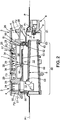
- the figure 2 shows that the end 62 of the part 60 is inserted into the end 62 of the part 61.
- parts 60 and 61 could be made in one piece.
- the duct 10 is in connection with a substantially vertical well 12 bringing the air-gas mixture into the external burner head 3.
- the burner body 6 comprises a second duct 5 forming a tubular Venturi, which extends parallel to the duct 10, also substantially over a part of the length of the burner body 6.
- the second duct 5 is disposed above the duct 10 and in opposite direction: the inlet 50 of the conduit 5 is from the well 12 and the outlet of the second conduit 5 is through an opening 51 made on the top of the conduit 5, near its end 52 opposite the end 53 comprising the inlet 50 of the second conduit 5.
- the second conduit 5 communicates with the well 12 and the air / gas mixture circulating in the conduit 12 is also sucked into the second conduit 5 in which it also circulates.
- the outlet opening 51 of the second conduit 5 opens into a corridor 54 which opens substantially at the center 59 of the central burner head 1, which makes it possible to conduct the air / gas mixture as far as the central burner head 1.
- the external burner head 3 comprises an annular chamber 22 located in the vicinity of the external periphery of this head.
- Chamber 22 is formed by a channel defined by a bottom 23 and two concentric side walls 24, 25 and by an annular cover or cap 26 covering said channel ( figure 1 ).
- In the wall 25 are made notches forming flame passages 4.
- the notches forming the flame passages are of different depths to allow better combustion and a non-fragile crown of flames.
- the bottom 23 of the chamber has an opening 27, which is positioned opposite the substantially vertical well 11 (above) of the burner body 6 when the assembly is assembled ( figure 2 ).
- annular cap 26 is guided, during its installation, and retained in position by positioning fingers 28 integral with the external burner head 3.
- the external burner head 3 is arranged so that between a central region which will be discussed later and the chamber annular 22, it includes lights 29 which open up this intermediate annular zone.
- the external burner head 3 is secured to the central burner head 1 at least by means of bridges 31 produced between the central burner head 1 and a positioning finger 28, secured to the concentric side wall 24 of the external burner head 3.
- the central interior burner head 1 has a central region, which has a central opening 34.
- the central opening coincides with the exit from the corridor 54 mentioned above, which makes it possible to guide the air / gas mixture leaving the second duct 5 towards a central region of the central interior burner head 1.
- the passage 54 is formed partially by the upper part of the burner body 6 having projections, and partially by a part of the central burner head assembled with the burner body 6.
- the figure 4 illustrating the burner body 6, shows a projecting part in the shape of a rectangle 55 provided on the upper part of the burner body 6.
- the solid bottom 56 of the interior space delimited by the projecting part in the shape of a rectangle 55 is produced by the wall of the burner body and it is situated substantially at the same level as that of the outlet end 51 of the second duct 5.
- the solid bottom 56 forms the bottom of the corridor 54.
- the side walls of the corridor 54 are formed in part by the projecting part in the shape of a rectangle 55, and by the side walls of a hollow part in the shape of a parallelepiped 57 which connects the side wall 24 of the external burner 3 and the internal burner 1 .
- the passage 54 is formed between the projecting part in the form of a rectangle 55 and the hollow part in the form of a parallelepiped 57.
- the central burner head 1 has a peripheral wall 35 which is pierced with notches 2, of different depths, forming flame passages (see figures 3 and 5 especially).
- a cap or cover 36 rests on the wall 35 (see figure 1 ).
- the external burner head 3 is, as is often the case for gas burners, bordered below by a peripheral annular skirt 38 inclined downwards.
- This skirt can be an integral part of the burner head 3, or it can be an annular piece attached removably to the burner head 3: this annular piece 38 can be put in place by means of suitable shoulders, for example.
- the burner body 6 when it is fixed to the plate P, occupies a space above the plate P and a space below the plate P, which further reduces the bulk of the body burner under the plate P and allows the burner body to be installed in very small spaces such as, for example, under a hob of reduced thickness (less than 3 cm).
- the arrows F1 show schematically the path followed by the primary air which, from the opening 80 (air coming from below the hob P) or from the upper end of the primary air intake lumen 11 (air arriving from above the cooking plate P), arrives at the inlet of the conduit 10 and simultaneously, passing through the well 12 and arrives at the conduit 5.
- thermocouple Th and / or a single electric ignition member Al are provided, which are then associated in operation with the single central burner.
- the burner body 6 has housings 74 and 75 in its fixing flange 70 to receive, respectively, at least one thermocouple Th and at least one electric ignition member Al.
- the second embodiment includes the same burner heads 1 and 3 made in one piece and the same plate P as the assembly shown in Figures 1 to 5 .
- the burner body 6 of this second example has special features that the burner body 6 of the first embodiment does not have and which will be developed now: As more easily visible to figures 6 and 7 , the burner body 6 in the second embodiment comprises a second gas inlet 13 distinct from the aforementioned first inlet 8, and arranged, here, on the side of the body 6, perpendicular to the axes of the two conduits 10 and 5.
- the gas inlet 13 can be connected to a gas supply via control means (not shown) which preferably are specific to it and are distinct from the control means for feeding the first gas inlet 8.
- the burner body 6 of the embodiment shown in Figures 1 to 5 also includes this second gas supply.
- the second arrival in the first embodiment is carried out by a blind hole.
- the well 12 of the burner body is not in communication with the second duct 5 in this second embodiment.
- the burner body 6 of the second embodiment and of the first embodiment can be produced by machining the same basic burner body: particular machining operations are thus carried out depending on whether one wishes to carry out a burner body with one or two gas inlets.
- the gas inlet 13 is in communication with a gas injector 14 which is directed parallel to the second Venturi 5, and therefore parallel to the first gas injector 9: at the figure 7 , the axis of the injector 14 is substantially horizontal and substantially parallel to the axes of the conduits 10 and 5.
- the gas injector 14 is positioned at one end of the second conduit 5 (end forming the inlet 50 of the conduit 5), opposite to the outlet 51 of the conduit 5 (the outlet 5 corresponds to the upward opening of the body of burner 6).
- the communication between the gas inlet 13 and the second gas injector 14 takes place by means of a conduit 15 pierced through the burner body 6, visible more particularly in figure 8 .
- the duct 15 is straight and has a first end 16 open in the gas inlet duct 13 and a second end 17 which opens at the rear of the second gas injector 14 (see figures 7 and 8 ).
- the second gas injector 14 is positioned in a cutout 18 made in the burner body 6 upstream of the second conduit 5 forming Venturi.
- the cutout 18 of the burner body 6 is placed under a second parallelepipedic part 58 connecting the two burner heads 1 and 3, the second parallelepipedic part 58 being in the extension of the first parallelepipedic part 57, according to the diameter of the head of external annular burner (see figure 7 ).
- the second parallelepiped part is produced by walls connecting the concentric side wall of the annular outer burner head 3 and the peripheral wall of the central inner burner head 1. Just like the first parallelepiped part 57, the second parallelepiped part 58 is open downwards so as to form a cover above the cutout 18 made in the burner body 6.
- the cutout 18 thus receives the gas injector 14 and allows a primary air intake F1 on either side of the injector 14 under the second rectangular part 58.
- the body of burner 6 forms a primary air intake chamber around the second injector 14 thanks to the cutout 18.
- the duct 15 which extends the second gas inlet 13 opens into the chamber d air intake in the vicinity of the second injector 14.
Landscapes
- Engineering & Computer Science (AREA)
- Chemical & Material Sciences (AREA)
- Combustion & Propulsion (AREA)
- Mechanical Engineering (AREA)
- General Engineering & Computer Science (AREA)
- Gas Burners (AREA)
Claims (16)
- Gasbrenner mit mehreren Ringen von Flammen, welcher geeignet ist, an einer oberen Platte (P) einer Kochvorrichtung, insbesondere für den Hausgebrauch, montiert zu sein, wobei sich die obere Platte (P) im Wesentlichen einer Plattenebene (P1) folgend erstreckt,
wobei der Gasbrenner umfasst:- einen zentralen Brenner (1), welcher einen Ring von umfänglichen Flammen besitzt, sowie wenigstens einen ringförmigen Brenner (3), welcher wenigstens einen Ring von umfänglichen Flammen besitzt, wobei der ringförmige Brenner (3) den zentralen Brenner umgibt,- und einen Brennerkörper (6), welcher geeignet ist, an der oberen Platte (P) befestigt zu sein,
wobei der Brennerkörper (6) wenigstens einen ersten Gaseingang (8) umfasst, welcher mit einem ersten Gasinjektor (9) kommuniziert, welcher zu einer ersten konvergent-divergenten Gasleitung (10) weist, welche ein Venturirohr bildet, wobei die erste Leitung (10) eine Achse aufweist, welche in der Lage ist, sich im Wesentlichen parallel zu der Plattenebene (P1) zu erstrecken, wobei sich die erste Leitung (10) wenigstens an dem größten Teil einer transversalen Erstreckung des Brennerkörpers (6) erstreckt, wobei die erste Leitung (10) an ihrem Ende gegenüber dem ersten Gasinjektor (9) in Kommunikation mit einem Schacht (12) ist, welcher im Wesentlichen senkrecht zu der Achse der ersten Leitung (10) ist, wobei der Schacht (12) nach oben offen ist und in der Lage ist, den ringförmigen Brenner (3) mit einem Luft/Gas-Gemisch zu versorgen,
wobei der Brennerkörper (6) eine zweite Leitung (5) umfasst, welche ein Venturirohr bildet, welche oberhalb der ersten Leitung (10) angeordnet ist, wobei die zweite Leitung (5) ein Ende (52) in Kommunikation mit einer Öffnung (51) zu der Oberseite des Brennerkörpers (6) aufweist, welche in der Lage ist, den zentralen Brenner (1) mit einem Luft/Gas-Gemisch zu versorgen,
dadurch gekennzeichnet, dass die Achse der zweiten Leitung (5) parallel zu der Achse der ersten Leitung (10) ist. - Gasbrenner nach Anspruch 1, dadurch gekennzeichnet, dass die zweite Leitung (5) ein zweites offenes Ende (53) in dem Schacht (12) derart umfasst, dass das Luft/Gas-Gemisch der ersten Leitung (10) ebenfalls in der zweiten Leitung (5) zirkuliert.
- Gasbrenner nach Anspruch 1, dadurch gekennzeichnet, dass der Brennerkörper (6) einen zweiten Gaseingang (13) umfasst, welcher mit einem zweiten Gasinjektor (14) kommuniziert, welcher zu der zweiten Leitung (5) weisend angeordnet ist, welche ein Venturirohr bildet, wobei der zweite Gasinjektor (14) an einem zweiten Ende der zweiten Leitung (5) positioniert ist, welche ein Venturirohr bildet, wobei das zweite Ende dem Ende (52) in Kommunikation mit der Öffnung (51) zu der Oberseite des Brennerkörpers (6) gegenüberliegt, wobei der zweite Gasinjektor (14) parallel zu dem ersten Gasinjektor (9) orientiert ist.
- Gasbrenner nach einem der vorhergehenden Ansprüche, dadurch gekennzeichnet, dass der zentrale Brenner (1) und der ringförmige Brenner (3) jeweils einen Kopf des zentralen Brenners (1) bzw. einen Kopf des ringförmigen Brenners (3) und einen Hut des zentralen Brenners (36) bzw. einen Hut des ringförmigen Brenners (26) umfassen.
- Gasbrenner nach Anspruch 4, dadurch gekennzeichnet, dass der Kopf des zentralen Brenners (1) und der Kopf des ringförmigen Brenners (3) als ein einzelnes Stück ausgebildet sind.
- Gasbrenner nach einem der Ansprüche 4 oder 5, dadurch gekennzeichnet, dass der Kopf des zentralen Brenners (1), welcher an dem Brennerkörper (6) angebracht ist, einen Durchgang (54) parallel zu der Achse der ersten und zweiten Leitungen (10, 5) bildet, welche Venturirohre bilden, wobei der Durchgang (54) einen Durchgangseingang (51), welcher durch die Öffnung (51) zu der Oberseite des Brenners (6) gebildet ist, sowie einen Durchgangsausgang aufweist, welcher im Wesentlichen im Zentrum (59) des Kopfs des zentralen Brenners (1) mündet.
- Gasbrenner nach einem der Ansprüche 4 bis 6, umfassend die Merkmale des Anspruchs 3, dadurch gekennzeichnet, dass stromaufwärts der zweiten Leitung (5), welche ein Venturirohr bildet, der Brennerkopf (5) mit dem Kopf des zentralen Brenners (1) eine Einlasskammer für Luft (18) um den zweiten Gasinjektor (14) herum bildet.
- Gasbrenner nach den Ansprüchen 3 und 7, dadurch gekennzeichnet, dass der zweite Gaseingang (13) in die Einlasskammer für Luft (18) in der Nähe des zweiten Gasinjektors (14) mündet.
- Gasbrenner nach einem der Ansprüche 4 bis 7, dadurch gekennzeichnet, dass der Kopf des ringförmigen Brenners (3) eine ringförmige Kammer (22) umfasst, welche wenigstens einseitig durch Flammendurchgänge (4) eingefasst ist und an ihren Boden (23) eine Öffnung (27) in Kommunikation mit dem Schacht (12) umfasst,
und dadurch, dass der Kopf des zentralen Brenners (1) eine Kammer des zentralen Brenners umfasst, welche eine Öffnung (59) umfasst, welche in der Lage ist, mit der Öffnung (51) zu der Oberseite des Brennerkörpers (6) zu kommunizieren. - Gasbrenner nach einem der vorhergehenden Ansprüche, dadurch gekennzeichnet, dass in der Nähe des wenigstens einen ersten Gaseingangs (8) der Brennerkörper (6) eine Einlassöffnung für Luft (80) in der Nähe des Eingangs der ersten Leitung (10) umfasst, welche ein Venturirohr bildet.
- Gasbrenner nach einem der vorhergehenden Ansprüche, dadurch gekennzeichnet, dass der ringförmige Brenner (3) unten durch einen Umfangskragen (38) umgeben ist, welcher in Richtung der Unterseite geneigt ist, wobei der Umfangskragen (38) vorzugsweise abnehmbar ausgeführt ist.
- Gasbrenner nach einem der vorhergehenden Ansprüche, dadurch gekennzeichnet, dass er wenigstens ein Thermoelement (Th) zum Detektieren eines Vorliegens von Flammen und/oder wenigstens eine elektrische Zündeinrichtung (A I) umfasst, und dadurch, dass das wenigstens eine Thermoelement (Th) und/oder die wenigstens eine elektrische Zündeinrichtung (A I) funktionell dem zentralen Brenner (1) zugeordnet sind.
- Anordnung, umfassend wenigstens einen Gasbrenner nach einem der vorhergehenden Ansprüche und eine Kochplatte (P).
- Anordnung nach Anspruch 13, dadurch gekennzeichnet, dass die Achse der ersten Leitung (10) unterhalb der Plattenebene (P1) der Kochplatte (P) positioniert ist, und dadurch, dass die Achse der zweiten Leitung (5) oberhalb der Plattenebene (P1) der Kochplatte (P) positioniert ist.
- Anordnung nach Anspruch 14, dadurch gekennzeichnet, dass die zweite Leitung zwischen der Kochplatte (P) einerseits und dem zentralen Brenner (1) und dem ringförmigen Brenner (3) andererseits eingeschlossen ist.
- Anordnung nach einem der Ansprüche 13 bis 15, dadurch gekennzeichnet, dass sie wenigstens einen primären Lufteingang umfasst, welcher unterhalb der Platte angeordnet ist.
Applications Claiming Priority (1)
| Application Number | Priority Date | Filing Date | Title |
|---|---|---|---|
| PCT/FR2015/053260 WO2017093615A1 (fr) | 2015-11-30 | 2015-11-30 | Bruleur a gaz a multiples couronnes de flammes ayant deux venturis parallels, l'un au-dessus de l'autre |
Publications (2)
| Publication Number | Publication Date |
|---|---|
| EP3384208A1 EP3384208A1 (de) | 2018-10-10 |
| EP3384208B1 true EP3384208B1 (de) | 2020-03-04 |
Family
ID=54848848
Family Applications (1)
| Application Number | Title | Priority Date | Filing Date |
|---|---|---|---|
| EP15807963.2A Active EP3384208B1 (de) | 2015-11-30 | 2015-11-30 | Gasbrenner mit mehreren ringen von flammen mit zwei parallelen, übereinander angeordneten venturis |
Country Status (4)
| Country | Link |
|---|---|
| US (1) | US10551057B2 (de) |
| EP (1) | EP3384208B1 (de) |
| ES (1) | ES2805468T3 (de) |
| WO (1) | WO2017093615A1 (de) |
Families Citing this family (7)
| Publication number | Priority date | Publication date | Assignee | Title |
|---|---|---|---|---|
| TR201702673A2 (tr) * | 2017-02-22 | 2018-09-21 | Arcelik As | Bi̇r bek grubu |
| US11085645B2 (en) * | 2018-05-31 | 2021-08-10 | Haier Us Appliance Solutions, Inc. | Eductor for a gas cooktop appliance |
| CN110242958A (zh) * | 2019-06-12 | 2019-09-17 | 佛山市顺德区美的洗涤电器制造有限公司 | 燃烧器的炉头、燃烧器和燃气灶具 |
| WO2021006829A1 (en) * | 2019-07-10 | 2021-01-14 | Femas Metal San. Ve Tic. A.S. | Burner assembly for a gas cooking device |
| TWI716949B (zh) * | 2019-07-30 | 2021-01-21 | 關隆股份有限公司 | 瓦斯爐之爐頭 |
| CN114198779A (zh) * | 2020-09-17 | 2022-03-18 | 宁波方太厨具有限公司 | 一种燃气灶具 |
| CN115585459B (zh) * | 2022-11-10 | 2026-04-28 | 中山市跃龙厨房电器有限公司 | 一种灶具上进风燃烧器 |
Family Cites Families (4)
| Publication number | Priority date | Publication date | Assignee | Title |
|---|---|---|---|---|
| CH177397A (fr) | 1934-09-03 | 1935-05-31 | Const D App A Gaz S A | Appareil de chauffage à gaz. |
| GB8824575D0 (en) * | 1988-10-20 | 1988-11-23 | Airoil Flaregas Ltd | Improvements in burner assemblies |
| FR2804496B1 (fr) | 2000-01-28 | 2002-07-19 | Sourdillon Sa | Bruleur a gaz a multiples couronnes de flammes |
| EP2258982B1 (de) | 2007-10-23 | 2019-01-16 | Electrolux Home Products Corporation N.V. | Verbesserter gasbrenner |
-
2015
- 2015-11-30 ES ES15807963T patent/ES2805468T3/es active Active
- 2015-11-30 EP EP15807963.2A patent/EP3384208B1/de active Active
- 2015-11-30 US US15/780,127 patent/US10551057B2/en active Active
- 2015-11-30 WO PCT/FR2015/053260 patent/WO2017093615A1/fr not_active Ceased
Non-Patent Citations (1)
| Title |
|---|
| None * |
Also Published As
| Publication number | Publication date |
|---|---|
| WO2017093615A1 (fr) | 2017-06-08 |
| US10551057B2 (en) | 2020-02-04 |
| US20180347808A1 (en) | 2018-12-06 |
| EP3384208A1 (de) | 2018-10-10 |
| ES2805468T3 (es) | 2021-02-12 |
Similar Documents
| Publication | Publication Date | Title |
|---|---|---|
| EP3384208B1 (de) | Gasbrenner mit mehreren ringen von flammen mit zwei parallelen, übereinander angeordneten venturis | |
| EP1120603B1 (de) | Gasbrenner mit mehreren Flamenringen | |
| CA2616133C (fr) | Bruleur a gaz a multiples couronnes de flammes concentriques | |
| EP1431658B1 (de) | Kompakter Gasbrenner mit inneren Flammen | |
| FR2545196A1 (fr) | Bruleur pour combustibles gazeux a systemes d'allumage et de securite incorpores | |
| FR2831242A1 (fr) | Bruleur a gaz de type atmospherique | |
| EP0719982A1 (de) | Gasbrenner für Kochfeld, Kochherd oder dergleichen | |
| EP2037174A1 (de) | Handwerkzeug mit verbesserter Gasverbrennung | |
| EP0509882A1 (de) | Stabbrenner | |
| EP1640663A2 (de) | Verbesserter Gasbrenner mit nur interner Flamme | |
| EP1099904B1 (de) | Hauskochfeldgasbrenner | |
| EP0679839A1 (de) | Verbesserungen an Gasbrennern | |
| EP1099905A1 (de) | Hauskochfeldgasbrenner | |
| EP0679838B1 (de) | Verbesserungen an Gasbrennern | |
| BE677134A (de) | ||
| EP3158265A1 (de) | Gasherd mit beleuchtungssystem für zwei brenner | |
| EP4519605B1 (de) | Oberflächenverbrennbarer und explosionsgeschützter gasbrenner | |
| FR3105999A1 (fr) | Robinet d’alimentation de gaz ameliore pour bruleur d’un appareil de cuisson a gaz | |
| EP2568217B1 (de) | Strahlrohr für Handwerkzeug, das sich ohne Temperaturdispersion entlang des Rohrs aufheizt | |
| EP4607091A1 (de) | Brenner für gaskocher oder gaskocher | |
| EP3372899B1 (de) | Herd mit multilateraler sicht des herdfeuers | |
| EP3845808A1 (de) | Gaszufuhrsystem, das mit einem elektrischen sicherheitsventil ausgestattet ist | |
| FR3048488B1 (fr) | Installation de chauffage pour un batiment | |
| FR2734889A3 (fr) | Bruleur a gaz pour appareils menagers | |
| FR2855868A1 (fr) | Bruleur a gaz perfectionne comportant des moyens de commande thermoelectrique incluant un thermocouple interne |
Legal Events
| Date | Code | Title | Description |
|---|---|---|---|
| STAA | Information on the status of an ep patent application or granted ep patent |
Free format text: STATUS: THE INTERNATIONAL PUBLICATION HAS BEEN MADE |
|
| PUAI | Public reference made under article 153(3) epc to a published international application that has entered the european phase |
Free format text: ORIGINAL CODE: 0009012 |
|
| STAA | Information on the status of an ep patent application or granted ep patent |
Free format text: STATUS: REQUEST FOR EXAMINATION WAS MADE |
|
| 17P | Request for examination filed |
Effective date: 20180509 |
|
| AK | Designated contracting states |
Kind code of ref document: A1 Designated state(s): AL AT BE BG CH CY CZ DE DK EE ES FI FR GB GR HR HU IE IS IT LI LT LU LV MC MK MT NL NO PL PT RO RS SE SI SK SM TR |
|
| AX | Request for extension of the european patent |
Extension state: BA ME |
|
| RAP1 | Party data changed (applicant data changed or rights of an application transferred) |
Owner name: SOCIETE NOUVELLE SOURDILLON |
|
| DAV | Request for validation of the european patent (deleted) | ||
| DAX | Request for extension of the european patent (deleted) | ||
| GRAP | Despatch of communication of intention to grant a patent |
Free format text: ORIGINAL CODE: EPIDOSNIGR1 |
|
| STAA | Information on the status of an ep patent application or granted ep patent |
Free format text: STATUS: GRANT OF PATENT IS INTENDED |
|
| INTG | Intention to grant announced |
Effective date: 20190329 |
|
| RIN1 | Information on inventor provided before grant (corrected) |
Inventor name: MEREAU, FABIENNE Inventor name: TROCHOU, CHRISTOPHE Inventor name: MONGAY, GILLES |
|
| GRAJ | Information related to disapproval of communication of intention to grant by the applicant or resumption of examination proceedings by the epo deleted |
Free format text: ORIGINAL CODE: EPIDOSDIGR1 |
|
| STAA | Information on the status of an ep patent application or granted ep patent |
Free format text: STATUS: REQUEST FOR EXAMINATION WAS MADE |
|
| INTC | Intention to grant announced (deleted) | ||
| GRAP | Despatch of communication of intention to grant a patent |
Free format text: ORIGINAL CODE: EPIDOSNIGR1 |
|
| STAA | Information on the status of an ep patent application or granted ep patent |
Free format text: STATUS: GRANT OF PATENT IS INTENDED |
|
| INTG | Intention to grant announced |
Effective date: 20190923 |
|
| GRAS | Grant fee paid |
Free format text: ORIGINAL CODE: EPIDOSNIGR3 |
|
| GRAA | (expected) grant |
Free format text: ORIGINAL CODE: 0009210 |
|
| STAA | Information on the status of an ep patent application or granted ep patent |
Free format text: STATUS: THE PATENT HAS BEEN GRANTED |
|
| AK | Designated contracting states |
Kind code of ref document: B1 Designated state(s): AL AT BE BG CH CY CZ DE DK EE ES FI FR GB GR HR HU IE IS IT LI LT LU LV MC MK MT NL NO PL PT RO RS SE SI SK SM TR |
|
| REG | Reference to a national code |
Ref country code: GB Ref legal event code: FG4D Free format text: NOT ENGLISH |
|
| REG | Reference to a national code |
Ref country code: CH Ref legal event code: EP |
|
| REG | Reference to a national code |
Ref country code: AT Ref legal event code: REF Ref document number: 1240802 Country of ref document: AT Kind code of ref document: T Effective date: 20200315 |
|
| REG | Reference to a national code |
Ref country code: DE Ref legal event code: R096 Ref document number: 602015048270 Country of ref document: DE |
|
| REG | Reference to a national code |
Ref country code: IE Ref legal event code: FG4D Free format text: LANGUAGE OF EP DOCUMENT: FRENCH |
|
| PG25 | Lapsed in a contracting state [announced via postgrant information from national office to epo] |
Ref country code: RS Free format text: LAPSE BECAUSE OF FAILURE TO SUBMIT A TRANSLATION OF THE DESCRIPTION OR TO PAY THE FEE WITHIN THE PRESCRIBED TIME-LIMIT Effective date: 20200304 Ref country code: NO Free format text: LAPSE BECAUSE OF FAILURE TO SUBMIT A TRANSLATION OF THE DESCRIPTION OR TO PAY THE FEE WITHIN THE PRESCRIBED TIME-LIMIT Effective date: 20200604 Ref country code: FI Free format text: LAPSE BECAUSE OF FAILURE TO SUBMIT A TRANSLATION OF THE DESCRIPTION OR TO PAY THE FEE WITHIN THE PRESCRIBED TIME-LIMIT Effective date: 20200304 |
|
| REG | Reference to a national code |
Ref country code: NL Ref legal event code: MP Effective date: 20200304 |
|
| PG25 | Lapsed in a contracting state [announced via postgrant information from national office to epo] |
Ref country code: SE Free format text: LAPSE BECAUSE OF FAILURE TO SUBMIT A TRANSLATION OF THE DESCRIPTION OR TO PAY THE FEE WITHIN THE PRESCRIBED TIME-LIMIT Effective date: 20200304 Ref country code: LV Free format text: LAPSE BECAUSE OF FAILURE TO SUBMIT A TRANSLATION OF THE DESCRIPTION OR TO PAY THE FEE WITHIN THE PRESCRIBED TIME-LIMIT Effective date: 20200304 Ref country code: GR Free format text: LAPSE BECAUSE OF FAILURE TO SUBMIT A TRANSLATION OF THE DESCRIPTION OR TO PAY THE FEE WITHIN THE PRESCRIBED TIME-LIMIT Effective date: 20200605 Ref country code: HR Free format text: LAPSE BECAUSE OF FAILURE TO SUBMIT A TRANSLATION OF THE DESCRIPTION OR TO PAY THE FEE WITHIN THE PRESCRIBED TIME-LIMIT Effective date: 20200304 Ref country code: BG Free format text: LAPSE BECAUSE OF FAILURE TO SUBMIT A TRANSLATION OF THE DESCRIPTION OR TO PAY THE FEE WITHIN THE PRESCRIBED TIME-LIMIT Effective date: 20200604 |
|
| REG | Reference to a national code |
Ref country code: LT Ref legal event code: MG4D |
|
| PG25 | Lapsed in a contracting state [announced via postgrant information from national office to epo] |
Ref country code: NL Free format text: LAPSE BECAUSE OF FAILURE TO SUBMIT A TRANSLATION OF THE DESCRIPTION OR TO PAY THE FEE WITHIN THE PRESCRIBED TIME-LIMIT Effective date: 20200304 |
|
| PG25 | Lapsed in a contracting state [announced via postgrant information from national office to epo] |
Ref country code: SK Free format text: LAPSE BECAUSE OF FAILURE TO SUBMIT A TRANSLATION OF THE DESCRIPTION OR TO PAY THE FEE WITHIN THE PRESCRIBED TIME-LIMIT Effective date: 20200304 Ref country code: SM Free format text: LAPSE BECAUSE OF FAILURE TO SUBMIT A TRANSLATION OF THE DESCRIPTION OR TO PAY THE FEE WITHIN THE PRESCRIBED TIME-LIMIT Effective date: 20200304 Ref country code: EE Free format text: LAPSE BECAUSE OF FAILURE TO SUBMIT A TRANSLATION OF THE DESCRIPTION OR TO PAY THE FEE WITHIN THE PRESCRIBED TIME-LIMIT Effective date: 20200304 Ref country code: LT Free format text: LAPSE BECAUSE OF FAILURE TO SUBMIT A TRANSLATION OF THE DESCRIPTION OR TO PAY THE FEE WITHIN THE PRESCRIBED TIME-LIMIT Effective date: 20200304 Ref country code: RO Free format text: LAPSE BECAUSE OF FAILURE TO SUBMIT A TRANSLATION OF THE DESCRIPTION OR TO PAY THE FEE WITHIN THE PRESCRIBED TIME-LIMIT Effective date: 20200304 Ref country code: CZ Free format text: LAPSE BECAUSE OF FAILURE TO SUBMIT A TRANSLATION OF THE DESCRIPTION OR TO PAY THE FEE WITHIN THE PRESCRIBED TIME-LIMIT Effective date: 20200304 Ref country code: PT Free format text: LAPSE BECAUSE OF FAILURE TO SUBMIT A TRANSLATION OF THE DESCRIPTION OR TO PAY THE FEE WITHIN THE PRESCRIBED TIME-LIMIT Effective date: 20200729 Ref country code: IS Free format text: LAPSE BECAUSE OF FAILURE TO SUBMIT A TRANSLATION OF THE DESCRIPTION OR TO PAY THE FEE WITHIN THE PRESCRIBED TIME-LIMIT Effective date: 20200704 |
|
| REG | Reference to a national code |
Ref country code: AT Ref legal event code: MK05 Ref document number: 1240802 Country of ref document: AT Kind code of ref document: T Effective date: 20200304 |
|
| REG | Reference to a national code |
Ref country code: DE Ref legal event code: R097 Ref document number: 602015048270 Country of ref document: DE |
|
| PLBE | No opposition filed within time limit |
Free format text: ORIGINAL CODE: 0009261 |
|
| STAA | Information on the status of an ep patent application or granted ep patent |
Free format text: STATUS: NO OPPOSITION FILED WITHIN TIME LIMIT |
|
| PG25 | Lapsed in a contracting state [announced via postgrant information from national office to epo] |
Ref country code: AT Free format text: LAPSE BECAUSE OF FAILURE TO SUBMIT A TRANSLATION OF THE DESCRIPTION OR TO PAY THE FEE WITHIN THE PRESCRIBED TIME-LIMIT Effective date: 20200304 Ref country code: DK Free format text: LAPSE BECAUSE OF FAILURE TO SUBMIT A TRANSLATION OF THE DESCRIPTION OR TO PAY THE FEE WITHIN THE PRESCRIBED TIME-LIMIT Effective date: 20200304 |
|
| 26N | No opposition filed |
Effective date: 20201207 |
|
| REG | Reference to a national code |
Ref country code: ES Ref legal event code: FG2A Ref document number: 2805468 Country of ref document: ES Kind code of ref document: T3 Effective date: 20210212 |
|
| PG25 | Lapsed in a contracting state [announced via postgrant information from national office to epo] |
Ref country code: SI Free format text: LAPSE BECAUSE OF FAILURE TO SUBMIT A TRANSLATION OF THE DESCRIPTION OR TO PAY THE FEE WITHIN THE PRESCRIBED TIME-LIMIT Effective date: 20200304 Ref country code: PL Free format text: LAPSE BECAUSE OF FAILURE TO SUBMIT A TRANSLATION OF THE DESCRIPTION OR TO PAY THE FEE WITHIN THE PRESCRIBED TIME-LIMIT Effective date: 20200304 |
|
| REG | Reference to a national code |
Ref country code: DE Ref legal event code: R119 Ref document number: 602015048270 Country of ref document: DE |
|
| PG25 | Lapsed in a contracting state [announced via postgrant information from national office to epo] |
Ref country code: MC Free format text: LAPSE BECAUSE OF FAILURE TO SUBMIT A TRANSLATION OF THE DESCRIPTION OR TO PAY THE FEE WITHIN THE PRESCRIBED TIME-LIMIT Effective date: 20200304 |
|
| REG | Reference to a national code |
Ref country code: CH Ref legal event code: PL |
|
| PG25 | Lapsed in a contracting state [announced via postgrant information from national office to epo] |
Ref country code: LU Free format text: LAPSE BECAUSE OF NON-PAYMENT OF DUE FEES Effective date: 20201130 |
|
| REG | Reference to a national code |
Ref country code: BE Ref legal event code: MM Effective date: 20201130 |
|
| PG25 | Lapsed in a contracting state [announced via postgrant information from national office to epo] |
Ref country code: CH Free format text: LAPSE BECAUSE OF NON-PAYMENT OF DUE FEES Effective date: 20201130 Ref country code: LI Free format text: LAPSE BECAUSE OF NON-PAYMENT OF DUE FEES Effective date: 20201130 |
|
| REG | Reference to a national code |
Ref country code: IE Ref legal event code: MM4A |
|
| PG25 | Lapsed in a contracting state [announced via postgrant information from national office to epo] |
Ref country code: IE Free format text: LAPSE BECAUSE OF NON-PAYMENT OF DUE FEES Effective date: 20201130 |
|
| PG25 | Lapsed in a contracting state [announced via postgrant information from national office to epo] |
Ref country code: DE Free format text: LAPSE BECAUSE OF NON-PAYMENT OF DUE FEES Effective date: 20210601 |
|
| PG25 | Lapsed in a contracting state [announced via postgrant information from national office to epo] |
Ref country code: MT Free format text: LAPSE BECAUSE OF FAILURE TO SUBMIT A TRANSLATION OF THE DESCRIPTION OR TO PAY THE FEE WITHIN THE PRESCRIBED TIME-LIMIT Effective date: 20200304 Ref country code: CY Free format text: LAPSE BECAUSE OF FAILURE TO SUBMIT A TRANSLATION OF THE DESCRIPTION OR TO PAY THE FEE WITHIN THE PRESCRIBED TIME-LIMIT Effective date: 20200304 |
|
| PG25 | Lapsed in a contracting state [announced via postgrant information from national office to epo] |
Ref country code: MK Free format text: LAPSE BECAUSE OF FAILURE TO SUBMIT A TRANSLATION OF THE DESCRIPTION OR TO PAY THE FEE WITHIN THE PRESCRIBED TIME-LIMIT Effective date: 20200304 Ref country code: AL Free format text: LAPSE BECAUSE OF FAILURE TO SUBMIT A TRANSLATION OF THE DESCRIPTION OR TO PAY THE FEE WITHIN THE PRESCRIBED TIME-LIMIT Effective date: 20200304 |
|
| PG25 | Lapsed in a contracting state [announced via postgrant information from national office to epo] |
Ref country code: BE Free format text: LAPSE BECAUSE OF NON-PAYMENT OF DUE FEES Effective date: 20201130 |
|
| PGFP | Annual fee paid to national office [announced via postgrant information from national office to epo] |
Ref country code: GB Payment date: 20251110 Year of fee payment: 11 |
|
| PGFP | Annual fee paid to national office [announced via postgrant information from national office to epo] |
Ref country code: IT Payment date: 20251106 Year of fee payment: 11 |
|
| PGFP | Annual fee paid to national office [announced via postgrant information from national office to epo] |
Ref country code: FR Payment date: 20251110 Year of fee payment: 11 |
|
| PGFP | Annual fee paid to national office [announced via postgrant information from national office to epo] |
Ref country code: TR Payment date: 20251105 Year of fee payment: 11 |
|
| PGFP | Annual fee paid to national office [announced via postgrant information from national office to epo] |
Ref country code: ES Payment date: 20251202 Year of fee payment: 11 |