EP1120624A2 - Flugkörperverfolgungsvorrichtung - Google Patents
Flugkörperverfolgungsvorrichtung Download PDFInfo
- Publication number
- EP1120624A2 EP1120624A2 EP01200262A EP01200262A EP1120624A2 EP 1120624 A2 EP1120624 A2 EP 1120624A2 EP 01200262 A EP01200262 A EP 01200262A EP 01200262 A EP01200262 A EP 01200262A EP 1120624 A2 EP1120624 A2 EP 1120624A2
- Authority
- EP
- European Patent Office
- Prior art keywords
- missile
- barrel
- optical
- sensor
- detector
- Prior art date
- Legal status (The legal status is an assumption and is not a legal conclusion. Google has not performed a legal analysis and makes no representation as to the accuracy of the status listed.)
- Withdrawn
Links
Images




Classifications
-
- F—MECHANICAL ENGINEERING; LIGHTING; HEATING; WEAPONS; BLASTING
- F41—WEAPONS
- F41G—WEAPON SIGHTS; AIMING
- F41G7/00—Direction control systems for self-propelled missiles
- F41G7/20—Direction control systems for self-propelled missiles based on continuous observation of target position
- F41G7/22—Homing guidance systems
- F41G7/2253—Passive homing systems, i.e. comprising a receiver and do not requiring an active illumination of the target
-
- F—MECHANICAL ENGINEERING; LIGHTING; HEATING; WEAPONS; BLASTING
- F41—WEAPONS
- F41G—WEAPON SIGHTS; AIMING
- F41G7/00—Direction control systems for self-propelled missiles
- F41G7/20—Direction control systems for self-propelled missiles based on continuous observation of target position
- F41G7/22—Homing guidance systems
- F41G7/2213—Homing guidance systems maintaining the axis of an orientable seeking head pointed at the target, e.g. target seeking gyro
-
- F—MECHANICAL ENGINEERING; LIGHTING; HEATING; WEAPONS; BLASTING
- F41—WEAPONS
- F41G—WEAPON SIGHTS; AIMING
- F41G7/00—Direction control systems for self-propelled missiles
- F41G7/20—Direction control systems for self-propelled missiles based on continuous observation of target position
- F41G7/22—Homing guidance systems
- F41G7/2273—Homing guidance systems characterised by the type of waves
- F41G7/2293—Homing guidance systems characterised by the type of waves using electromagnetic waves other than radio waves
-
- F—MECHANICAL ENGINEERING; LIGHTING; HEATING; WEAPONS; BLASTING
- F42—AMMUNITION; BLASTING
- F42B—EXPLOSIVE CHARGES, e.g. FOR BLASTING, FIREWORKS, AMMUNITION
- F42B30/00—Projectiles or missiles, not otherwise provided for, characterised by the ammunition class or type, e.g. by the launching apparatus or weapon used
- F42B30/006—Mounting of sensors, antennas or target trackers on projectiles
Definitions
- This invention relates to tracking systems for aiborne missiles, and more particularly, to tracking devices that have a wider field-of-regard to prior art devices and yet do not significantly affect the aerodynamic performance of the missile.
- Airborne missiles are provided with seeker and tracker heads for locating and homing on targets.
- Such heads comprise a detector or detectors, of any type known in the art, such as optical or radar detectors; a scanning mechanism, which actuates the detectors with a scanning motion; a shield or shields to protect the detectors from the environment; and electronic processing means for processing the information received from the detectors and guiding the missile accordingly.
- each detector has an instantaneous field-of-view, which depends on its structure, and can be defined as the solid angle that includes all the directions that are "seen", viz. from which a signal can reach the detector and be sensed by it. This will be called hereinafter briefly “the field-of-view”. As the detector is scanned, the field-of-view changes. The sum of all possible fields-of-view, or, in other words, the solid angle that includes all the directions that can be "seen” by the detector in its scanning, will be called herein "the field-of-regard”.
- the field-of-regard does not depend only on the structure of the detector, but depends also on the scanning mechanism and on the other parts of missile that may limit the width of the scanning and/or obstruct in certain positions the detector's field-of-view.
- the seeker and tracker device is unable to detect a target that is outside its field-of-regard, and is unable to keep track of detected targets, if they move to outside its field-of-regard.
- a seeker and tracker device placed in front of the tip of the missile will have a wider field-of-regard, but it will cause air drag, particularly in high speed cruising, and damage the aerodynamic performance of the missile. Further, it will be greatly exposed to aerodynamic attrition and consequent overheating.
- USP 3,974,985 discloses a tracker comprising a rotatable lens barrel mounted on a turret mounted in a tubular section of a missile located aft of the missile tip. Such a tracker causes a limited air drag, but has a limited field-of-regard.
- UK patent application GB 2 284 465 A discloses a seeker head movable between two positions: a first position in which it extends forwardly of the missile tip and a second position in which it is retracted aft of said tip. In the first position it has a wide field-of-regard and can search for a target, while in the second position it has a very narrow field-of-regard which is intended to permit it to track a detected target.
- Such a seeker head not only involves a mechanical complication and serious overheating problems when in said first position, but is able to track a detected target, in said second position, only if the target's movement is not quick or sharply angled. While said application states that, if an infrared detector is used, a cooling system may be used for cooling the interior of the seeker head, no cooling system is shown or described.
- the seeker and tracker device comprises;
- the sensing unit comprises a lens (objective lens) barrel, extending into the dome beyond the side surface of the missile and having a field-of-view that depends on the optical characteristics of its components, first drive means comprising a first (pitch) motor and an inner joint for imparting to said barrel a pitching motion about a first axis, second drive means comprising a second (roll) motor and an outer joint for imparting to said barrel a rolling motion about a second axis, and optical deviating means, generally comprising mirrors or prisms, for transmitting the optical signals sensed by the objective lens to the detector, which receives them through an ocular lens.
- first drive means comprising a first (pitch) motor and an inner joint for imparting to said barrel a pitching motion about a first axis
- second drive means comprising a second (roll) motor and an outer joint for imparting to said barrel a rolling motion about a second axis
- optical deviating means generally comprising mirrors or prisms, for transmitting the optical
- optical lens or “objective lens” include the case in which one or the other or both of the “lenses” is an optical sensor comprising more than one optical component, e.g. more than one lens or a combination of lenses and other optical components.
- optical sensors are well known to skilled persons and need no further description. Therefore the “lens barrel” will be synonymously called the “sensor barrel”.
- pitch or “pitching motion” is meant herein rotation about an axis perpendicular to the axis of the sensor barrel.
- pitching or “pitching motion” is meant herein rotation about an axis perpendicular to the axis of the sensor barrel.
- said axis is in its average position, viz. it lies on a plane perpendicular to the missile axis.
- the pitching swings it fore and aft of the average position.
- the combination of the pitching and the rolling motions generates a practically hemispherical, or 180°x360°, field-of-regard for the optical sensor.
- the sensing unit is located in an intermediate portion of the missile.
- a radar antenna dish or conformal antenna strips can be housed in the portion of the missile forward of the sensing unit.
- the device of the invention is periscopic and transmits the picture as it is without additional mechanical motion.
- the pitching motion becomes a rolling motion of the picture. This motion can be computed and it is possible to neutralize said rolling motion or at least to take it into account at the time of signal processing and of calculation of the tracking error.
- cooling means are provided for the sensing unit, which comprise a cooling fluid reservoir, a cowling for directing a flow of coolant fluid released from the tank to the rear surface of the dome, and motor and transmission means for rotating the dome about its axis, whereby every portion of its surface in turn will come into contact with the coolant.
- the cooling fluid may be, for example, a gas such as nitrogen or argon under a pressure of e.g. 2000 psi, or ethylene glycol under low pressure.
- each has a field-of-regard that is approximately emispheric, viz. approaches 180x360°. Therefore, together, the two sensing units have complementary fields-of-regard which practically cover the entire space around the missile.
- This invention therefore comprises a method of tracking targets from missiles, which comprises providing in the missile two optical sensors having complementary and symmetrical fields-of-regard; tracking a target by means of an operative optical sensor while maintaining the other sensor inoperative; and when a targets moves out of the field-of-regard of said operative optical sensor, deactivating it and activating the other optical sensor to continue tracking the target.
- Numeral 11 generally designates a sensing unit, which extends from a outer surface of the missile and is protected by a dome 14 of optical material.
- 12 is a detector axially mounted in the missile.
- Sensing unit 11 comprises a sensor barrel 13 which is actuated for pitching motion by a motor 15 and is supported by bearing 16.
- An outer axis 17 is provided for permitting a rolling motion, actuated by rolling motor 20 supported on bearings 21.
- Sensor barrel 13 has an opening 18 through which the optical signals pass. They impinge on a succession of mirrors 19 and on a central mirror 23, placed so as to reflect the optical signals to detector 12 provided with an ocular lens 22.
- Fig. 2 shows a similar missile 10 in which two sensing units 11 and 11' are mounted opposite to each other and on the same axis, so that unit 11' is the specular image of unit 11.
- Each sensing unit is identical to sensing unit 11 of Fig. 1, and therefore its components are the same and need not be described once more.
- Detector 12 with ocular lens 22 is equal or equivalent to detector 12 of Fig. 1.
- an optical coupler 25 is provided in place of central mirror 23 of Fig. 1, to reflect the optical signals from either sensing unit 11 or 11' into the detector.
- Shutters 26 and shutter actuators 27 are also provided.
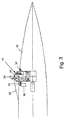
- Figs. 3 and 4 illustrate a cooling system for a single sensing unit, as that of Fig. 1, but it is clear that the same cooling system can be used for both sensing units, when two are present as in Fig. 2.
- the missile and the sensing unit are indicated by the same numerals as in Fig. 1.
- a motor 30 and a gearing 31 are provided for rotating dome 14 on supports 32.
- a cowling 33 leads a cooling fluid from a reservoir, not shown, to the dome. The cooling fluid is discharged as indicated by the arrows 34. Because the dome rotates, all its surface is successively exposed to the cooling gas and cooled.
- Fig. 6 shows the same apparatus as in Fig. 1, with the addition of conformed antenna strips 42.
- antennae could be mounted in missiles provided with two sensing units, as in Fig. 2.
Landscapes
- Engineering & Computer Science (AREA)
- General Engineering & Computer Science (AREA)
- Chemical & Material Sciences (AREA)
- Combustion & Propulsion (AREA)
- Physics & Mathematics (AREA)
- Electromagnetism (AREA)
- Aiming, Guidance, Guns With A Light Source, Armor, Camouflage, And Targets (AREA)
- Radar Systems Or Details Thereof (AREA)
Applications Claiming Priority (2)
| Application Number | Priority Date | Filing Date | Title |
|---|---|---|---|
| IL13418900A IL134189A0 (en) | 2000-01-24 | 2000-01-24 | Device |
| IL13418900 | 2000-01-24 |
Publications (2)
| Publication Number | Publication Date |
|---|---|
| EP1120624A2 true EP1120624A2 (de) | 2001-08-01 |
| EP1120624A3 EP1120624A3 (de) | 2001-10-10 |
Family
ID=11073742
Family Applications (1)
| Application Number | Title | Priority Date | Filing Date |
|---|---|---|---|
| EP01200262A Withdrawn EP1120624A3 (de) | 2000-01-24 | 2001-01-23 | Flugkörperverfolgungsvorrichtung |
Country Status (3)
| Country | Link |
|---|---|
| US (1) | US20010013565A1 (de) |
| EP (1) | EP1120624A3 (de) |
| IL (1) | IL134189A0 (de) |
Cited By (2)
| Publication number | Priority date | Publication date | Assignee | Title |
|---|---|---|---|---|
| EP1340957A3 (de) * | 2002-02-28 | 2005-01-19 | Rafael - Armament Development Authority Ltd. | Verfahren und Vorrichtung zur Vorbeugung einer Kardanabriegelung |
| WO2006038215A1 (en) * | 2004-10-05 | 2006-04-13 | Israel Aerospace Industries Ltd. | Kill payload of a weapon |
Families Citing this family (11)
| Publication number | Priority date | Publication date | Assignee | Title |
|---|---|---|---|---|
| US6331166B1 (en) * | 1998-03-03 | 2001-12-18 | Senorx, Inc. | Breast biopsy system and method |
| US7145734B2 (en) * | 2004-08-03 | 2006-12-05 | Raytheon Company | Windowed optical system having a tilted optical element to correct aberrations |
| US7236299B1 (en) | 2006-04-11 | 2007-06-26 | Bae Systems Information And Electronic Systems Integration Inc. | Compact periscopic beam director |
| DE102009029895B4 (de) * | 2009-06-23 | 2018-01-25 | Diehl Defence Gmbh & Co. Kg | Optisches System für einen Flugkörper und Verfahren zum Abbilden eines Gegenstands |
| US8575527B2 (en) * | 2010-11-10 | 2013-11-05 | Lockheed Martin Corporation | Vehicle having side portholes and an array of fixed EO imaging sub-systems utilizing the portholes |
| WO2014035525A2 (en) * | 2012-06-12 | 2014-03-06 | Integral Laser Solutions, Llc. | Active cooling of high speed seeker missile domes and radomes |
| US10345087B2 (en) * | 2017-08-01 | 2019-07-09 | BAE Systems Informaticn and Electronic Systems Integration Inc. | Mid body seeker payload |
| FR3090896B1 (fr) * | 2018-12-20 | 2021-03-05 | Safran Electronics & Defense | Dispositif de detection optique d’un engin volant autoguide |
| US11371806B2 (en) * | 2019-08-05 | 2022-06-28 | Bae Systems Information And Electronic Systems Integration Inc. | Midbody camera/sensor navigation and automatic target recognition |
| DE102020001153C5 (de) * | 2020-02-21 | 2026-03-26 | Diehl Defence Gmbh & Co. Kg | Flugkörper, insbesondere Lenkflugkörper, mit einer Radarsensoreinheit |
| US12669308B2 (en) * | 2023-10-11 | 2026-06-30 | The Boeing Company | Target tracking apparatus and associated systems methods |
Citations (2)
| Publication number | Priority date | Publication date | Assignee | Title |
|---|---|---|---|---|
| US3974985A (en) | 1972-05-18 | 1976-08-17 | The United States Of America As Represented By The Secretary Of The Navy | Wide angle seeker |
| GB2284465A (en) | 1993-12-01 | 1995-06-07 | Israel State | Missile |
Family Cites Families (1)
| Publication number | Priority date | Publication date | Assignee | Title |
|---|---|---|---|---|
| DE4442134A1 (de) * | 1994-11-26 | 1996-05-30 | Bodenseewerk Geraetetech | Lenkschleife für Flugkörper |
-
2000
- 2000-01-24 IL IL13418900A patent/IL134189A0/xx unknown
-
2001
- 2001-01-22 US US09/767,192 patent/US20010013565A1/en not_active Abandoned
- 2001-01-23 EP EP01200262A patent/EP1120624A3/de not_active Withdrawn
Patent Citations (2)
| Publication number | Priority date | Publication date | Assignee | Title |
|---|---|---|---|---|
| US3974985A (en) | 1972-05-18 | 1976-08-17 | The United States Of America As Represented By The Secretary Of The Navy | Wide angle seeker |
| GB2284465A (en) | 1993-12-01 | 1995-06-07 | Israel State | Missile |
Cited By (3)
| Publication number | Priority date | Publication date | Assignee | Title |
|---|---|---|---|---|
| EP1340957A3 (de) * | 2002-02-28 | 2005-01-19 | Rafael - Armament Development Authority Ltd. | Verfahren und Vorrichtung zur Vorbeugung einer Kardanabriegelung |
| US6853349B1 (en) | 2002-02-28 | 2005-02-08 | Rafael-Armament Development Authority Ltd | Method and device for prevention of gimbal-locking |
| WO2006038215A1 (en) * | 2004-10-05 | 2006-04-13 | Israel Aerospace Industries Ltd. | Kill payload of a weapon |
Also Published As
| Publication number | Publication date |
|---|---|
| US20010013565A1 (en) | 2001-08-16 |
| EP1120624A3 (de) | 2001-10-10 |
| IL134189A0 (en) | 2001-04-30 |
Similar Documents
| Publication | Publication Date | Title |
|---|---|---|
| US9188481B2 (en) | Sensing/emitting apparatus, system and method | |
| US20010013565A1 (en) | Missile tracking device | |
| US8049869B2 (en) | Dual FOV imaging semi-active laser system | |
| US5796474A (en) | Projectile tracking system | |
| US4087061A (en) | Wide angle seeker | |
| JP3148724B2 (ja) | 背景減算機能を備えた共用アパーチャ・ダイクロイック・アクティブ追跡機 | |
| US8284382B2 (en) | Lookdown and loitering LADAR system | |
| EP1357398B1 (de) | Optisches System mit kombiniertem Laser/FLIR | |
| CA2243685C (en) | Target-tracking laser designator | |
| US20090260511A1 (en) | Target acquisition and tracking system | |
| CA2243753C (en) | Dichroic active tracker | |
| US8354626B2 (en) | Optical system for a missile, and method for imaging an object | |
| EP2442131A1 (de) | Verteiltes Störsendersystem | |
| US5418364A (en) | Optically multiplexed dual line of sight flir system | |
| US5529261A (en) | Missile | |
| US5918305A (en) | Imaging self-referencing tracker and associated methodology | |
| CA3238614A1 (en) | An aerial camera system | |
| JPH02115784A (ja) | 監視センサ | |
| US5669580A (en) | Sensor device for a missile | |
| US6484619B1 (en) | Observation or sighting system | |
| US5681009A (en) | Missile having endoatmospheric and exoatmospheric seeker capability | |
| US3974985A (en) | Wide angle seeker | |
| US6533218B1 (en) | Reconnaissance pod with movable sensor-bay window | |
| US6552318B1 (en) | Sensor system with rigid-body error correcting element | |
| US4886330A (en) | Infra red imaging system |
Legal Events
| Date | Code | Title | Description |
|---|---|---|---|
| PUAI | Public reference made under article 153(3) epc to a published international application that has entered the european phase |
Free format text: ORIGINAL CODE: 0009012 |
|
| AK | Designated contracting states |
Kind code of ref document: A2 Designated state(s): AT BE CH CY DE DK ES FI FR GB GR IE IT LI LU MC NL PT SE TR |
|
| AX | Request for extension of the european patent |
Free format text: AL;LT;LV;MK;RO;SI |
|
| PUAL | Search report despatched |
Free format text: ORIGINAL CODE: 0009013 |
|
| AK | Designated contracting states |
Kind code of ref document: A3 Designated state(s): AT BE CH CY DE DK ES FI FR GB GR IE IT LI LU MC NL PT SE TR |
|
| AX | Request for extension of the european patent |
Free format text: AL;LT;LV;MK;RO;SI |
|
| AKX | Designation fees paid | ||
| REG | Reference to a national code |
Ref country code: DE Ref legal event code: 8566 |
|
| STAA | Information on the status of an ep patent application or granted ep patent |
Free format text: STATUS: THE APPLICATION IS DEEMED TO BE WITHDRAWN |
|
| 18D | Application deemed to be withdrawn |
Effective date: 20020411 |