EP1120693A2 - Dispositif et procédé de formation d'images - Google Patents
Dispositif et procédé de formation d'images Download PDFInfo
- Publication number
- EP1120693A2 EP1120693A2 EP01100979A EP01100979A EP1120693A2 EP 1120693 A2 EP1120693 A2 EP 1120693A2 EP 01100979 A EP01100979 A EP 01100979A EP 01100979 A EP01100979 A EP 01100979A EP 1120693 A2 EP1120693 A2 EP 1120693A2
- Authority
- EP
- European Patent Office
- Prior art keywords
- image forming
- forming apparatus
- transfer bias
- voltage
- recited
- Prior art date
- Legal status (The legal status is an assumption and is not a legal conclusion. Google has not performed a legal analysis and makes no representation as to the accuracy of the status listed.)
- Withdrawn
Links
- 238000000034 method Methods 0.000 title claims description 12
- 238000012546 transfer Methods 0.000 claims abstract description 108
- 238000012360 testing method Methods 0.000 claims description 19
- 230000007246 mechanism Effects 0.000 claims description 5
- 238000004140 cleaning Methods 0.000 description 5
- 230000007423 decrease Effects 0.000 description 3
- 230000006870 function Effects 0.000 description 3
- 239000002245 particle Substances 0.000 description 3
- CBENFWSGALASAD-UHFFFAOYSA-N Ozone Chemical compound [O-][O+]=O CBENFWSGALASAD-UHFFFAOYSA-N 0.000 description 2
- 238000007599 discharging Methods 0.000 description 2
- 239000000853 adhesive Substances 0.000 description 1
- 230000001070 adhesive effect Effects 0.000 description 1
- 230000015572 biosynthetic process Effects 0.000 description 1
- 238000011109 contamination Methods 0.000 description 1
- 230000003247 decreasing effect Effects 0.000 description 1
- 238000011161 development Methods 0.000 description 1
- 238000010586 diagram Methods 0.000 description 1
- 230000000694 effects Effects 0.000 description 1
- 230000008030 elimination Effects 0.000 description 1
- 238000003379 elimination reaction Methods 0.000 description 1
- 238000012545 processing Methods 0.000 description 1
- 230000035939 shock Effects 0.000 description 1
- 238000003756 stirring Methods 0.000 description 1
Images


Classifications
-
- G—PHYSICS
- G03—PHOTOGRAPHY; CINEMATOGRAPHY; ANALOGOUS TECHNIQUES USING WAVES OTHER THAN OPTICAL WAVES; ELECTROGRAPHY; HOLOGRAPHY
- G03G—ELECTROGRAPHY; ELECTROPHOTOGRAPHY; MAGNETOGRAPHY
- G03G15/00—Apparatus for electrographic processes using a charge pattern
- G03G15/14—Apparatus for electrographic processes using a charge pattern for transferring a pattern to a second base
- G03G15/16—Apparatus for electrographic processes using a charge pattern for transferring a pattern to a second base of a toner pattern, e.g. a powder pattern, e.g. magnetic transfer
- G03G15/1665—Apparatus for electrographic processes using a charge pattern for transferring a pattern to a second base of a toner pattern, e.g. a powder pattern, e.g. magnetic transfer by introducing the second base in the nip formed by the recording member and at least one transfer member, e.g. in combination with bias or heat
- G03G15/167—Apparatus for electrographic processes using a charge pattern for transferring a pattern to a second base of a toner pattern, e.g. a powder pattern, e.g. magnetic transfer by introducing the second base in the nip formed by the recording member and at least one transfer member, e.g. in combination with bias or heat at least one of the recording member or the transfer member being rotatable during the transfer
- G03G15/1675—Apparatus for electrographic processes using a charge pattern for transferring a pattern to a second base of a toner pattern, e.g. a powder pattern, e.g. magnetic transfer by introducing the second base in the nip formed by the recording member and at least one transfer member, e.g. in combination with bias or heat at least one of the recording member or the transfer member being rotatable during the transfer with means for controlling the bias applied in the transfer nip
-
- G—PHYSICS
- G03—PHOTOGRAPHY; CINEMATOGRAPHY; ANALOGOUS TECHNIQUES USING WAVES OTHER THAN OPTICAL WAVES; ELECTROGRAPHY; HOLOGRAPHY
- G03G—ELECTROGRAPHY; ELECTROPHOTOGRAPHY; MAGNETOGRAPHY
- G03G2215/00—Apparatus for electrophotographic processes
- G03G2215/16—Transferring device, details
- G03G2215/1604—Main transfer electrode
- G03G2215/1614—Transfer roll
Definitions
- the present invention relates to an apparatus for applying a voltage to a transfer roller for the purpose of transferring a toner image formed on a photosensitive body of an image forming apparatus onto a recording sheet, and especially to an apparatus equipped with a control means that applies a test voltage to the transfer roller and programs (decides and adjusts) the transfer bias.
- the present invention also relates to an image forming method employing said apparatus.
- a toner image is transferred to a recording sheet as follows: an electrostatic latent image is formed on a photosensitive body (drum) by means of an exposing unit, and visualized with a toner supplied from a developer unit. The visualized image is a toner image, which is then transferred to the recording sheet. Finally the recording sheet bearing the toner image is fixed through a fixing unit to be a copy.
- a discharging member such as a corotron or a contact-transfer member such as a transfer roller may be used in order to transfer the image from the photosensitive body.
- One of the advantages of using a contact-transfer member such as a transfer roller over the corotron is that there is no ozone generated since unlike the corotron no corona discharge occurs. This results in elimination of such means as an ozone disposal unit in the exhaust system of an image forming apparatus.
- the voltage application to said transfer roller as the transfer bias is greatly influenced by the temperature within the apparatus and also in the area surrounding it. At a low temperature, a voltage of a relatively large value should be applied (not larger than 3.5kV), and the voltage decreases as the temperature within the apparatus increases and is set within the range between 0.5 and 2kV.
- a test voltage is applied to set the bias during the initializing procedure of the image forming apparatus. Later, after a predetermined number of sheets are recorded, a feed back sequence (hereinafter FB sequence) to apply a test voltage again is performed to change the setting of the transfer bias voltage.
- an image forming apparatus provided with a transfer roller and performing a sequence during jobs in order to decide a value of the transfer bias by applying a test voltage, characterized in that whenever the saturation is reached by the voltage to be applied, which is decided based on the detected currents obtained when the test voltage is applied, said FB sequence will no longer be performed at least during the job.
- the detected current at the time of the application of the test voltage exceeds a certain level, it may be considered that the saturation has been reached.
- the transfer bias may be determined based on the detected current when the test voltage is applied, and also on the temperature at that moment.
- the time required until completion of the job is shortened because wasteful sequences are omitted after it is decided that the saturation has been reached by the transfer voltage that is determined based on the current detected upon application of the test voltage in the FB sequence. Furthermore, by deciding and/or adjusting said transfer bias based on the conditions including both the detected current and temperature in said FB sequence, it is possible to more accurately decide and adjust the transfer bias in view of the environment. Moreover, users have to wait less because the time required for the printing in large number is reduced. Further, the decreased time of operation for each component member of the image forming apparatus means the increased life of the processing units.
- a photosensitive unit 20 and a developer unit 10 in an image forming apparatus illustrated are a photosensitive unit 20 and a developer unit 10 in an image forming apparatus.
- a photosensitive drum 22 is located in the photosensitive unit 20 in a way such that a development section of the photosensitive drum 22 is located opposite to a developing roller 14 of the developer unit 10.
- a toner contained in a toner container 11 is agitated by an agitator 12 as it is fed toward a feed roller 13. After passing by the feed roller 13, the toner is negatively charged between the feed roller 13 and the developing roller 14, both of which rotate in the direction of the arrow X, and at the same time the toner is adhered to the developing roller 14 in a thin layer.
- the toner is adhered to the surface of the developing roller 14, it is formed as an even, thin layer by means of a blade member 15, then exposed at a position where the photosensitive drum 22 is located at the opposite side, and adhered to an electrostatic latent image at a position where the toner touches the photosensitive drum 22, which rotates in the direction of the arrow X'.
- the photosensitive unit 20, which is located side by side with the developer unit 10, includes the photosensitive drum 22 used as a photosensitive body, which is rotated at a predetermined rate driven by a driving mechanism (not shown) mounted on a frame 21, and a transfer roller 26, which is used to transfer the toner image formed on the photosensitive drum 22 onto recording sheets. Further, around the photosensitive drum 22 are positioned the transfer roller 26, a memory removing member 23, a charging roller 24, and an exposing unit 25 in the rotational order of the photosensitive drum 22. After the photosensitive drum 22 is uniformly charged by the charging roller 24, an electrostatic latent image is formed on the surface of the photosensitive drum 22 with a light beam emitted from the exposing unit 25. On the electrostatic latent image is placed the toner from the developing roller 14 to create a toner image, which will be transferred to a recording sheet being fed to the image transfer section by applying a predetermined transfer voltage from the back of the recording sheet by means of the transfer roller 26,
- the image forming apparatus described and illustrated here is what is called a cleaner-less apparatus, in which cleaning means are not used to remove the residual toner and other things on the photosensitive drum after the toner image is transferred on a recording sheet. Instead, after the memory erasing member 23 and the charging member 24 reduce adhesive strength of the toner, the toner is recollected by the developing roller 14 into the developer unit 10 to be re-used mixed with newly supplied toner.
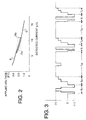
- the transfer bias is controlled based on the relationship between the applied voltage (kV) and the detected current ( ⁇ A) as shown in the graph of Fig. 2, indicated in the vertical axis and in the horizontal axis respectively.
- the voltage to be applied is controlled in accordance with the curve B.
- the voltage to be applied is controlled in accordance with the curve C.
- the curves have been changed to Ba and Ca to control the voltage application. It should be noted that the curves Ba and Ca are actually overlapped completely, but the two curves are described separately for the convenience of explanation.
- a cleaning sequence is employed for the transfer roller 26, whereby the toner, negatively charged, attaching to the transfer roller 26 as well as paper particles and others can be transferred back to the photosensitive drum 22 whenever a predetermined number of recorded sheets are made, and every time the recording (printing) onto a recording sheet is started.
- the control of the voltage applied to the transfer roller 26 is performed in a way shown in the time chart of Fig. 3.
- test voltage application is performed against the transfer roller for a predetermined duration of T3.
- the initializing operation is performed to the elements and functions of the apparatus.
- the voltage is within the range between the cleaning voltage (negative) and the transfer voltage (positive).
- the initial amount of voltage to be applied to the transfer roller is decided.
- the operations of the image forming mechanism and paper feed mechanism are started, and then the operation of transferring the toner image from the photosensitive drum 22 to the recording sheets to produce a predetermined number of recorded sheets begins.
- the recording on the recording sheets is performed based on the set number displayed on the control panel of the image forming apparatus.
- FB sequence is also programmed to be performed after a certain number of recording sheets are recorded.
- the duration of successively feeding a predetermined number of recording sheets is indicated by Ta
- the duration of the FB sequence is indicated by T1.
- the transfer voltage positive
- the transfer voltage is maintained at the same level, though the voltage is reduced to a level of pre-transfer voltage at a position of a gap between the two recording sheets successively fed through the recording sheet passage.
- the operations of feeding recording sheets and the forming of toner image on the photosensitive drum are stopped, and the FB sequence for the transfer roller is performed.
- the operation of recording on recording sheets is stopped.
- the timing of beginning the FB sequence is programmed in advance in the operation program in the main control unit of the image forming apparatus. After a certain number of recorded sheets are made (Ta), the FB is performed. The currents detected when the test voltage is applied will determine the next voltage to be applied. Each time the FB sequence is completed, the value of voltage to be applied is adjusted.
- the advantage of performing the FB sequences is that the voltage to be applied for the transfer roller can be changed in accordance with the curves B, C (of the control factors) shown in Fig. 2.
- the horizontal axis indicates time and the vertical axis indicates voltage to be applied.
- the transfer voltage (positive) is determined in accordance with the current-voltage relationship shown in Fig. 2 based on the detected currents.
- the voltage of -900V is once applied to the transfer roller, and then the transfer voltage (positive) is applied for a predetermined duration. Subsequently, the voltage is increased from 0V to the transfer voltage (positive) in the stepwise manner.
- the transfer voltage is generally maintained.
- the predetermined number if indicated in terms of time, after the duration of Ta
- another FB sequence begins, and the next value for the voltage to be applied to the transfer roller is decided. Therefore, in an example shown in Fig. 3, as the number of recorded sheets increases, the detected current changes. As a result, the transfer voltage applied to the transfer roller can be reduced accordingly.
- the graph of Fig. 4 shows the data obtained in one type of image forming apparatus.
- the temperature inside the apparatus increases, but also the environment of the area surrounding the photosensitive drum changes.
- the curves B, Ba (Ca), C in Fig. 2 the value of the voltage to be applied compared to the detected current decreases.
- the currents detected along with the changing environment decreases gradually.
- the bias voltage to be applied after the FB sequence is decided based on the detected current and the value of voltage to be applied determined from in Fig 4.
- ⁇ for example, +500V
- programming +500V is enough for appropriate transfer of the toner image from the photosensitive drum to the recording sheet.
- this stage where the transfer bias voltage becomes ⁇ is called the saturation.
- the saturation Once the saturation has been reached, even if the FB sequence is performed thereafter, the value of the bias voltage is not changed. In other words, this value is the lowest. Therefore, once the voltage has reached the lowest bias voltage, there will be no need to perform FB sequences. So, for example, once the detected current reaches 25 ⁇ A, FB sequence can be omitted, and successive recording operation without interruption is made possible.
- a transfer voltage control unit 30 is connected for the transfer roller 26 as is shown in Fig. 1 to apply the programmed value of voltage to the axis of the transfer roller 26.
- the transfer voltage control unit 30 includes a voltage application circuit 32 that applies voltage to the transfer roller under control of a control circuit 31, a memory 33 that stores the current-voltage relationships as shown in Figs. 2 and 4 for the control circuit 31, and a control table 34 that is used for changing the control conditions based on the detected current.
- a sensor circuit 36 which detects a current obtained from the transfer roller when test voltages are applied in FB sequences is connected to the control circuit 31. Based on the information from the current detecting circuit 36, the voltage applied to the transfer roller after a FB sequence is programmed. Further, another sensor 35 is installed to measure the temperature at a certain position inside the image forming apparatus. The temperature information detected by the sensor 35 is input into the control circuit 31 so that transfer voltages can be adjusted whenever necessary in accordance with the temperatures within the apparatus.
- the transfer voltage control unit 30 When it is determined that a certain number of copied sheets are made based on the conditions set in the main control unit of the image forming apparatus, the transfer voltage control unit 30 performs the FB sequence. During the FB sequence, the paper feed is stopped, and voltage application to the voltage application units for the photosensitive drum 22 including the charging roller 24 and the developing roller 14 is suspended. Subsequently, -900v is applied to the transfer roller and then a test voltage (positive) is applied so that the current can be detected. After the test voltage is applied, the voltage is returned to 0V, and then the voltage is increased to the level decided based on the detected current in several increments so that the electrical shock to the photosensitive drum will be alleviated.
- a test voltage positive
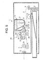
- the arrangement for and method of changing the voltage applied to the transfer roller26 described above may be incorporated in an image forming apparatus 1 shown in Fig.5.
- the image forming apparatus 1 can be combined with an image scanning apparatus to create an electro-photographic copy machine, or with a personal computer interface to create a printer, or with an image scanning apparatus as well as a facsimile module to create a facsimile machine, or a multi-purpose machine where several functions are combined.
- a pick-up roller 3 located in the feed section of a feed tray 2 sends recording sheets one by one.
- Paper feed roller mechanisms 4 and 6 send the recording sheets through a paper feed passage 5. While the recording sheet goes between a photosensitive drum 22 and a transfer roller 26, a toner image formed on the photosensitive drum 22 is transferred.
- the recording sheet on which the toner image is transferred goes on between a heat roller 7a and a nip roller 7b of a fixing unit 7 to be fixed and then discharged to a unloading tray (not shown) by means of a discharging roller 8.
- the information supplied to an exposure member 25 may be supplied from an image scanner (not shown) which is used in combination with the image forming apparatus 1, or from digital signals received on a facsimile machine.
- the formation of image on the photosensitive body is done through light emitted from LED elements of the exposure member 25. It should be noted that similar reference numerals are used in Figs. 1 and 5 to designate similar elements.
Landscapes
- Physics & Mathematics (AREA)
- General Physics & Mathematics (AREA)
- Electrostatic Charge, Transfer And Separation In Electrography (AREA)
- Control Or Security For Electrophotography (AREA)
- Handling Of Sheets (AREA)
Applications Claiming Priority (2)
| Application Number | Priority Date | Filing Date | Title |
|---|---|---|---|
| JP2000016479A JP2001209261A (ja) | 2000-01-26 | 2000-01-26 | 画像形成装置 |
| JP2000016479 | 2000-01-26 |
Publications (2)
| Publication Number | Publication Date |
|---|---|
| EP1120693A2 true EP1120693A2 (fr) | 2001-08-01 |
| EP1120693A3 EP1120693A3 (fr) | 2006-11-02 |
Family
ID=18543608
Family Applications (1)
| Application Number | Title | Priority Date | Filing Date |
|---|---|---|---|
| EP01100979A Withdrawn EP1120693A3 (fr) | 2000-01-26 | 2001-01-17 | Dispositif et procédé de formation d'images |
Country Status (3)
| Country | Link |
|---|---|
| US (1) | US6381425B2 (fr) |
| EP (1) | EP1120693A3 (fr) |
| JP (1) | JP2001209261A (fr) |
Families Citing this family (9)
| Publication number | Priority date | Publication date | Assignee | Title |
|---|---|---|---|---|
| US6781880B2 (en) * | 2002-07-19 | 2004-08-24 | Micron Technology, Inc. | Non-volatile memory erase circuitry |
| JP3833181B2 (ja) * | 2003-02-25 | 2006-10-11 | キヤノン株式会社 | 転写装置 |
| JP4383807B2 (ja) * | 2003-08-29 | 2009-12-16 | キヤノン株式会社 | 画像形成装置 |
| US7319829B2 (en) * | 2005-08-26 | 2008-01-15 | Lexmark International, Inc. | Transfer bias adjustment based on component life |
| US7539431B2 (en) * | 2006-06-29 | 2009-05-26 | Kabushiki Kaisha Toshiba | Image forming apparatus and techniques for collecting toner |
| US20080145080A1 (en) * | 2006-12-14 | 2008-06-19 | William Paul Cook | Inter-Page Belt Impedance Measurement |
| US8036547B2 (en) * | 2008-09-29 | 2011-10-11 | Lexmark International, Inc. | Method for adjusting transfer voltage controls based on environmental conditions to improve print quality in a direct transfer image forming device |
| US8483585B2 (en) * | 2008-09-29 | 2013-07-09 | Lexmark International, Inc. | System and method for adjusting voltage bias of a charge roller of an image forming device based on environmental conditions to control white vector |
| US8213817B2 (en) * | 2008-09-29 | 2012-07-03 | Lexmark International, Inc. | Transfer print voltage adjustment based on temperature, humidity, and transfer feedback voltage |
Family Cites Families (9)
| Publication number | Priority date | Publication date | Assignee | Title |
|---|---|---|---|---|
| JPH08137355A (ja) * | 1994-11-08 | 1996-05-31 | Minolta Co Ltd | 画像形成装置 |
| JP3568142B2 (ja) * | 1996-08-06 | 2004-09-22 | 株式会社リコー | 画像形成装置 |
| JPH10186898A (ja) * | 1996-12-27 | 1998-07-14 | Murata Mach Ltd | 画像記録装置 |
| JPH10186899A (ja) * | 1996-12-27 | 1998-07-14 | Murata Mach Ltd | 画像記録装置 |
| JP3839933B2 (ja) * | 1997-09-22 | 2006-11-01 | キヤノン株式会社 | 画像形成装置 |
| JPH11223968A (ja) | 1998-02-05 | 1999-08-17 | Fuji Xerox Co Ltd | 画像形成装置 |
| JPH11305565A (ja) | 1998-04-27 | 1999-11-05 | Murata Mach Ltd | 画像形成装置 |
| DE69914399T2 (de) * | 1998-04-20 | 2004-11-11 | Murata Kikai K.K. | Bilderzeugungsgerät |
| JPH11305569A (ja) * | 1998-04-27 | 1999-11-05 | Murata Mach Ltd | 画像形成装置 |
-
2000
- 2000-01-26 JP JP2000016479A patent/JP2001209261A/ja active Pending
-
2001
- 2001-01-17 EP EP01100979A patent/EP1120693A3/fr not_active Withdrawn
- 2001-01-24 US US09/768,701 patent/US6381425B2/en not_active Expired - Fee Related
Non-Patent Citations (1)
| Title |
|---|
| None * |
Also Published As
| Publication number | Publication date |
|---|---|
| US6381425B2 (en) | 2002-04-30 |
| US20010009616A1 (en) | 2001-07-26 |
| EP1120693A3 (fr) | 2006-11-02 |
| JP2001209261A (ja) | 2001-08-03 |
Similar Documents
| Publication | Publication Date | Title |
|---|---|---|
| EP0973073A2 (fr) | Appareil de formation d'images | |
| US7805089B2 (en) | Image forming apparatus | |
| US6381425B2 (en) | Image forming apparatus and image forming method employing the same | |
| CN1139224A (zh) | 图像形成装置 | |
| US5978616A (en) | Contact charger of an electrophotographic image forming apparatus | |
| JP2000231317A (ja) | 画像形成装置 | |
| US11656559B2 (en) | Image forming apparatus that stops voltage application to a charger based on a current flowing through an image carrier motor after execution of stop control | |
| JP3553817B2 (ja) | 画像形成装置 | |
| US6370345B2 (en) | Image forming apparatus and image forming method employing the same | |
| JPH07244420A (ja) | 画像形成装置 | |
| JP5097602B2 (ja) | 画像形成装置 | |
| JP2009025348A (ja) | 画像形成装置 | |
| JPH09127767A (ja) | 帯電装置 | |
| JP2004037751A (ja) | 画像形成装置 | |
| JP4194177B2 (ja) | 画像形成装置 | |
| JP3553824B2 (ja) | 画像形成装置 | |
| JP4147798B2 (ja) | 画像形成装置 | |
| JP2010014995A (ja) | 画像形成装置 | |
| KR100517511B1 (ko) | 전자사진 형성장치의 대전롤러의 저항 감지방법 및 장치 | |
| JP3406754B2 (ja) | 画像形成装置 | |
| JP2018132605A (ja) | 画像形成装置 | |
| JP2024010631A (ja) | 画像形成装置 | |
| JPH08220956A (ja) | 画像形成装置 | |
| JPH0667518A (ja) | 現像バイアス制御装置 | |
| JPH117207A (ja) | 画像形成装置 |
Legal Events
| Date | Code | Title | Description |
|---|---|---|---|
| PUAI | Public reference made under article 153(3) epc to a published international application that has entered the european phase |
Free format text: ORIGINAL CODE: 0009012 |
|
| AK | Designated contracting states |
Kind code of ref document: A2 Designated state(s): AT BE CH CY DE DK ES FI FR GB GR IE IT LI LU MC NL PT SE TR |
|
| AX | Request for extension of the european patent |
Free format text: AL;LT;LV;MK;RO;SI |
|
| PUAL | Search report despatched |
Free format text: ORIGINAL CODE: 0009013 |
|
| AK | Designated contracting states |
Kind code of ref document: A3 Designated state(s): AT BE CH CY DE DK ES FI FR GB GR IE IT LI LU MC NL PT SE TR |
|
| AX | Request for extension of the european patent |
Extension state: AL LT LV MK RO SI |
|
| 17P | Request for examination filed |
Effective date: 20061228 |
|
| 17Q | First examination report despatched |
Effective date: 20070227 |
|
| AKX | Designation fees paid |
Designated state(s): DE FR GB |
|
| STAA | Information on the status of an ep patent application or granted ep patent |
Free format text: STATUS: THE APPLICATION HAS BEEN WITHDRAWN |
|
| 18W | Application withdrawn |
Effective date: 20091207 |