EP1120859A2 - Reihenklemme mit Schneid-Anschlussvorrichtung - Google Patents
Reihenklemme mit Schneid-Anschlussvorrichtung Download PDFInfo
- Publication number
- EP1120859A2 EP1120859A2 EP01100853A EP01100853A EP1120859A2 EP 1120859 A2 EP1120859 A2 EP 1120859A2 EP 01100853 A EP01100853 A EP 01100853A EP 01100853 A EP01100853 A EP 01100853A EP 1120859 A2 EP1120859 A2 EP 1120859A2
- Authority
- EP
- European Patent Office
- Prior art keywords
- terminal
- terminal housing
- conductor
- block according
- terminal block
- Prior art date
- Legal status (The legal status is an assumption and is not a legal conclusion. Google has not performed a legal analysis and makes no representation as to the accuracy of the status listed.)
- Withdrawn
Links
- 238000009413 insulation Methods 0.000 title claims abstract description 16
- 238000006073 displacement reaction Methods 0.000 title 1
- 238000003780 insertion Methods 0.000 claims description 48
- 230000037431 insertion Effects 0.000 claims description 48
- 239000004020 conductor Substances 0.000 claims description 45
- 239000000463 material Substances 0.000 claims description 10
- 229910000831 Steel Inorganic materials 0.000 claims description 7
- 239000010959 steel Substances 0.000 claims description 7
- RYGMFSIKBFXOCR-UHFFFAOYSA-N Copper Chemical compound [Cu] RYGMFSIKBFXOCR-UHFFFAOYSA-N 0.000 description 3
- 229910052802 copper Inorganic materials 0.000 description 3
- 239000010949 copper Substances 0.000 description 3
- 238000004519 manufacturing process Methods 0.000 description 2
- 239000002184 metal Substances 0.000 description 2
- 229910052751 metal Inorganic materials 0.000 description 2
- 238000001746 injection moulding Methods 0.000 description 1
- 238000009434 installation Methods 0.000 description 1
- 230000000149 penetrating effect Effects 0.000 description 1
- 238000000926 separation method Methods 0.000 description 1
Images

Classifications
-
- H—ELECTRICITY
- H01—ELECTRIC ELEMENTS
- H01R—ELECTRICALLY-CONDUCTIVE CONNECTIONS; STRUCTURAL ASSOCIATIONS OF A PLURALITY OF MUTUALLY-INSULATED ELECTRICAL CONNECTING ELEMENTS; COUPLING DEVICES; CURRENT COLLECTORS
- H01R4/00—Electrically-conductive connections between two or more conductive members in direct contact, i.e. touching one another; Means for effecting or maintaining such contact; Electrically-conductive connections having two or more spaced connecting locations for conductors and using contact members penetrating insulation
- H01R4/24—Connections using contact members penetrating or cutting insulation or cable strands
- H01R4/2416—Connections using contact members penetrating or cutting insulation or cable strands the contact members having insulation-cutting edges, e.g. of tuning fork type
- H01R4/242—Connections using contact members penetrating or cutting insulation or cable strands the contact members having insulation-cutting edges, e.g. of tuning fork type the contact members being plates having a single slot
- H01R4/2425—Flat plates, e.g. multi-layered flat plates
- H01R4/2429—Flat plates, e.g. multi-layered flat plates mounted in an insulating base
- H01R4/2433—Flat plates, e.g. multi-layered flat plates mounted in an insulating base one part of the base being movable to push the cable into the slot
-
- H—ELECTRICITY
- H01—ELECTRIC ELEMENTS
- H01R—ELECTRICALLY-CONDUCTIVE CONNECTIONS; STRUCTURAL ASSOCIATIONS OF A PLURALITY OF MUTUALLY-INSULATED ELECTRICAL CONNECTING ELEMENTS; COUPLING DEVICES; CURRENT COLLECTORS
- H01R4/00—Electrically-conductive connections between two or more conductive members in direct contact, i.e. touching one another; Means for effecting or maintaining such contact; Electrically-conductive connections having two or more spaced connecting locations for conductors and using contact members penetrating insulation
- H01R4/24—Connections using contact members penetrating or cutting insulation or cable strands
- H01R4/2416—Connections using contact members penetrating or cutting insulation or cable strands the contact members having insulation-cutting edges, e.g. of tuning fork type
- H01R4/242—Connections using contact members penetrating or cutting insulation or cable strands the contact members having insulation-cutting edges, e.g. of tuning fork type the contact members being plates having a single slot
- H01R4/2425—Flat plates, e.g. multi-layered flat plates
- H01R4/2429—Flat plates, e.g. multi-layered flat plates mounted in an insulating base
-
- H—ELECTRICITY
- H01—ELECTRIC ELEMENTS
- H01R—ELECTRICALLY-CONDUCTIVE CONNECTIONS; STRUCTURAL ASSOCIATIONS OF A PLURALITY OF MUTUALLY-INSULATED ELECTRICAL CONNECTING ELEMENTS; COUPLING DEVICES; CURRENT COLLECTORS
- H01R9/00—Structural associations of a plurality of mutually-insulated electrical connecting elements, e.g. terminal strips or terminal blocks; Terminals or binding posts mounted upon a base or in a case; Bases therefor
- H01R9/22—Bases, e.g. strip, block, panel
- H01R9/24—Terminal blocks
- H01R9/26—Clip-on terminal blocks for side-by-side rail- or strip-mounting
-
- H—ELECTRICITY
- H01—ELECTRIC ELEMENTS
- H01R—ELECTRICALLY-CONDUCTIVE CONNECTIONS; STRUCTURAL ASSOCIATIONS OF A PLURALITY OF MUTUALLY-INSULATED ELECTRICAL CONNECTING ELEMENTS; COUPLING DEVICES; CURRENT COLLECTORS
- H01R9/00—Structural associations of a plurality of mutually-insulated electrical connecting elements, e.g. terminal strips or terminal blocks; Terminals or binding posts mounted upon a base or in a case; Bases therefor
- H01R9/22—Bases, e.g. strip, block, panel
- H01R9/24—Terminal blocks
- H01R9/26—Clip-on terminal blocks for side-by-side rail- or strip-mounting
- H01R9/2616—End clamping members
Definitions
- the invention relates to a terminal block according to the preamble of claim 1.
- a generic terminal block with a penetrating conductor insulation Connection device is known from DE 196 27 209.
- the one shown in this document Connection device has contact cutting with cutting edges that are expand to contact areas.
- the contact surfaces enable a Large-area contacting of the line wire of the connected electrical conductor than the actual contact cutting for cutting the conductor, which the Touch the conductor essentially "line-like".
- the terminal housing is arranged in the terminal housing and / or in one piece with the Terminal housing designed insertion element for inserting the into the terminal housing introduced into the contact cutting edge and / or the contacting area provided and the terminal housing preferably has openings which are dimensioned such that an actuating tool on each side of each conductor how a screwdriver can be guided into the terminal housing, such that by pivoting and / or shifting the actuating tool of the ladder with the insertion element from one side into the contact blade and / or the contact area is feasible and detachable from the other side with or without an insertion element.
- the insertion element is separate, in particular from the metal parts of the connecting element is formed, because in this way a particularly good Guidance of the insertion element in the plastic housing is achieved, in particular, if this is made of plastic, whereby the insertion element compared to the metal parts is isolated.
- At least one side in the terminal housing below at least one of the openings Insertion bevel is provided so that the screwdriver when deriving on the Lead-in chamfer the actuator when switching in the direction of the contact blade presses and / or presses out of the contact blade when switching off.
- the insertion element formed in one piece with the terminal housing preferably enables inserting the conductor inserted into the terminal housing into the Contact cutting edge and / or the contact area.
- the insertion element facilitates in a simple manner the insertion of the conductor into the connection device. If it also made in one piece with the terminal housing (e.g. molded onto this) is, it can also be produced particularly inexpensively. The need for manufacturing a separate insertion element is not required.
- the at least one contact cutting edge is preferably immovable in the terminal housing fixed.
- the insertion element is attached to the Molded molded spring element.
- Spring element one or more pivotable in the terminal housing and to this molded spring bar (s) and a stop for the conductor, which is designed in this way is that by moving the spring element of the conductor at the stop directly in the Contact cutting edge and / or the contacting area is feasible.
- This variant too The invention realizes all the advantages of inexpensive production by injection molding the spring bar (or preferably two parallel spring bars).
- the field element enables a defined, easy mobility of the conductor in the contact cutting edge and can also be used multiple times.
- the spring element Due to the spring element - preferably the spring element has one in the terminal housing pivotable free spring bar with a bulge on which the stop trained for the leader - a leader becomes quasi “automatic” or alone Swiveling the spring bar led into the contact blades.
- the need for a further separate guide element which is separate from the terminal housing - As is known from various other prior art - omitted.
- the insertion element is in contrast as molded insert element molded onto the terminal housing, which via Predetermined breaking points is connected to the terminal housing in such a way that when moving the insertion element in the terminal housing with an operating tool Breakable points can be severed and the conductor can be inserted into the contact blade.
- This variant of the invention can also be produced inexpensively. It is suitable in essential for installation situations in which a multiple actuation of the connection device in all likelihood not necessary since the slider after switching on and off for re-wiring no longer with the terminal housing connected and thus held in its starting position for wiring is.
- the contact blades exist and the contacting areas - in particular as contacting areas designed - from different materials.
- This has the advantage that the material to cut open the insulation - this material should naturally be used the cutting function should be rather hard - as well as the material for contacting - it should good electrical conductivity - can be optimally selected according to your task.
- the conductor was cut open as well also the contacting by a one-piece element. This element is made of steel manufactured, a good cutting function of the insulation can be realized, the contacting but is significantly worse than in the case in which the contact surfaces or areas made of a softer conductive compared to the steel material Material such as copper.
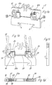
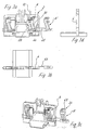
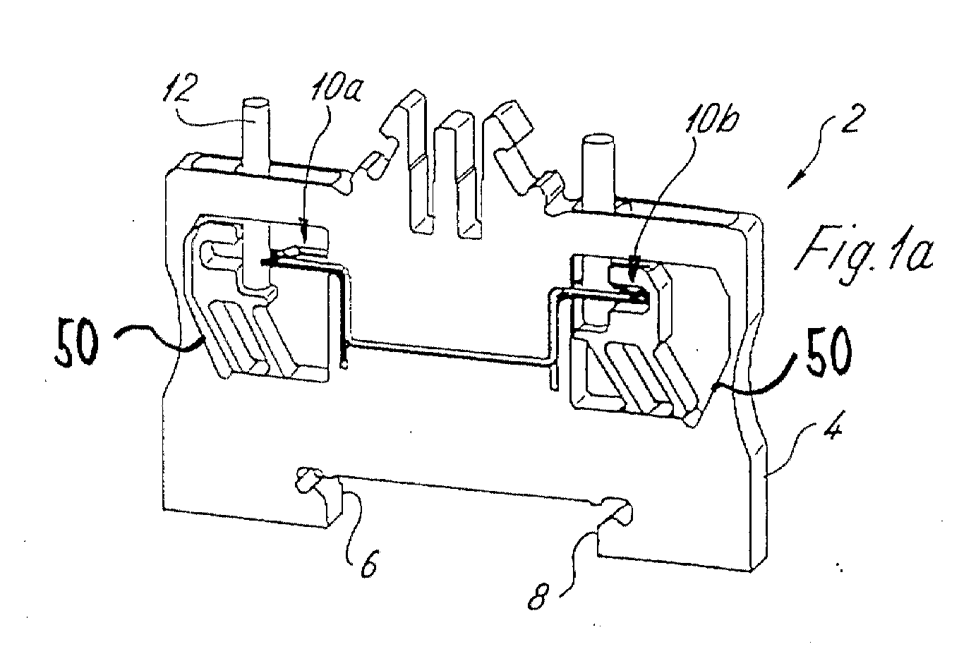
- Fig. 1 shows a terminal block 2 - here a feed-through terminal - with a terminal housing 4 made of plastic, which has locking feet 6 in its lower area in FIG. 8 for snapping the terminal block 2 onto a mounting rail (not shown here) having.
- the terminal housing 4 is with two connection devices 10a, b for one each electrical conductor 12 provided, the conductors 12 each (see FIG. 1d) at least have a line core 14 and an insulation 16 surrounding the line core 14.
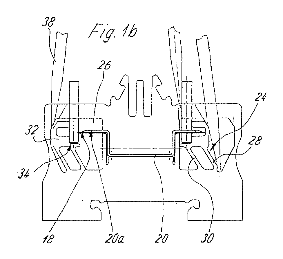
- connection devices 10 each comprise a contact blade 18 - preferably made of sheet steel - for cutting open the insulation 16 of the electrical conductor 12 and a contacting region 20a which is offset longitudinally relative to the contact cutting edge 18 - preferably made of copper - for contacting the at least one line core 14.
- the contact cutting edges 18 of the two connection devices 10a, 10b each sit on the ends of a through busbar 20.
- each connection device 10 is essentially vertical to the direction of insertion of the conductor 12 in the terminal housing 4 and is preferably slotted formed (see Fig. ld), the slot extending to the free end of the contact blade 18 mouth-like widened what the supply of the to be contacted Wire 12 relieved.
- the contact blade 18 made of sheet steel is used only to cut the Insulation 16 of the conductor 12. Slightly offset to the contact edge 18 sets the Busbar 20 on, which in its end region for the contacting area 20a trains the wire 20.
- the busbar 20 is parallel at its ends to the contact cutting edge 18 and is at its end facing the conductor 12 with Expansion bevels 22 provided which the insulation 16 of the conductor, previously from the contact blade 18 has been severed, expand laterally so that the in her End area slotted busbar 20 contact the line wire 14 laterally flat can.
- the busbar 20 has a substantially in the side view of FIG.
- the Contact blade 18 is made of sheet steel to make insulation 16 easy and safe to be able to penetrate, and the busbar 20 is used to ensure a good contact preferably made of copper.
- Two insertion elements 24 are used to insert the conductor 12 into the contact blades.
- these insertion elements 24 comprise two that are open at the top Recess 26 pivotable, mutually parallel spring bars 28, 30, which at their end facing away from the connection area to the rest of the terminal housing 4 are connected to one another via a stepped receptacle 32 Stop 34 for the lower end of the conductor 12 when it is inserted into the terminal housing 4 has.
- the insertion element 24 designed as a spring element can be at an angle of approximately Can be pivoted 20-40 ° in the terminal housing 4, the pivoting of the spring bars 28, 30 through a correspondingly large opening 36 on the top of the terminal housing 4 with the aid of a screwdriver 38. Through the Openings 36 also lead the conductors 12 into the terminal box 4 to the connection devices 10a, 10b out.
- the function of the connecting devices 10a, 10b of this terminal block 2 is like follows: In the relaxed state of the spring bars 28, 30, these lie to the conductor insertion direction slightly inclined. If a conductor 12 from above through the opening 36 in the Guided terminal housing 4, it abuts stop 34. Now becomes the screwdriver 38 on the outside of the conductor 12 and on the outside of the spring element 24 passed into the terminal block, it slides past the spring bars 28, 30. At the The screwdriver 38 slides down and swivels, pushing the insertion or Spring element 24 to the side and presses the lower region of the conductor 12 against the Contact cutting edge 18, where the insulation 16 of the conductor 12 is cut. Another one Swiveling the screwdriver 38 then forces the conductor 12 on the expansion bevels 22 past into the contacting areas 20a (left part of FIG. 1a and 1b).
- FIGS. 1a and 1b illustrates the opening of the connection devices 10a and 10b or the release of the conductor 12 from the connection device 10a, 10b.
- the screwdriver 38 on the (lying on the mounting rail) Passed inside the conductor 12 into the terminal housing 4 (see the left part of FIG. 2) until it rests on the busbar 20.
- the screwdriver 38 By swiveling and / or laterally shift the screwdriver 38 (see the right part of FIG Fig. 1a) to the outside it is possible to remove the conductor 12 from the connection area of the busbar 20 and to press out of the contact blade 18.
- the insertion element 24 is molded onto the terminal housing 4 Insert element formed, which has predetermined breaking points 40, 42 with the terminal housing 4 is connected such that when moving the insertion element in the Recess 26 perpendicular to the direction of the mounting rail in a plane parallel to the mounting rail the predetermined breaking points 40, 42 are severed with the screwdriver 38 and the conductor 12 is inserted into the contact blade.
- the loosening or de-switching takes place analogously to FIG. 1.
- the actuator here has to be seen from two different sides De-energize the terminal. Due to the special training of However, it is basically possible to use a lead-in chamfer, unlike a one-sided one Wiring no additional width for an insertion opening of the operating tool To give away. De-activation can either be done with the help of the insertion element 24 or directly by the action of the screwdriver on the Head 12 take place.
- the insertion elements 24 are designed essentially in the manner of Figure 1. However, they are attached to one another via the parallel spring bars 28, 30 lower pivot element 44, which is pivotable on a film hinge 46 on Terminal housing 4 is mounted such that it is outside from an outer position A ' of the housing can be pivoted into an inner position A in the terminal housing 4.
- connection devices 10 are still with Provide insertion openings 48 for guiding the conductor 12 in a defined manner.
Landscapes
- Connections Arranged To Contact A Plurality Of Conductors (AREA)
Abstract
Description
- Fig. 1a
- eine perspektivische Ansicht einer ersten erfindungsgemäßen Reihenklemme ohne seitliche Gehäuseabdeckung bzw. ohne Gehäusevorderseite zur Veranschaulichung des Be- und Entschaltens der Anschlußvorrichtung; und
- Fig. 1b
- eine erste seitliche Ansicht auf die Reihenklemme der Fig. 1a ohne seitliche Gehäuseabdeckung bzw. ohne Gehäusevorderseite; und
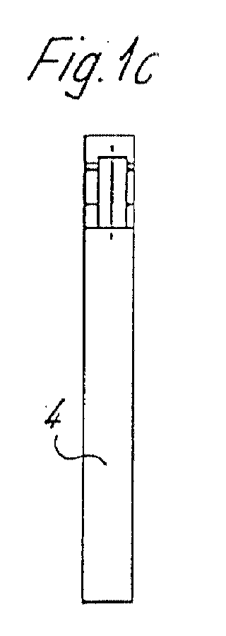
- Fig. 1c
- eine gegenüber Fig. 1b um 90° gedrehte weitere seitliche Ansicht der Reihenklemme aus Fig. 1b; und
- Fig. 1d
- eine Draufsicht auf die Reihenklemme der Fig. 1a-c; und
- Fig. 2a
- eine Seitenansicht einer zweiten erfindungsgemäßen Reihenklemme ohne seitliche Gehäuseabdeckung; und
- Fig. 2b
- einen Abschnitt eines Schnittes längs der Kante A-A aus Fig. 2a;
- Fig. 3a bis 3d
- verschiedene Ansichten einer dritten erfindungsgemäßen Reihenklemme, welche in Fig. 3a und 3c ohne Gehäusevorderseite abgebildet ist.
- Reihenklemme
- 2
- Klemmengehäuse
- 4
- Rastfüße
- 6, 8
- Anschlußvorrichtungen
- 10a, b
- Leiter
- 12
- Leitungsader
- 14
- Isolierung
- 16
- Kontaktschneide
- 18
- Stromschiene
- 20
- Kontaktierungsbereich
- 20a
- Aufweitungsschrägen
- 22
- Einführelemente
- 24
- Ausnehmung
- 26
- Federstege
- 28, 30
- Aufnahme
- 32
- Anschlag
- 34
- Öffnung
- 36
- Schraubendreher
- 38
- Sollbruchstellen
- 40, 42
- Schwenkelement
- 44
- Filmscharnier
- 46
- Einführöffnung
- 48
- Einfuhrschräge
- 50
Claims (13)
- Reihenklemme mit Schneid-Anschlußvorrichtung, die folgendes aufweist:dadurch gekennzeichnet, daßa) ein Klemmengehäuse (4) mit der wenigstens einen Schneid-Anschlußvorrichtung (10a, 10b) für jeweils mindestens einen elektrischen Leiter (12), der wenigstens eine Leitungsader (14) und eine die Leitungsader (14) umgebende Isolierung (16) aufweist,b) wobei die Anschlußvorrichtung (10a, 10b) eine, vorzugsweise im Klemmengehäuse fixierte, Kontaktschneide (18) zum Aufschneiden der Isolierung (16) des elektrischen Leiters (12) und einen Kontaktierungsbereich (20a) zur Kontaktierung der wenigstens einen Leitungsader (14) aufweist,c) ein in dem Klemmengehäuse angeordnetes und/oder einstückig mit dem Klemmengehäuse (4) ausgebildetes Einführelement (24) zum Einführen des in das Klemmengehäuse eingeführten Leiters in die Kontaktschneide und/oder den Kontaktierungsbereich (20a) vorgesehen ist, undd) daß das Klemmengehäuse (4) vorzugsweise Öffnungen (36) aufweist, welche derart bemessen sind, daß beidseits jedes Leiters (12) jeweils ein Betätigungswerkzeug wie ein Schraubendreher (38) in das Klemmengehäuse führbar ist, derart daß durch Verschwenken und/oder Verschieben des Betätigungswerkzeuges (38) der Leiter mit dem Einführelement (24) von einer Seite in die Kontaktschneide und/oder den Kontaktbereich rührbar und von der anderen Seite mit oder ohne das Einführelement (24) aus diesen lösbar ist.
- Reihenklemme nach Anspruch 1, dadurch gekennzeichnet, daß das Einführelement (24) separat zu der Anschlußvorrichtung ausgebildet ist.
- Reihenklemme nach Anspruch 1, dadurch gekennzeichnet, daß das Einführelement (24) aus Kunststoff besteht.
- Reihenklemme nach Anspruch 1, dadurch gekennzeichnet, daß das Einführelement (24) als einstückig an das Klemmengehäuse (4) angespritztes Feder- oder Einschiebeelement ausgebildet ist.
- Reihenklemme nach einem der vorstehenden Ansprüche, dadurch gekennzeichnet, daß das Federelement (24) wenigstens einen oder mehr im Klemmengehäuse (4) verschwenkbare(n) und an dieses angespritzte(n) Federsteg(e) (28, 30) und einen Anschlag (34) für den Leiter (12) aufweist, der derart ausgestaltet ist, daß durch Bewegen des Federelementes (24) der Leiter (12) am Anschlag (32) direkt in die Kontaktschneide (18) und/oder den Kontaktierungsbereich (20a) führbar ist.
- Reihenklemme nach einem der vorstehenden Ansprüche, dadurch gekennzeichnet, daß sich zwei der Federstege (28, 32) parallel zueinander vom Boden einer Ausnehmung (26) im Klemmengehäuse (4) geneigt zur Einschubrichtung des Leiters (12) bis zur Aufnahme (32) erstrecken.
- Reihenklemme nach einem der vorstehenden Ansprüche, dadurch gekennzeichnet, daß das Einführelement (24) als an das Klemmengehäuse angespritztes Einschiebeelement ausgebildet ist, welches über Sollbruchstellen (40, 42) mit dem Klemmengehäuse (4) derart verbunden ist, daß beim Bewegen des Einschiebeelementes im Klemmengehäuse (4) mit einem Betätigungswerkzeug die Sollbruchstellen (40, 42) durchtrennbar und der Leiter in die Kontaktschneide einschiebbar ist.
- Reihenklemme nach einem der vorstehenden Ansprüche, dadurch gekennzeichnet, daß das Einschiebeelement (24) in der Ausnehmung (26) senkrecht zur Tragschienenrichtung in einer Ebene parallel zur Tragschiene bewegbar ist.
- Reihenklemme nach einem der vorstehenden Ansprüche, dadurch gekennzeichnet, daß zumindestens unterhalb einer Öffnung (36) des Klemmengehäuses eine Einführschräge (50) für das Betätigungswerkzeug ausgebildet ist, welche derart ausgelegt ist, daß bereits beim Einführen des Betätigungswerkzeuges in das Klemmengehäuse das Einführelement (24) in Richtung der Kontaktschneide oder das Kontaktierungsbereiches bewegt wird.
- Reihenklemme nach einem der vorstehenden Ansprüche, dadurch gekennzeichnet, daß die Kontaktschneide (18) und der Kontaktierungsbereich (20a) aus unterschiedlichen Materialien bestehen.
- Reihenklemme nach einem der vorstehenden Ansprüche, dadurch gekennzeichnet, daß die Kontaktschneide (18) aus einem härteren Stahlmaterial und daß die Kontaktierungsbereiche als Kontaktierungsflächen (20a) ausgebildet sind, welche aus einem im Vergleich zum Stahlmaterial weicheren leitenden Material bestehen.
- Reihenklemme nach einem der vorstehenden Ansprüche, dadurch gekennzeichnet, daß die Stromschiene (20) an den beiden Enden an jeweils einer der Kontaktschneiden (18) ansetzt und eine in der Seitenansicht im wesentlichen hutförmige Geometrie aufweist.
- Reihenklemme nach einem der vorstehenden Ansprüche, dadurch gekennzeichnet, daß das Einführelement (24) über ein Filmscharnier (46) schwenkbar am Klemmengehäuse (4) gelagert ist, derart, daß das Einführelement (24) aus dem Klemmengehäuse herausschwenkbar ist.
Applications Claiming Priority (4)
| Application Number | Priority Date | Filing Date | Title |
|---|---|---|---|
| DE20001490 | 2000-01-27 | ||
| DE20001490U | 2000-01-27 | ||
| DE20006834U | 2000-04-13 | ||
| DE20006834U DE20006834U1 (de) | 2000-01-27 | 2000-04-13 | Reihenklemme mit Schneid-Anschlußvorrichtung |
Publications (2)
| Publication Number | Publication Date |
|---|---|
| EP1120859A2 true EP1120859A2 (de) | 2001-08-01 |
| EP1120859A3 EP1120859A3 (de) | 2002-06-12 |
Family
ID=26056033
Family Applications (1)
| Application Number | Title | Priority Date | Filing Date |
|---|---|---|---|
| EP01100853A Withdrawn EP1120859A3 (de) | 2000-01-27 | 2001-01-16 | Reihenklemme mit Schneid-Anschlussvorrichtung |
Country Status (1)
| Country | Link |
|---|---|
| EP (1) | EP1120859A3 (de) |
Cited By (1)
| Publication number | Priority date | Publication date | Assignee | Title |
|---|---|---|---|---|
| DE10036718B4 (de) * | 2000-07-27 | 2004-10-21 | Siemens Ag | Schneidklemmeinrichtung |
Family Cites Families (3)
| Publication number | Priority date | Publication date | Assignee | Title |
|---|---|---|---|---|
| DE2902536C2 (de) * | 1979-01-24 | 1980-12-18 | C. A. Weidmueller Kg, 4930 Detmold | Reihenklemme |
| FR2516711A1 (fr) * | 1981-11-17 | 1983-05-20 | Alsthom Cgee | Borne de raccordement de fil electrique sans denudage |
| DE29802674U1 (de) * | 1998-02-17 | 1998-04-16 | Weidmueller Interface | Reihenklemme mit isolationsdurchdringendem Leiteranschluß |
-
2001
- 2001-01-16 EP EP01100853A patent/EP1120859A3/de not_active Withdrawn
Cited By (2)
| Publication number | Priority date | Publication date | Assignee | Title |
|---|---|---|---|---|
| DE10036718B4 (de) * | 2000-07-27 | 2004-10-21 | Siemens Ag | Schneidklemmeinrichtung |
| US6918784B2 (en) | 2000-07-27 | 2005-07-19 | Siemens Aktiengesellschaft | Insulation displacement connector device with displaceable closing element |
Also Published As
| Publication number | Publication date |
|---|---|
| EP1120859A3 (de) | 2002-06-12 |
Similar Documents
| Publication | Publication Date | Title |
|---|---|---|
| EP3504755B1 (de) | Federkraftklemmanschluss | |
| EP0936697B1 (de) | Reihenklemme mit isolationsdurchdringendem Leiteranschluss | |
| DE102012005465B3 (de) | Federklemme | |
| DE68913597T2 (de) | Lötfreier elektrischer Steckverbinder. | |
| DE19641206C2 (de) | Anschlußklemme für elektrische Leiter | |
| EP0959529A2 (de) | Elektrische Anschlussbaueinheit | |
| EP2953213A1 (de) | Steckverbinderanordnung und kodierelement hierzu sowie verfahren zur kodierung einer steckverbinderanordnung | |
| EP1191633B1 (de) | Reihenklemme mit Schneidkontakten und Kontaktbetätigungsstücken | |
| EP4678976A2 (de) | Leuchte mit herauslösbarem veschlussstück | |
| DE3623258A1 (de) | Anschlusswerkzeug zum einsetzen von draehten oder litzen in loetstellenfreie verbinder | |
| DE69923492T2 (de) | Vorrichtung zur Schneidklemmverbindung von mindestens einem Draht und zum Abschneiden der freien Enden | |
| EP1753087B1 (de) | Elektrische Klemme | |
| EP1523065B1 (de) | Elektrische Klemme | |
| DE102009029434B4 (de) | Adapter zur Aufnahme elektrischer Installationsgeräte und zur Befestigung auf einem Stromschienensystem | |
| EP0069045B1 (de) | Stecksockel für mehrpolige Niederspannungs-Schutzschalter | |
| DE69918612T2 (de) | Anschlussklemme mit zwei Anschlussvorrichtungen | |
| WO1999065114A2 (de) | Anschlussklemme | |
| DE19860961C1 (de) | Elektrisches Gerät mit einer Verbindungseinrichtung zur Verbindung mit einem zweiten elektrischen Gerät | |
| EP1120859A2 (de) | Reihenklemme mit Schneid-Anschlussvorrichtung | |
| DE202015104145U1 (de) | Klemme | |
| DE102008014180A1 (de) | Trennklemme, insbesondere Neutralleiter-Trennklemme | |
| DE10238852B3 (de) | Schaltgerät | |
| DE8420661U1 (de) | Elektrischer Hilfsanschluss | |
| EP1816707A2 (de) | Anschlussleiste für elektrische Geräte, insbesondere für Stecker | |
| DE102005005917B4 (de) | Anschlussklemme für einen isolierten elektrischen Leiter |
Legal Events
| Date | Code | Title | Description |
|---|---|---|---|
| PUAI | Public reference made under article 153(3) epc to a published international application that has entered the european phase |
Free format text: ORIGINAL CODE: 0009012 |
|
| AK | Designated contracting states |
Kind code of ref document: A2 Designated state(s): AT BE CH CY DE DK ES FI FR GB GR IE IT LI LU MC NL PT SE TR |
|
| AX | Request for extension of the european patent |
Free format text: AL;LT;LV;MK;RO;SI |
|
| PUAL | Search report despatched |
Free format text: ORIGINAL CODE: 0009013 |
|
| AK | Designated contracting states |
Kind code of ref document: A3 Designated state(s): AT BE CH CY DE DK ES FI FR GB GR IE IT LI LU MC NL PT SE TR |
|
| AX | Request for extension of the european patent |
Free format text: AL;LT;LV;MK;RO;SI |
|
| 17P | Request for examination filed |
Effective date: 20020518 |
|
| AKX | Designation fees paid |
Designated state(s): AT BE CH CY DE DK ES FI FR GB GR IE IT LI LU MC NL PT SE TR |
|
| 17Q | First examination report despatched |
Effective date: 20080319 |
|
| STAA | Information on the status of an ep patent application or granted ep patent |
Free format text: STATUS: THE APPLICATION IS DEEMED TO BE WITHDRAWN |
|
| 18D | Application deemed to be withdrawn |
Effective date: 20110120 |