EP1121490B1 - Schienenhaltevorrichtung - Google Patents
Schienenhaltevorrichtung Download PDFInfo
- Publication number
- EP1121490B1 EP1121490B1 EP99948634A EP99948634A EP1121490B1 EP 1121490 B1 EP1121490 B1 EP 1121490B1 EP 99948634 A EP99948634 A EP 99948634A EP 99948634 A EP99948634 A EP 99948634A EP 1121490 B1 EP1121490 B1 EP 1121490B1
- Authority
- EP
- European Patent Office
- Prior art keywords
- clip
- bearing
- lower bearing
- rail
- abutment surface
- Prior art date
- Legal status (The legal status is an assumption and is not a legal conclusion. Google has not performed a legal analysis and makes no representation as to the accuracy of the status listed.)
- Expired - Lifetime
Links
- 238000006243 chemical reaction Methods 0.000 claims description 8
- 230000006835 compression Effects 0.000 claims description 3
- 238000007906 compression Methods 0.000 claims description 3
- 238000009434 installation Methods 0.000 description 5
- RAQQRQCODVNJCK-JLHYYAGUSA-N N-[(4-amino-2-methylpyrimidin-5-yl)methyl]-N-[(E)-5-hydroxy-3-(2-hydroxyethyldisulfanyl)pent-2-en-2-yl]formamide Chemical compound C\C(N(Cc1cnc(C)nc1N)C=O)=C(\CCO)SSCCO RAQQRQCODVNJCK-JLHYYAGUSA-N 0.000 description 2
- 230000005012 migration Effects 0.000 description 2
- 238000013508 migration Methods 0.000 description 2
- 230000002028 premature Effects 0.000 description 2
- 229910000831 Steel Inorganic materials 0.000 description 1
- 230000032798 delamination Effects 0.000 description 1
- 238000010348 incorporation Methods 0.000 description 1
- 239000012212 insulator Substances 0.000 description 1
- 239000000615 nonconductor Substances 0.000 description 1
- 230000010355 oscillation Effects 0.000 description 1
- 238000009877 rendering Methods 0.000 description 1
- 239000010959 steel Substances 0.000 description 1
Images


Classifications
-
- E—FIXED CONSTRUCTIONS
- E01—CONSTRUCTION OF ROADS, RAILWAYS, OR BRIDGES
- E01B—PERMANENT WAY; PERMANENT-WAY TOOLS; MACHINES FOR MAKING RAILWAYS OF ALL KINDS
- E01B9/00—Fastening rails on sleepers, or the like
- E01B9/38—Indirect fastening of rails by using tie-plates or chairs; Fastening of rails on the tie-plates or in the chairs
- E01B9/44—Fastening the rail on the tie-plate
- E01B9/46—Fastening the rail on the tie-plate by clamps
- E01B9/48—Fastening the rail on the tie-plate by clamps by resilient steel clips
- E01B9/483—Fastening the rail on the tie-plate by clamps by resilient steel clips the clip being a shaped bar
-
- E—FIXED CONSTRUCTIONS
- E01—CONSTRUCTION OF ROADS, RAILWAYS, OR BRIDGES
- E01B—PERMANENT WAY; PERMANENT-WAY TOOLS; MACHINES FOR MAKING RAILWAYS OF ALL KINDS
- E01B3/00—Transverse or longitudinal sleepers; Other means resting directly on the ballastway for supporting rails
- E01B3/16—Transverse or longitudinal sleepers; Other means resting directly on the ballastway for supporting rails made from steel
-
- E—FIXED CONSTRUCTIONS
- E01—CONSTRUCTION OF ROADS, RAILWAYS, OR BRIDGES
- E01B—PERMANENT WAY; PERMANENT-WAY TOOLS; MACHINES FOR MAKING RAILWAYS OF ALL KINDS
- E01B9/00—Fastening rails on sleepers, or the like
- E01B9/02—Fastening rails, tie-plates, or chairs directly on sleepers or foundations; Means therefor
- E01B9/28—Fastening on wooden or concrete sleepers or on masonry with clamp members
- E01B9/30—Fastening on wooden or concrete sleepers or on masonry with clamp members by resilient steel clips
- E01B9/303—Fastening on wooden or concrete sleepers or on masonry with clamp members by resilient steel clips the clip being a shaped bar
-
- E—FIXED CONSTRUCTIONS
- E01—CONSTRUCTION OF ROADS, RAILWAYS, OR BRIDGES
- E01B—PERMANENT WAY; PERMANENT-WAY TOOLS; MACHINES FOR MAKING RAILWAYS OF ALL KINDS
- E01B2205/00—Electrical insulation of railway track parts
Definitions
- the present invention relates to rail retaining devices for incorporation in a rail track.
- the invention provides a rail retaining device comprising a shoulder member for bearing on a lateral side of a rail flange, and providing a downwardly facing abutment surface, and a rail clip for extending laterally of the rail and having an inner portion for bearing on an adjacent rail flange in an installed position, an intermediate portion for bearing upwardly on said abutment surface, and an outer portion connected to the intermediate portion for extending outwardly from said abutment surface to a lower bearing portion adapted to bear on a bearing surface, characterized in that the clip is in the form of a bent rod having a pair of outer free end portions interconnected by a looped innermost portion, said bent rod being symmetrical about a vertical plane, said inner portion being formed by said looped innermost portion, and said outer portion being formed by said outer free end portions, said outer free end portions being curved downwardly and folded back inwardly toward said looped innermost portion to provide a pair of lower bearing portions adapted to bear on said bearing surface, and wherein in said installed position
- the arrangement of the invention provides excellent stress distribution and avoids stress concentrations that can contribute to premature failure in known clips. Further, the clip is compliant and tolerant of dimensional variation in the components and is relatively easily to install, while providing a highly effective and durable rail retaining function.
- the lower bearing portion of the clip is adapted to bear on the bearing surface at a region that is offset laterally inwardly from a centre of curvature of the outer portion. This further improves the stress distribution through the clip in service.
- the inner portion comprises an upwardly bowed portion adjacent the abutment surface that provides increased resistance to migration of the clip outwardly from its installed position as a result of impacts or vibration encountered in service.
- each lower portion of said outer portions inclines longitudinally with respect to said vertical plane, whereby squatting of the outer portion is facilitated during installation, rendering the clip particularly compliant and facilitating installation.
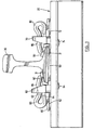
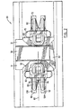
- FIGS. 1 to 3 show a fastening arrangement employing a steel tie 20, electrically insulating cant plate 50 and hook-in field and gauge shoulder members 60 and 70, respectively, these elements being generally as and installed as described in, applicant's published application WO 96/23107, which should be referred to for further details.
- clips 80 extend through openings 61 and 71 in the shoulder members 60 and 70, respectively, and bear upwardly on a downwardly facing abutment surface provided on an upper side of the opening 61 or 71, for example on surface 62 as shown in broken lines in Fig.1.
- An end portion 81 of the clip 80, disposed laterally inwardly of the clip 80 with respect to a rail 30 bears on a rail flange 31 either directly, or, more usually, through an electrical insulator pad 90 interposed between the rail flange 31 on the one hand and the clip 80 and the shoulder 60 or 70 on the other.
- a laterally outer end of the clip 80 engages on a bearing surface, for example a laterally outer extension 63 or 73 of the shoulder 60 or 70.
- a bearing surface for example a laterally outer extension 63 or 73 of the shoulder 60 or 70.
- FIG. 1 Also visible in Fig. 1 are the hook-in leg portions 64 and 74 formal integrally with shoulders 60 and 70, respectively, and that are passed through openings in the tie 20 and secure the shoulder portions 60 and 70, to the tie 20.
- the hook-in leg portions 64 and 74 formal integrally with shoulders 60 and 70, respectively, and that are passed through openings in the tie 20 and secure the shoulder portions 60 and 70, to the tie 20.
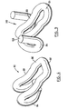
- the clip 80 is of bent rod form.
- This bent rod clip 80 has an advantage over similar plate form clips that it is not subject to failure by delamination.
- the clip 80 is symmetrical about a vertical plane 82, indicated in Fig. 2, extending laterally of the rail 30, with the inner portion 81 for bearing on the rail flange, intermediate limb portions 83 for engaging upwardly on the downwardly facing abutment surface such as surface 62, and an outer portion 84 curving laterally arcuately outwardly and downwardly and for bearing on a bearing surface such as an upper surface 66 of the extension 62 or 72.
- the downwardly facing abutment surface engages the intermediate portions 83 of the clip 80 and the downward reaction with the surface 62 flexes the portions 83 downwardly with respect to the inner and outer portions 81 and 84.
- the reaction at the inner portion 81 applies a toe load to the flange 31 while the outer portion 84 tends to flex resulting in compression of the outer portion.
- the inner portion 81 of the clip 80 includes upwardly bowed portions 86 that reacts with the surface 62 to provide a reaction having an inwardly directed component of force on uplift of the rail flange 31, so that vertical vibration or oscillation of the flange 31 creates forces tending to resist migration of the clip 80 outwardly from the shoulder 60 or 70.
- the non-compressed or free, non-installed condition of the clip 80 as best seen in Fig.
- a sloping side of the upwardly bowed portion 86, or a line T down tangentially to the portion 86 at its side adjacent the surface 63, defines with the lower side of the lower portion 84 (or a line S drawn tangentical to the lowermost portion thereof)a positive angle ⁇ .
- each lower portion 84 inclines longitudinally with respect to the vertical plane 82, so that during installation, when the clip 80 is driven inwardly through the opening 61 or 71, the portions 84 can twist sideways relative to the remainder of the clip 80, so that the lower outer portion of the clip 80 compresses or squats.
- the portions 84 are toed inwardly. Once installed, the clip 80 of Figs. 1 to 4 resists rail uplift since squatting is limited by the portions 84 approaching and touching one another.
- clip 100 shown in Figs. 5 to 8 the lower portions 107 are toed outwardly.
- This arrangement provides a wider footprint and greater stability for the clip during installation, and reduces any tendency for the clip to spring outwardly from the shoulder when driven inwardly relative to the shoulder.
- the clip 100 is otherwise similar to that described above with reference to Figs. 1 to 4.
- Clip 100 may be used with shoulders having extensions such as extensions 63, having anti-squat side wall members, such as raised walls 108 as seen in Fig. 3, disposed longitudinally outwardly from lower portions 107.
- the walls 108 limit outward movement of portions 107 and limit the extent of squatting when uplift of the flange 31 occurs.
- Clip 110 shown in Fig. 9 is similar to clips 100 except extensions of lower portion 84 or end portions 108 extend upwardly and abut the outer side of the shoulder and extend above the upper edge of the shoulder such as shoulder 60 in the installed position. The exposed upper ends of the portion 108 may be engaged by tools to facilitate removal of the clips when desired.
- the clips 80, 100 and 110 may be installed by laying their inner ends 81 loosely in the openings 61 or 71 and driving the clips inwardly with an inwardly directed force applied to the end of the outer portions until the upwardly bowed portion snaps past downwardly facing abutment surface such as surface 62 as the inner end portion 81 rides up the flange 31 or pre-installed insulator 90, and the intermediate portion 83 is flexed resiliently downwardly.
Landscapes
- Engineering & Computer Science (AREA)
- Architecture (AREA)
- Civil Engineering (AREA)
- Structural Engineering (AREA)
- Mechanical Engineering (AREA)
- Railway Tracks (AREA)
- Electrical Discharge Machining, Electrochemical Machining, And Combined Machining (AREA)
- Spinning Or Twisting Of Yarns (AREA)
- Connections Arranged To Contact A Plurality Of Conductors (AREA)
Claims (9)
- Schienenhaltevorrichtung, die ein Schulterelement (60, 70) das an einer seitlichen Seite eines Schienenfußes (31) anliegt und eine nach unten zeigende Widerlagerfläche (62) bereitstellt, und eine Schienenklemme (80) umfaßt, die sich seitlich von der Schiene erstreckt und einen Innenabschnitt (81), der in einer Einbauposition an einem benachbarten Schienenfuß (31) anliegt, einen Zwischenabschnitt (83), der nach oben an der Widerlagerfläche (62) anliegt und einen mit dem Zwischenabschnitt verbundenen Außenabschnitt hat, der sich von der Widerlagerfläche (62) nach außen bis zu einem unteren Lagerabschnitt (84) erstreckt, geeignet, an einer Lagerfläche (63) anzuliegen, dadurch gekennzeichnet, daß die Klemme (80) die Form einer gebogenen Stange mit einem Paar äußerer freier Endabschnitte hat, die durch einen schleifenförmigen innersten Abschnitt miteinander verbunden werden, wobei die gebogene Stange um eine vertikale Ebene symmetrisch ist, der Innenabschnitt (81) durch den schleifenförmigen innersten Abschnitt gebildet wird und der Außenabschnitt durch die äußeren freien Endabschnitte gebildet wird, wobei die äußeren freien Endabschnitte nach außen gekrümmt und zu dem schleifenförmigen innersten Abschnitt hin umgeklappt werden, um ein Paar unterer Lagerabschnitte (84) bereitzustellen, geeignet, an der Lagerfläche (63) anzuliegen, und wobei es in der Einbauposition eine Reaktion zwischen dem Zwischenabschnitt (83) und der Widerlagerfläche gibt, die bewirkt, daß der schleifenförmige innerste Abschnitt eine Spitzenbelastung auf den benachbarten Schienenfuß (31) ausübt und der Außenabschnitt zusammengedrückt wird.
- Vorrichtung nach Anspruch 1, dadurch gekennzeichnet, daß der untere Lagerabschnitt (84) der Klemme (80) geeignet ist, in einem von einem Krümmungsmittelpunkt des Außenabschnitts seitlich nach innen versetzten Bereich an der Lagerfläche (63) anzuliegen.
- Vorrichtung nach Anspruch 1 oder 2, dadurch gekennzeichnet, daß der Innenabschnitt der Klemme einen nach oben gewölbten Abschnitt (86) hat, der in der Einbauposition an die Widerlagerfläche angrenzt.
- Vorrichtung nach Anspruch 3, dadurch gekennzeichnet, daß der nach oben gewölbte Abschnitt (86) in einem nicht eingebauten Zustand der Klemme einen positiven Winkel mit einer unteren Lagerfläche des unteren Lagerabschnitts (84) bildet.
- Vorrichtung nach einem der Ansprüche 1 bis 4, dadurch gekennzeichnet, daß sich jeder untere Lagerabschnitt (84) in Längsrichtung im Verhältnis zu der vertikalen Ebene neigt.
- Vorrichtung nach Anspruch 5, dadurch gekennzeichnet, daß sich jeder untere Lagerabschnitt (84) in Längsrichtung nach außen, in einer Richtung seitlich nach innen neigt.
- Vorrichtung nach Anspruch 6, die ein mit dem Schulterelement (60, 70) verbundenes Wandelement einschließt, von jedem unteren Lagerabschnitt (84) in Längsrichtung nach außen, um eine Auswärtsbewegung desselben zu begrenzen.
- Vorrichtung nach einem der vorhergehenden Ansprüche, dadurch gekennzeichnet, daß sich jeder untere Lagerabschnitt (84) in einer Verlängerung nach unten und nach innen fortsetzt, die sich in der Einbauposition oberhalb einer Unterkante des Schulterelements (60, 70) erstreckt.
- Vorrichtung nach einem der Ansprüche 1 bis 7, dadurch gekennzeichnet, daß die unteren Lagerabschnitte (84) gerade Endsegmente der gebogenen Stange einschließen, die über einen wesentlichen Teil ihrer Länge an den Lagerflächen (63) anliegen.
Applications Claiming Priority (3)
| Application Number | Priority Date | Filing Date | Title |
|---|---|---|---|
| CA002270299A CA2270299A1 (en) | 1998-10-14 | 1998-10-14 | Rail retaining device |
| CA2270299 | 1998-10-14 | ||
| PCT/CA1999/000966 WO2000022235A1 (en) | 1998-10-14 | 1999-10-13 | Rail retaining device |
Publications (2)
| Publication Number | Publication Date |
|---|---|
| EP1121490A1 EP1121490A1 (de) | 2001-08-08 |
| EP1121490B1 true EP1121490B1 (de) | 2005-08-17 |
Family
ID=4163490
Family Applications (1)
| Application Number | Title | Priority Date | Filing Date |
|---|---|---|---|
| EP99948634A Expired - Lifetime EP1121490B1 (de) | 1998-10-14 | 1999-10-13 | Schienenhaltevorrichtung |
Country Status (7)
| Country | Link |
|---|---|
| US (1) | US6702192B2 (de) |
| EP (1) | EP1121490B1 (de) |
| AT (1) | ATE302304T1 (de) |
| AU (1) | AU6185099A (de) |
| CA (1) | CA2270299A1 (de) |
| DE (1) | DE69926772T2 (de) |
| WO (1) | WO2000022235A1 (de) |
Families Citing this family (16)
| Publication number | Priority date | Publication date | Assignee | Title |
|---|---|---|---|---|
| CA2270299A1 (en) | 1998-10-14 | 2000-04-14 | Jude Igwemezie | Rail retaining device |
| US6603955B2 (en) * | 2001-06-27 | 2003-08-05 | Harry E. Gruber | Mission certification quiz for fundraising campaign |
| GB2388141B (en) * | 2002-04-30 | 2005-05-25 | Pandrol Ltd | Railway rail fastening clip |
| DE102005048829A1 (de) * | 2004-12-09 | 2006-06-29 | SCHWIHAG GESELLSCHAFT FüR EISENBAHNOBERBAU MBH | Kraftschlüssig-elastische Schienenbefestigung für Gleisanlagen |
| US20100270386A1 (en) * | 2005-08-15 | 2010-10-28 | Portec Rail Products, Inc. | Bolt on Continuous Rail Joint |
| DE102005058444B3 (de) * | 2005-12-07 | 2007-04-26 | Db Netz Ag | Befestigungsmittel für Bahnschienen |
| CA2567903C (en) * | 2005-12-15 | 2014-01-28 | Airboss Railway Products Inc. | Improved rail insulators |
| GB2435285A (en) * | 2006-02-21 | 2007-08-22 | Pandrol Ltd | Fastening railway rails |
| US20090057435A1 (en) * | 2007-08-27 | 2009-03-05 | Jude Igwemezie | P-clip clip for retaining rails |
| US8375544B1 (en) * | 2008-10-17 | 2013-02-19 | Portaco, Inc. | Railroad pin removal system |
| US20100170955A1 (en) * | 2009-01-07 | 2010-07-08 | Jude Odihachukwuma Igwemezie | Concrete Tie Fastener |
| GB0905918D0 (en) * | 2009-04-06 | 2009-05-20 | Pandrol Ltd | Fastening railway rails |
| GB201103327D0 (de) * | 2011-02-28 | 2011-04-13 | Pandrol Ltd | |
| GB2502990B (en) | 2012-06-12 | 2018-01-31 | Pandrol Ltd | Railway rail fastening clip for recessed railseats |
| DE102013106123A1 (de) * | 2013-06-12 | 2014-12-18 | Vossloh-Werke Gmbh | Schienenbefestigungspunkt und Unterlegplatte für einen solchen Schienenbefestigungspunkt |
| LT3346054T (lt) | 2017-01-10 | 2022-01-25 | Schwihag Ag | Įtempimo veržiklis ir bėgių tvirtinimo sistema, skirta geležinkelio bėgiams tvirtinti |
Family Cites Families (14)
| Publication number | Priority date | Publication date | Assignee | Title |
|---|---|---|---|---|
| US3021076A (en) * | 1957-12-19 | 1962-02-13 | True Temper Corp | Rail anchors |
| AU528374B2 (en) * | 1978-06-02 | 1983-04-28 | Omark Industries, Inc. | Rail clip |
| ZA849298B (en) * | 1983-12-21 | 1985-07-31 | Mckay Ralph Ltd | Rail clip support |
| AU630250B2 (en) * | 1989-11-13 | 1992-10-22 | General And Railway Supplies Pty Ltd | Resilient rail retaining clip |
| US5735458A (en) * | 1991-12-18 | 1998-04-07 | Pandrol Limited | Fastening railway rails |
| IN185922B (de) | 1991-12-18 | 2001-05-19 | Pandrol Ltd | |
| GB9415981D0 (en) * | 1994-08-08 | 1994-09-28 | Pandrol Ltd | Elastic rail clamp |
| BR9607185A (pt) * | 1995-01-13 | 1997-11-11 | Jude O Igwemezie | Dispositivos de fixação de trilhos |
| TR199801560T2 (xx) | 1996-02-13 | 1998-11-23 | Pandrol Limited | Esnek ray kıskaçların üretimi. |
| EE9700257A (et) | 1996-02-13 | 1998-04-15 | Pandrol Limited | Elastne rööpaklamber |
| WO1997036055A1 (en) | 1996-03-27 | 1997-10-02 | Pandrol Limited | Railway rail fastening assemblies including resilient railway rail fastening clips and associated insulators |
| GB9623107D0 (en) | 1996-11-06 | 1997-01-08 | Biochemie Gmbh | Organic compounds |
| GB2358034B (en) | 1997-07-15 | 2001-09-26 | Pandrol Ltd | Railway rail fastening assembly |
| CA2270299A1 (en) | 1998-10-14 | 2000-04-14 | Jude Igwemezie | Rail retaining device |
-
1998
- 1998-10-14 CA CA002270299A patent/CA2270299A1/en not_active Abandoned
-
1999
- 1999-10-13 EP EP99948634A patent/EP1121490B1/de not_active Expired - Lifetime
- 1999-10-13 WO PCT/CA1999/000966 patent/WO2000022235A1/en not_active Ceased
- 1999-10-13 AU AU61850/99A patent/AU6185099A/en not_active Abandoned
- 1999-10-13 DE DE69926772T patent/DE69926772T2/de not_active Expired - Fee Related
- 1999-10-13 AT AT99948634T patent/ATE302304T1/de not_active IP Right Cessation
-
2001
- 2001-04-12 US US09/834,094 patent/US6702192B2/en not_active Expired - Fee Related
Also Published As
| Publication number | Publication date |
|---|---|
| WO2000022235A1 (en) | 2000-04-20 |
| AU6185099A (en) | 2000-05-01 |
| EP1121490A1 (de) | 2001-08-08 |
| US6702192B2 (en) | 2004-03-09 |
| DE69926772D1 (de) | 2005-09-22 |
| CA2270299A1 (en) | 2000-04-14 |
| ATE302304T1 (de) | 2005-09-15 |
| US20020000475A1 (en) | 2002-01-03 |
| DE69926772T2 (de) | 2006-05-18 |
Similar Documents
| Publication | Publication Date | Title |
|---|---|---|
| US6702192B2 (en) | Rail retaining device | |
| AU2007217202B2 (en) | Railway rail fastening clip | |
| US9290888B2 (en) | Rail-fastening system | |
| CN103270219B (zh) | 用于侧面引导轨道的引导板和用于轨道固定的系统 | |
| US6431463B2 (en) | Rail fastening devices | |
| CN102498245B (zh) | 用于固定轨道的系统和轨道的固定装置 | |
| US4826078A (en) | Wire-to-track-base retainer clip and keeper | |
| US5782406A (en) | Rail tie plate clips and shoulders | |
| US6923381B2 (en) | Railway rail fastening clip and assembly | |
| US6367704B1 (en) | Rail fastening system constructed to allow pre-assembly of a rail clip and shoulder | |
| US4399941A (en) | Rail clamp | |
| US4511081A (en) | Rail anchoring clip and associated sleeper | |
| AU713004B2 (en) | Rail fastening devices | |
| CA2347486A1 (en) | Rail retaining device | |
| JPH02140301A (ja) | レールと枕木とを固定する装置 | |
| GB2358034A (en) | A railway rail fastening assembly | |
| CA2210395C (en) | Rail fastening devices | |
| GB2261241A (en) | Railway rail fastening assembly | |
| WO2001073203A1 (en) | Rail insulator | |
| KR100187149B1 (ko) | 와셔 겸용 너트 클립 | |
| RU2156332C2 (ru) | Устройство для крепления рельса | |
| KR830001191Y1 (ko) | 철도레일 고정 스프링 크립의 괘착구 | |
| KR200208333Y1 (ko) | 현접법에의한 궤도 이음매부 절연체결장치 | |
| EP1273709A2 (de) | Eisenbahnschienenbefestigungssystem | |
| RU2307884C1 (ru) | Устройство для крепления рельса к шпале |
Legal Events
| Date | Code | Title | Description |
|---|---|---|---|
| PUAI | Public reference made under article 153(3) epc to a published international application that has entered the european phase |
Free format text: ORIGINAL CODE: 0009012 |
|
| 17P | Request for examination filed |
Effective date: 20010514 |
|
| AK | Designated contracting states |
Kind code of ref document: A1 Designated state(s): AT BE CH CY DE DK ES FI FR GB GR IE IT LI LU MC NL PT SE |
|
| 17Q | First examination report despatched |
Effective date: 20040203 |
|
| GRAJ | Information related to disapproval of communication of intention to grant by the applicant or resumption of examination proceedings by the epo deleted |
Free format text: ORIGINAL CODE: EPIDOSDIGR1 |
|
| GRAP | Despatch of communication of intention to grant a patent |
Free format text: ORIGINAL CODE: EPIDOSNIGR1 |
|
| GRAP | Despatch of communication of intention to grant a patent |
Free format text: ORIGINAL CODE: EPIDOSNIGR1 |
|
| GRAS | Grant fee paid |
Free format text: ORIGINAL CODE: EPIDOSNIGR3 |
|
| GRAA | (expected) grant |
Free format text: ORIGINAL CODE: 0009210 |
|
| AK | Designated contracting states |
Kind code of ref document: B1 Designated state(s): AT BE CH CY DE DK ES FI FR GB GR IE IT LI LU MC NL PT SE |
|
| PG25 | Lapsed in a contracting state [announced via postgrant information from national office to epo] |
Ref country code: NL Free format text: LAPSE BECAUSE OF FAILURE TO SUBMIT A TRANSLATION OF THE DESCRIPTION OR TO PAY THE FEE WITHIN THE PRESCRIBED TIME-LIMIT Effective date: 20050817 Ref country code: LI Free format text: LAPSE BECAUSE OF FAILURE TO SUBMIT A TRANSLATION OF THE DESCRIPTION OR TO PAY THE FEE WITHIN THE PRESCRIBED TIME-LIMIT Effective date: 20050817 Ref country code: IT Free format text: LAPSE BECAUSE OF FAILURE TO SUBMIT A TRANSLATION OF THE DESCRIPTION OR TO PAY THE FEE WITHIN THE PRESCRIBED TIME-LIMIT;WARNING: LAPSES OF ITALIAN PATENTS WITH EFFECTIVE DATE BEFORE 2007 MAY HAVE OCCURRED AT ANY TIME BEFORE 2007. THE CORRECT EFFECTIVE DATE MAY BE DIFFERENT FROM THE ONE RECORDED. Effective date: 20050817 Ref country code: FI Free format text: LAPSE BECAUSE OF FAILURE TO SUBMIT A TRANSLATION OF THE DESCRIPTION OR TO PAY THE FEE WITHIN THE PRESCRIBED TIME-LIMIT Effective date: 20050817 Ref country code: CH Free format text: LAPSE BECAUSE OF FAILURE TO SUBMIT A TRANSLATION OF THE DESCRIPTION OR TO PAY THE FEE WITHIN THE PRESCRIBED TIME-LIMIT Effective date: 20050817 Ref country code: BE Free format text: LAPSE BECAUSE OF FAILURE TO SUBMIT A TRANSLATION OF THE DESCRIPTION OR TO PAY THE FEE WITHIN THE PRESCRIBED TIME-LIMIT Effective date: 20050817 Ref country code: AT Free format text: LAPSE BECAUSE OF FAILURE TO SUBMIT A TRANSLATION OF THE DESCRIPTION OR TO PAY THE FEE WITHIN THE PRESCRIBED TIME-LIMIT Effective date: 20050817 |
|
| REG | Reference to a national code |
Ref country code: GB Ref legal event code: FG4D |
|
| REG | Reference to a national code |
Ref country code: CH Ref legal event code: EP |
|
| REG | Reference to a national code |
Ref country code: IE Ref legal event code: FG4D |
|
| REF | Corresponds to: |
Ref document number: 69926772 Country of ref document: DE Date of ref document: 20050922 Kind code of ref document: P |
|
| PG25 | Lapsed in a contracting state [announced via postgrant information from national office to epo] |
Ref country code: IE Free format text: LAPSE BECAUSE OF NON-PAYMENT OF DUE FEES Effective date: 20051013 Ref country code: CY Free format text: LAPSE BECAUSE OF FAILURE TO SUBMIT A TRANSLATION OF THE DESCRIPTION OR TO PAY THE FEE WITHIN THE PRESCRIBED TIME-LIMIT Effective date: 20051013 |
|
| PGFP | Annual fee paid to national office [announced via postgrant information from national office to epo] |
Ref country code: GB Payment date: 20051019 Year of fee payment: 7 |
|
| PGFP | Annual fee paid to national office [announced via postgrant information from national office to epo] |
Ref country code: DE Payment date: 20051020 Year of fee payment: 7 |
|
| PGFP | Annual fee paid to national office [announced via postgrant information from national office to epo] |
Ref country code: FR Payment date: 20051025 Year of fee payment: 7 |
|
| PG25 | Lapsed in a contracting state [announced via postgrant information from national office to epo] |
Ref country code: MC Free format text: LAPSE BECAUSE OF NON-PAYMENT OF DUE FEES Effective date: 20051031 Ref country code: LU Free format text: LAPSE BECAUSE OF NON-PAYMENT OF DUE FEES Effective date: 20051031 |
|
| PG25 | Lapsed in a contracting state [announced via postgrant information from national office to epo] |
Ref country code: SE Free format text: LAPSE BECAUSE OF FAILURE TO SUBMIT A TRANSLATION OF THE DESCRIPTION OR TO PAY THE FEE WITHIN THE PRESCRIBED TIME-LIMIT Effective date: 20051117 Ref country code: GR Free format text: LAPSE BECAUSE OF FAILURE TO SUBMIT A TRANSLATION OF THE DESCRIPTION OR TO PAY THE FEE WITHIN THE PRESCRIBED TIME-LIMIT Effective date: 20051117 Ref country code: DK Free format text: LAPSE BECAUSE OF FAILURE TO SUBMIT A TRANSLATION OF THE DESCRIPTION OR TO PAY THE FEE WITHIN THE PRESCRIBED TIME-LIMIT Effective date: 20051117 |
|
| PG25 | Lapsed in a contracting state [announced via postgrant information from national office to epo] |
Ref country code: ES Free format text: LAPSE BECAUSE OF FAILURE TO SUBMIT A TRANSLATION OF THE DESCRIPTION OR TO PAY THE FEE WITHIN THE PRESCRIBED TIME-LIMIT Effective date: 20051128 |
|
| PG25 | Lapsed in a contracting state [announced via postgrant information from national office to epo] |
Ref country code: PT Free format text: LAPSE BECAUSE OF FAILURE TO SUBMIT A TRANSLATION OF THE DESCRIPTION OR TO PAY THE FEE WITHIN THE PRESCRIBED TIME-LIMIT Effective date: 20060117 |
|
| NLV1 | Nl: lapsed or annulled due to failure to fulfill the requirements of art. 29p and 29m of the patents act | ||
| REG | Reference to a national code |
Ref country code: CH Ref legal event code: PL |
|
| ET | Fr: translation filed | ||
| PLBE | No opposition filed within time limit |
Free format text: ORIGINAL CODE: 0009261 |
|
| STAA | Information on the status of an ep patent application or granted ep patent |
Free format text: STATUS: NO OPPOSITION FILED WITHIN TIME LIMIT |
|
| 26N | No opposition filed |
Effective date: 20060518 |
|
| REG | Reference to a national code |
Ref country code: IE Ref legal event code: MM4A |
|
| PG25 | Lapsed in a contracting state [announced via postgrant information from national office to epo] |
Ref country code: DE Free format text: LAPSE BECAUSE OF NON-PAYMENT OF DUE FEES Effective date: 20070501 |
|
| GBPC | Gb: european patent ceased through non-payment of renewal fee |
Effective date: 20061013 |
|
| REG | Reference to a national code |
Ref country code: FR Ref legal event code: ST Effective date: 20070629 |
|
| PG25 | Lapsed in a contracting state [announced via postgrant information from national office to epo] |
Ref country code: GB Free format text: LAPSE BECAUSE OF NON-PAYMENT OF DUE FEES Effective date: 20061013 |
|
| PG25 | Lapsed in a contracting state [announced via postgrant information from national office to epo] |
Ref country code: FR Free format text: LAPSE BECAUSE OF NON-PAYMENT OF DUE FEES Effective date: 20061031 |