EP1122000A1 - Process for the manufacture of a torsion spring arrangement and torsion spring arrangement - Google Patents
Process for the manufacture of a torsion spring arrangement and torsion spring arrangement Download PDFInfo
- Publication number
- EP1122000A1 EP1122000A1 EP00101993A EP00101993A EP1122000A1 EP 1122000 A1 EP1122000 A1 EP 1122000A1 EP 00101993 A EP00101993 A EP 00101993A EP 00101993 A EP00101993 A EP 00101993A EP 1122000 A1 EP1122000 A1 EP 1122000A1
- Authority
- EP
- European Patent Office
- Prior art keywords
- torsion spring
- spring
- torsion
- annular space
- pipe section
- Prior art date
- Legal status (The legal status is an assumption and is not a legal conclusion. Google has not performed a legal analysis and makes no representation as to the accuracy of the status listed.)
- Withdrawn
Links
- 238000000034 method Methods 0.000 title claims abstract description 30
- 238000004519 manufacturing process Methods 0.000 title claims description 8
- 239000000126 substance Substances 0.000 claims description 26
- 229910000639 Spring steel Inorganic materials 0.000 claims description 15
- 239000006260 foam Substances 0.000 claims description 12
- 239000000314 lubricant Substances 0.000 claims description 5
- 230000007423 decrease Effects 0.000 claims description 2
- 230000003247 decreasing effect Effects 0.000 claims description 2
- 239000000463 material Substances 0.000 abstract description 2
- 238000005253 cladding Methods 0.000 abstract 2
- 238000009423 ventilation Methods 0.000 description 4
- 238000004804 winding Methods 0.000 description 4
- 239000003795 chemical substances by application Substances 0.000 description 3
- 238000002347 injection Methods 0.000 description 3
- 239000007924 injection Substances 0.000 description 3
- 238000013016 damping Methods 0.000 description 2
- 230000005489 elastic deformation Effects 0.000 description 2
- 238000005187 foaming Methods 0.000 description 2
- 238000003780 insertion Methods 0.000 description 2
- 230000037431 insertion Effects 0.000 description 2
- 239000011159 matrix material Substances 0.000 description 2
- 238000007789 sealing Methods 0.000 description 2
- 238000005299 abrasion Methods 0.000 description 1
- 238000004026 adhesive bonding Methods 0.000 description 1
- 230000015572 biosynthetic process Effects 0.000 description 1
- 238000007796 conventional method Methods 0.000 description 1
- 230000008878 coupling Effects 0.000 description 1
- 238000010168 coupling process Methods 0.000 description 1
- 238000005859 coupling reaction Methods 0.000 description 1
- 238000011161 development Methods 0.000 description 1
- 230000018109 developmental process Effects 0.000 description 1
- 238000009434 installation Methods 0.000 description 1
- 239000007787 solid Substances 0.000 description 1
- 239000007921 spray Substances 0.000 description 1
- 238000005507 spraying Methods 0.000 description 1
- 230000001629 suppression Effects 0.000 description 1
Images


Classifications
-
- B—PERFORMING OPERATIONS; TRANSPORTING
- B21—MECHANICAL METAL-WORKING WITHOUT ESSENTIALLY REMOVING MATERIAL; PUNCHING METAL
- B21F—WORKING OR PROCESSING OF METAL WIRE
- B21F35/00—Making springs from wire
- B21F35/02—Bending or deforming ends of coil springs to special shape
-
- F—MECHANICAL ENGINEERING; LIGHTING; HEATING; WEAPONS; BLASTING
- F16—ENGINEERING ELEMENTS AND UNITS; GENERAL MEASURES FOR PRODUCING AND MAINTAINING EFFECTIVE FUNCTIONING OF MACHINES OR INSTALLATIONS; THERMAL INSULATION IN GENERAL
- F16F—SPRINGS; SHOCK-ABSORBERS; MEANS FOR DAMPING VIBRATION
- F16F1/00—Springs
- F16F1/02—Springs made of steel or other material having low internal friction; Wound, torsion, leaf, cup, ring or the like springs, the material of the spring not being relevant
- F16F1/04—Wound springs
- F16F1/12—Attachments or mountings
- F16F1/127—Attachments or mountings allowing rotation about axis of spring
-
- F—MECHANICAL ENGINEERING; LIGHTING; HEATING; WEAPONS; BLASTING
- F16—ENGINEERING ELEMENTS AND UNITS; GENERAL MEASURES FOR PRODUCING AND MAINTAINING EFFECTIVE FUNCTIONING OF MACHINES OR INSTALLATIONS; THERMAL INSULATION IN GENERAL
- F16F—SPRINGS; SHOCK-ABSORBERS; MEANS FOR DAMPING VIBRATION
- F16F1/00—Springs
- F16F1/02—Springs made of steel or other material having low internal friction; Wound, torsion, leaf, cup, ring or the like springs, the material of the spring not being relevant
- F16F1/14—Torsion springs consisting of bars or tubes
-
- F—MECHANICAL ENGINEERING; LIGHTING; HEATING; WEAPONS; BLASTING
- F16—ENGINEERING ELEMENTS AND UNITS; GENERAL MEASURES FOR PRODUCING AND MAINTAINING EFFECTIVE FUNCTIONING OF MACHINES OR INSTALLATIONS; THERMAL INSULATION IN GENERAL
- F16F—SPRINGS; SHOCK-ABSORBERS; MEANS FOR DAMPING VIBRATION
- F16F3/00—Spring units consisting of several springs, e.g. for obtaining a desired spring characteristic
Definitions
- the invention relates to a method of manufacture a torsion spring arrangement with an elongated, from Spring steel wire wound or coiled and high Number of turns torsion spring and one in the free Cross section of the torsion spring arranged support sleeve for the Torsion spring to suppress warping on torsion claimed torsion spring, wherein a pipe section in the Torsion spring is introduced.
- the Invention on a torsion spring arrangement with an elongated, made of spring steel wire or wound and a high number of turns torsion spring and an in the free cross section of the torsion spring arranged support sleeve for the torsion spring to suppress warpage the torsion spring stressed on torsion, the carrier sleeve has a hard core.
- Torsion springs are used, for example, to balance weight forces used in sectional gates, which are increasing find use as garage and industrial doors.
- torsion springs The basic form of wound or coiled torsion springs is cylindrical. Such torsion springs can on a pipe section be pushed on as a carrier sleeve in order to warp the suppress torsion spring stressed on torsion.
- This second pipe section should have as little play as possible to the first pipe section. But this hinders it easy insertion into the torsion spring with the first pipe section.
- the outside diameter is a hard carrier sleeve for the torsion spring so on the inner diameter of the torsion spring to vote that the minimum inside diameter that the Torsion spring achieved in its use, is not smaller than the outside diameter of the carrier sleeve, so the carrier sleeve does not affect the function of the torsion spring.
- This conversely means that between the inside diameter of the Torsion spring and the outer diameter of the carrier sleeve normally there is always a free space. In other words, it has Torsion spring play on the carrier sleeve. This can be undesirable Noises and unwanted distortions lead in the area of the torsion spring arrangement.
- the invention has for its object a method of type described above for producing a torsion spring arrangement to demonstrate in which the state of the art known disadvantages can be avoided. Furthermore, a Torsion spring arrangement of the type described above is shown that can be produced using the new method and in turn eliminates the disadvantages of the prior art.
- this object is achieved in a method of the beginning described type solved in that the outer diameter of the pipe section at least over a portion of it Longitudinal extension on the inner diameter of the torsion spring that the minimum inside diameter that the Torsion spring achieved in their use is greater than that Outer diameter of the pipe section that the pipe section is arranged coaxially in the torsion spring and that in a free annular space between the torsion spring and the coaxial therein arranged pipe section introduced at least one substance is that an elastically deformable jacket around the pipe section around, which from the inside on the torsion spring is present.
- the new method works conscious of one undersized in terms of its outside diameter Pipe section. That is, between the outside diameter of the pipe section and the inner diameter of the torsion spring there is always a room, but according to the new procedure is not released. Rather, this space is created by the coaxial arrangement of the pipe section in the torsion spring an annulus that is as rotationally symmetrical as possible. Then this annular space between the torsion spring and the inside Filled coaxial pipe section. this happens using at least one substance that is elastic deformable jacket forms around the pipe section on which the torsion spring is supported elastically in the radial direction.
- the torsion spring is as possible all inner diameters that the torsion spring uses in its use reached, all around on the elastically deformable jacket on.
- the torsion spring is as possible all inner diameters that the torsion spring uses in its use reached, all around on the elastically deformable jacket on.
- the torsion spring can be inserted the substance is compressed into the annular space that adjacent spring turns from the spring steel wire sealing lie together.
- the torsion spring reaches in the radial direction as they is necessary for the implementation of the new procedure.
- the the necessary degree of sealing depends strongly on the respective Embodiment of the new method.
- a tubular jacket attached to the torsion spring Sheath can be introduced into the annulus.
- This tubular one Envelope can then be expanded in the annular space to the extent that it attaches itself to the torsion spring from the inside. For example, this is possible by inflating the tubular casing.
- the tubular shell can only the surface of the elastic jacket or parts of the elastic jacket or even form the entire elastic jacket.
- the torsion spring When used, i. H. their stress on torsion, the torsion spring not only changes its inner diameter. It there is also a torsion associated with the entire torsion spring a twist of the individual spring turns of the spring steel wire against each other. With the torsion spring arrangement, these movements may which are manufactured using the new process will not be hindered. This can be taken into account be that a tubular sheath to form the surface of the elastic jacket formed in the annular space is that sliding friction forces between the carrier sleeve and the Torsion spring can be minimized.
- Torsion spring before introducing the substance that is elastic deformable jacket forms around the pipe section, inside with a release agent and / or lubricant are coated.
- the Release agent has the function that basically no gluing between the elastic jacket and the torsion spring.
- the lubricant sets the sliding friction between the torsion spring and the elastic jacket. A little sliding friction is also important to abrasion of the elastic jacket to prevent.
- the Torsion spring for the introduction of all still formless substances are introduced into the annulus in a die that the Pipe section holds coaxially in the torsion spring and the spring ends seals the torsion spring.
- Introducing a tubular Sheath in the annulus can be used beforehand, for example done together with the pipe section.
- the object of the invention is achieved in that the Outside diameter of the hard sleeve core at least one Part of its longitudinal extent on the inside diameter the torsion spring is adjusted so that the minimum inside diameter, which the torsion spring achieves in use, is larger than the outer diameter of the core and that in an annular space between the torsion spring and the coaxial therein arranged sleeve core an elastically deformable jacket around the The sleeve core is arranged, which is on the inside of the torsion spring is present.
- the elastically deformable jacket ensures one defined relative position of the torsion spring to the undersized Core.
- Embodiments of the new torsion spring arrangement are particularly preferred, where the torsion spring at its spring ends each has a decreasing inner diameter, the Outside diameter of the hard sleeve core at the spring ends of the Torsion spring also decreases. This means that the hard one Sleeve core not only frictionally over the elastic jacket but in turn fixed positively in the torsion spring is. Nevertheless, he can use the new procedure after finishing finishing or winding the torsion spring in the torsion spring to be ordered.
- the new torsion spring arrangement is the sleeve core at least in the area of its outer diameter from a rigid foam and in the area of elastic Coat formed from a soft foam. If the pipe section after filling the annulus between him and the Torsion spring is removed again, the entire Core consist of the rigid foam.
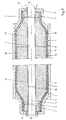
- FIG. 1 shows a torsion spring 1, which is used, for example, as a sectional door spring, d. H. for weight compensation on a sectional door can be used.
- the torsion spring 1 is made of spring steel wire 2 formed in a spiral around a spring axis 3 circumferential spring turns 4 is arranged.
- the torsion spring 1 has a smaller inner diameter at the spring ends 5 and 6 7 than in their central area 8.
- Connection elements matched while the inner diameter 7 of the Central area 8 on the specific stress of the torsion spring 1 is matched.
- the torsion spring 1 is here in one three-part die 9 to 11 arranged.
- the centerpiece 10 of the The die is cylindrical in shape and takes up the central area 8 with radial support of the spring turns 4 of the torsion spring 1 on.
- the head parts 9 and 11 of the die press the spring ends 5 and 6 of the torsion spring 1 together and seal the end faces 12 and 13 of the torsion spring 1 except for ice spray channels 14 in the Head part 9 and ventilation channels 15 in the head part 11.
- torsion spring arrangement For Production of a torsion spring arrangement is the first free Annulus 17 between the inner diameter 7 of the torsion spring 1 and an outer diameter 24 of the pipe section 16 through the Injection channels 14 sprayed with a substance 19, which in the annular space 17 forms an elastic foam.
- the foam puts on the spring turns 4. But it does not stick with the spring steel wire 2 because of this before ejecting the Torsion spring 1 on the inside of the torsion spring 1 with a Release agent and lubricant was treated.
- the annulus 17 is foamed, the air contained in it escapes the ventilation channels 15. Foaming is finished when the Foam emerges from the ventilation channels 15.
- the torsion spring assembly with the torsion spring 1 and that of the tube section 16 and the elastic jacket 18th formed carrier sleeve are removed from the die 9 to 11. Now there is no danger that the carrier sleeve both anchored positively and positively in the torsion spring 1 is, falls out of the torsion spring 1.
- the torsion spring 1 on torsion changes its inner diameter 7, and due to their torsion, the individual twist Spring turns 4 against each other.
- the change in diameter of the Inner diameter 7 is due to elastic deformation of the jacket 18 compensated, the jacket 18 with its surface 20th constantly rests on the spring turns 4 of the spring steel wire 2.
- the tubular sleeve 21 is made of elastic deformable material.
- the tubular Cover 21 via the injection channels 14 of the head piece 9, which here is shown as the only one from the die 9 to 11, where the tubular shell from the inside to the Torsion spring 1 creates.
- the spraying out of the casing 21 substance 22 used forms a hard foam. in the The result is the torsion spring arrangement 22 according to FIG. 3 receive.
- This consists of the torsion spring 1 and one Carrier sleeve viewed from the inside from the pipe section 16, then a hard jacket 23 around the pipe section 16 and ultimately from the elastic jacket 18 around the hard jacket 23 around, the hard shell 23 from the substance 24 and the elastic jacket 18 is formed by the sleeve 21.
- the surface 20 of the shell 21 or the elastic Jacket 18 in turn be designed so that the lowest possible Sliding friction forces between it and the spring steel wire 2 occur.
- FIG 4 Another embodiment of the torsion spring assembly 22 is shown in Figure 4. This differs from that according to Figure 3 in that a hard core of the carrier sleeve for the torsion spring only the hard shell 23 but not the Pipe section 16 includes. Rather, the pipe section 16 is here been pulled out. That means he only has part of the matrix served to eject the torsion spring 1.
- the Pipe section of course, no continuous central opening whether they have a recess in the center area at all. He can also be a solid rod.
- the new torsion spring arrangement and the process for its manufacture can also be applied to cylindrical torsion springs 1, the annulus in turn within the torsion spring what is cylindrical and thus geometrically simpler can translate into cost advantages.
- a substance to form an elastic Jacket 18 and a substance for foaming the annular space of can be introduced inside.
- it can be act only one substance.
- Substances can both substances in the annular space 17th be foamed. But it is also possible to use only one substance to foam, this corresponds to the embodiment according to Figure 2.
Landscapes
- Engineering & Computer Science (AREA)
- General Engineering & Computer Science (AREA)
- Mechanical Engineering (AREA)
- Springs (AREA)
Abstract
Description
Die Erfindung bezieht sich auf ein Verfahren zur Herstellung einer Torsionsfederanordnung mit einer langgestreckten, aus Federstahldraht gewickelten oder gewundenen und eine hohe Windungszahl aufweisenden Torsionsfeder und einer in dem freien Querschnitt der Torsionsfeder angeordneten Trägerhülse für die Torsionsfeder zur Unterdrückung von Verwerfungen der auf Torsion beanspruchten Torsionsfeder, wobei ein Rohrabschnitt in die Torsionsfeder eingebracht wird. Weiterhin bezieht sich die Erfindung auf eine Torsionsfederanordnung mit einer langgestreckten, aus Federstahldraht gewickelten oder gewundenen und eine hohe Windungszahl aufweisenden Torsionsfeder und eine in dem freien Querschnitt der Torsionsfeder angeordneten Trägerhülse für die Torsionsfeder zur Unterdrückung von Verwerfungen der auf Torsion beanspruchten Torsionsfeder, wobei die Trägerhülse einen harten Hülsenkern aufweist.The invention relates to a method of manufacture a torsion spring arrangement with an elongated, from Spring steel wire wound or coiled and high Number of turns torsion spring and one in the free Cross section of the torsion spring arranged support sleeve for the Torsion spring to suppress warping on torsion claimed torsion spring, wherein a pipe section in the Torsion spring is introduced. Furthermore, the Invention on a torsion spring arrangement with an elongated, made of spring steel wire or wound and a high number of turns torsion spring and an in the free cross section of the torsion spring arranged support sleeve for the torsion spring to suppress warpage the torsion spring stressed on torsion, the carrier sleeve has a hard core.
Torsionsfedern werden beispielsweise zum Ausgleich von Gewichtskräften bei Sektionaltoren verwendet, die im zunehmenden Maße als Garagen- und Industrietore Verwendung finden.Torsion springs are used, for example, to balance weight forces used in sectional gates, which are increasing find use as garage and industrial doors.
Die Grundform von gewickelten oder gewundenen Torsionsfedern ist zylindrisch. Solche Torsionsfedern können auf einen Rohrabschnitt als Trägerhülse aufgeschoben werden, um Verwerfungen der auf Torsion beanspruchten Torsionsfeder zu unterdrücken. Allerdings ergibt sich allein durch das Einschieben des Rohrabschnitts in die Torsionsfeder noch keine einfach zu handhabende Baueinheit, da der Rohrabschnitt ohne zusätzliche Sicherungsmaßnahmen bei Handhabungen der Torsionsfederanordnung vor ihrer Installation leicht herausfällt.The basic form of wound or coiled torsion springs is cylindrical. Such torsion springs can on a pipe section be pushed on as a carrier sleeve in order to warp the suppress torsion spring stressed on torsion. However, this results solely from the insertion of the pipe section not yet easy to use in the torsion spring Structural unit, since the pipe section without additional security measures when handling the torsion spring arrangement before it Installation easily falls out.
Aus der EP 965 399 A2 ist es bekannt, beim Winden einer spiralförmigen Torsionsfeder die Federenden mit kleinerem Innnendurchmesser zu winden als den dazwischen liegenden Hauptbereich der Torsionsfeder. Dies ermöglicht es, bei spiralförmigen Torsionsfedern für unterschiedliche Beanspruchungen die Federenden jeweils mit gleichem Innendurchmesser zu winden, so daß gleiche Befestigungselemente zur Anwendung kommen können und beispielsweise auch eine einheitliche Länge der Torsionsfedern unabhängig von ihrer Beanspruchung realisierbar ist. Die Abstimmung der Torsionsfedern auf die jeweilige Beanspruchung erfolgt über den zwischen den Federenden liegenden Hauptbereich der Torsionsfedern. Bei solchen Torsionsfedern mit konisch eingezogenen Federenden ist es aber schwierig, auch den Hauptbereich zwischen den Federenden mit einer Trägerhülse radial abzustützen. In der EP 965 399 A2 wird hierzu vorgeschlagen, bereits beim Winden der spiralförmigen Torsionsfeder einen Stützkörper in Form eines Rohrabschnitts in den Hauptbereich der Torsionsfeder einzubringen. Nach dem Winden des zweiten Federendes ist dieser Stützkörper durch die beiden konisch eingezogenen Federenden in der Torsionsfeder fixiert. Es stellt sich jedoch als aufwendig heraus, den Stützkörper tatsächlich bereits während des Windens der Torsionsfeder einzubringen. Darüberhinaus muß ein zweiter Rohrabschnitt nach dem Winden der Torsionsfeder durch die Federenden und durch den ersten Rohrabschnitt hindurch in die Torsionsfeder eingebracht werden, um auch die Federenden abzustützen.From EP 965 399 A2 it is known to wind a spiral Torsion spring the spring ends with a smaller inner diameter as the main area in between Torsion spring. This makes it possible to use spiral torsion springs the spring ends for different loads to wind each with the same inner diameter, so that the same Fasteners can be used and for example also a uniform length of the torsion springs independently is realizable from their stress. The vote of Torsion springs on the respective load are made via the main area of the torsion springs located between the spring ends. With such torsion springs with conically retracted Spring ends but it is difficult to even the main area between radially support the spring ends with a carrier sleeve. In the EP 965 399 A2 is proposed for this purpose, even when winding the spiral torsion spring a support body in the form of a Pipe section into the main area of the torsion spring. After winding the second spring end, this is the support body through the two conical spring ends in the Torsion spring fixed. However, it turns out to be expensive out, the support body actually already during the winch the torsion spring. In addition, a second Pipe section after winding the torsion spring through the Spring ends and through the first pipe section into the Torsion spring can be introduced to the spring ends to support.
Dabei sollte dieser zweite Rohrabschnitt möglichst wenig Spiel zu dem ersten Rohrabschnitt aufweisen. Dies behindert aber sein einfaches Einbringen in die Torsionsfeder mit dem ersten Rohrabschnitt.This second pipe section should have as little play as possible to the first pipe section. But this hinders it easy insertion into the torsion spring with the first pipe section.
In jedem Fall ist der Außendurchmesser einer harten Trägerhülse für die Torsionsfeder so auf den Innendurchmesser der Torsionsfeder abzustimmen, daß der minimale Innendurchmesser, den die Torsionsfeder in ihrer Verwendung erreicht, nicht kleiner ist als der Außendurchmesser der Trägerhülse, damit die Trägerhülse die Funktion der Torsionsfeder nicht beeinträchtigt. Dies bedeutet aber umgekehrt, daß zwischen dem Innendurchmesser der Torsionsfeder und dem Außendurchmesser der Trägerhülse normalerweise immer ein Freiraum verbleibt. Mit anderen Worten hat die Torsionsfeder Spiel auf der Trägerhülse. Dies kann zu unerwünschten Geräuschentwicklungen und unerwünschtem Verwerfungen im Bereich der Torsionsfederanordnung führen.In any case, the outside diameter is a hard carrier sleeve for the torsion spring so on the inner diameter of the torsion spring to vote that the minimum inside diameter that the Torsion spring achieved in its use, is not smaller than the outside diameter of the carrier sleeve, so the carrier sleeve does not affect the function of the torsion spring. This conversely means that between the inside diameter of the Torsion spring and the outer diameter of the carrier sleeve normally there is always a free space. In other words, it has Torsion spring play on the carrier sleeve. This can be undesirable Noises and unwanted distortions lead in the area of the torsion spring arrangement.
Der Erfindung liegt die Aufgabe zugrunde, ein Verfahren der eingangs beschriebenen Art zur Herstellung einer Torsionsfederanordnung aufzuzeigen, bei dem die aus dem Stand der Technik bekannten Nachteile vermieden werden. Weiterhin soll eine Torsionsfederanordnung der eingangs beschriebenen Art aufgezeigt werden, die nach dem neuen Verfahren herstellbar ist und ihrerseits die Nachteile des Stands der Technik beseitigt.The invention has for its object a method of type described above for producing a torsion spring arrangement to demonstrate in which the state of the art known disadvantages can be avoided. Furthermore, a Torsion spring arrangement of the type described above is shown that can be produced using the new method and in turn eliminates the disadvantages of the prior art.
Erfindungsgemäß wird diese Aufgabe bei einem Verfahren der eingangs beschriebenen Art dadurch gelöst, daß der Außendurchmesser des Rohrabschnitts zumindest über einen Teilbereich seiner Längserstreckung so auf den Innendurchmesser der Torsionsfeder abgestimmt wird, daß der minimale Innendurchmesser, den die Torsionsfeder in ihrer Verwendung erreicht, größer ist als der Außendurchmesser des Rohrabschnitts, daß der Rohrabschnitt coaxial in der Torsionsfeder angeordnet wird und daß in einen freien Ringraum zwischen der Torsionsfeder und dem darin coaxial angeordneten Rohrabschnitt mindestens eine Substanz eingebracht wird, die einen elastisch verformbaren Mantel um den Rohrabschnitt herum ausbildet, welcher von innen an der Torsionsfeder anliegt.According to the invention, this object is achieved in a method of the beginning described type solved in that the outer diameter of the pipe section at least over a portion of it Longitudinal extension on the inner diameter of the torsion spring that the minimum inside diameter that the Torsion spring achieved in their use is greater than that Outer diameter of the pipe section that the pipe section is arranged coaxially in the torsion spring and that in a free annular space between the torsion spring and the coaxial therein arranged pipe section introduced at least one substance is that an elastically deformable jacket around the pipe section around, which from the inside on the torsion spring is present.
Im Vergleich zum Stand der Technik geht das neue Verfahren bewußt von einem in Bezug auf seinen Außendurchmesser untermaßigen Rohrabschnitt aus. Das heißt, zwischen dem Außendurchmesser des Rohrabschnitts und dem Innendurchmesser der Torsionsfeder verbleibt immer ein Raum, der gemäß dem neuen Verfahren jedoch nicht freigelassen wird. Vielmehr wird dieser Raum durch die coaxiale Anordnung des Rohrabschnitts in der Torsionsfeder zu einem möglichst rotationssymmetrischen Ringraum gemacht. Dann wird dieser Ringraum zwischen der Torsionsfeder und dem darin coaxial angeordneten Rohrabschnitt ausgefüllt. Dies geschieht unter Verwendung mindestens einer Substanz, die einen elastisch verformbaren Mantel um den Rohrabschnitt herum ausbildet, an dem sich die Torsionsfeder in radialer Richtung elastisch abstützt. Das heißt, bei Torsionsfederanordnungen, die nach dem neuen Verfahren hergestellt wurden, liegt die Torsionsfeder bei möglichst allen Innendurchmessern, den die Torsionsfeder in ihrer Verwendung erreicht, umlaufend an dem elastisch verformbaren Mantel an. Hierdurch wird nicht nur die Relativlage der Torsionsfeder zu der Trägerhülse optimal definiert, es werden auch Schwingungen des Federdrahts der Torsionsfeder gedämpft. Im Ergebnis ergeben sich aufgrund der Herstellung der Torsionsfederanordnung nach dem neuen Verfahren deutlich weniger ausgeprägte Verwerfungen und eine geringere Geräuschentwicklung.Compared to the state of the art, the new method works conscious of one undersized in terms of its outside diameter Pipe section. That is, between the outside diameter of the pipe section and the inner diameter of the torsion spring there is always a room, but according to the new procedure is not released. Rather, this space is created by the coaxial arrangement of the pipe section in the torsion spring an annulus that is as rotationally symmetrical as possible. Then this annular space between the torsion spring and the inside Filled coaxial pipe section. this happens using at least one substance that is elastic deformable jacket forms around the pipe section on which the torsion spring is supported elastically in the radial direction. That is, in the case of torsion spring arrangements which are based on the new method were produced, the torsion spring is as possible all inner diameters that the torsion spring uses in its use reached, all around on the elastically deformable jacket on. As a result, not only the relative position of the torsion spring to the carrier sleeve optimally defined, there are also vibrations of the spring wire of the torsion spring damped. As a result result from the manufacture of the torsion spring arrangement warps significantly less pronounced according to the new process and less noise.
Bei dem neuen Verfahren kann die Torsionsfeder vor dem Einbringen der Substanz in den Ringraum soweit zusammengedrückt werden, daß benachbarte Federwindungen aus dem Federstahldraht dichtend aneinanderliegen. Damit wird in aller Regel eine solche Abdichtung der Torsionsfeder in radialer Richtung erreicht, wie sie für die Durchführung des neuen Verfahrens notwendig ist. Das notwendige Maß der Abdichtung hängt aber stark von der jeweiligen Ausführungsform des neuen Verfahrens ab.With the new method, the torsion spring can be inserted the substance is compressed into the annular space that adjacent spring turns from the spring steel wire sealing lie together. As a rule, such a seal the torsion spring reaches in the radial direction as they is necessary for the implementation of the new procedure. The the necessary degree of sealing depends strongly on the respective Embodiment of the new method.
So kann vor dem Ausbilden des elastisch verformbaren, von innen an der Torsionsfeder anliegenden Mantels eine schlauchförmige Hülle in den Ringraum eingebracht werden. Diese schlauchförmige Hülle kann dann in dem Ringraum soweit aufgeweitet werden, daß sie sich von innen an die Torsionsfeder anlegt. Dies ist beispielsweise durch Aufblasen der schlauchförmigen Hülle möglich. Die schlauchförmige Hülle kann dabei nur die Oberfläche des elastischen Mantels oder aber Teile des elastischen Mantels oder gar den gesamten elastischen Mantel ausbilden.So before forming the elastically deformable, from the inside a tubular jacket attached to the torsion spring Sheath can be introduced into the annulus. This tubular one Envelope can then be expanded in the annular space to the extent that it attaches itself to the torsion spring from the inside. For example, this is possible by inflating the tubular casing. The tubular shell can only the surface of the elastic jacket or parts of the elastic jacket or even form the entire elastic jacket.
Gerade im letzten Fall ist bei dem neuen Verfahren der dann verbleibende Ringraum zwischen der schlauchförmigen Hülle und dem Rohrabschnitt mit einer weiteren Substanz auszufüllen, die einen harten Mantel um den Rohrabschnitt ausbildet, um den elastischen Mantel nach innen abzustützen.The latter is the case with the new procedure remaining annular space between the tubular casing and fill the pipe section with another substance, the forms a hard jacket around the pipe section around which support the elastic jacket on the inside.
Dies ist eine Variante des allgemeineren Prinzips, welches bei dem neuen Verfahren zur Anwendung kommen kann, wonach zwei verschiedene Substanzen in den Ringraum eingebracht werden, wobei die eine den elastisch verformbaren Mantel und die andere einen harten Mantel zwischen dem Rohrabschnitt und dem elastisch verformbaren Mantel ausbildet. Zum Abschluß des neuen Verfahrens in dieser Ausführungsform ist es dann möglich, den Rohrabschnitt aus dem harten Mantel zu entfernen, so daß die Trägerhülse der Torsionsfederanordnung nur aus dem harten Mantel und dem elastischen Mantel besteht, während der Rohrabschnitt nur als Innenmatrize gedient hat.This is a variant of the more general principle, which at the new procedure can be applied, according to which two various substances are introduced into the annular space, one being the elastically deformable jacket and the other a hard jacket between the pipe section and the elastic deformable sheath. At the end of the new procedure in this embodiment it is then possible to use the pipe section to remove from the hard coat, so that the carrier sleeve Torsion spring arrangement only from the hard jacket and the elastic Jacket exists, while the pipe section only as an inner matrix served.
Sofern eine der Substanzen nicht als oder auf einer schlauchförmigen Hülle in den Ringraum zwischen der Torsionsfeder und dem darin coaxial angeordneten Rohrabschnitt eingebracht wird, ist es bei dem neuen Verfahren bevorzugt, die Substanz in einer verdichteten Vorform in den Ringraum einzuspritzen und dann in dem Ringraum zu expandieren. Zur Ausbildung eines harten Mantels nach dieser Verfahrensvariante könnte beispielsweise auf üblichen Montageschaum, wie er zum Einbauen von Fenstern und Türen verwendet wird, zurückgegriffen werden. Es sind aber auch Substanzen für den elastischen Mantel in den Ringraum einspritzbar, wobei auf den in dieser Beziehung umfangreichen Stand der Technik zurückgegriffen werden kann.Unless one of the substances as or on a tubular Envelope in the annulus between the torsion spring and the pipe section arranged coaxially therein is introduced, it is preferred in the new process to use the substance in a inject the preform into the annulus and then into it to expand the annulus. For the formation of a hard coat this method variant could, for example, be based on conventional methods Assembly foam, such as that used for installing windows and doors is used. But they are also substances can be injected into the annular space for the elastic jacket, the extensive state of the art in this regard can be used.
Bei ihrer Verwendung, d. h. ihrer Beanspruchung auf Torsion, ändert die Torsionsfeder nicht nur ihren Innendurchmesser. Es tritt auch eine Torsion der gesamten Torsionsfeder verbunden mit einer Verdrehung der einzelnen Federwindungen des Federstahldrahts gegeneinander auf. Diese Bewegungen dürfen bei der Torsionsfederanordnung, die nach dem neuen Verfahren hergestellt wird, nicht behindert werden. Dem kann dadurch Rechnung getragen werden, daß eine schlauchförmige Hülle zur Ausbildung der Oberfläche des elastischen Mantels in dem Ringraum so ausgebildet ist, daß Gleitreibungskräfte zwischen der Trägerhülse und der Torsionsfeder minimiert werden. Mit demselben Ziel kann die Torsionsfeder vor dem Einbringen der Substanz, die den elastisch verformbaren Mantel um den Rohrabschnitt ausbildet, innen mit einem Trenn- und/oder Schmiermittel beschichtet werden. Das Trennmittel hat die Funktion, daß grundsätzlich keine Verklebung zwischen dem elastischen Mantel und der Torsionsfeder erfolgt. Das Schmiermittel setzt die Gleitreibung zwischen der Torsionsfeder und dem elastischen Mantel herab. Eine geringe Gleitreibung ist auch wichtig, um einen Abrieb des elastischen Mantels zu verhindern.When used, i. H. their stress on torsion, the torsion spring not only changes its inner diameter. It there is also a torsion associated with the entire torsion spring a twist of the individual spring turns of the spring steel wire against each other. With the torsion spring arrangement, these movements may which are manufactured using the new process will not be hindered. This can be taken into account be that a tubular sheath to form the surface of the elastic jacket formed in the annular space is that sliding friction forces between the carrier sleeve and the Torsion spring can be minimized. With the same goal Torsion spring before introducing the substance that is elastic deformable jacket forms around the pipe section, inside with a release agent and / or lubricant are coated. The Release agent has the function that basically no gluing between the elastic jacket and the torsion spring. The lubricant sets the sliding friction between the torsion spring and the elastic jacket. A little sliding friction is also important to abrasion of the elastic jacket to prevent.
Zur praktischen Durchführung des neuen Verfahrens kann die Torsionsfeder zum Einbringen aller noch gestaltloser Substanzen in den Ringraum in eine Matrize eingebracht werden, die den Rohrabschnitt coaxial in der Torsionsfeder hält und die Federenden der Torsionsfeder abdichtet. Das Einbringen einer schlauchförmigen Hülle in den Ringraum kann vorher, beispielsweise zusammen mit dem Rohrabschnitt erfolgen.For the practical implementation of the new procedure, the Torsion spring for the introduction of all still formless substances are introduced into the annulus in a die that the Pipe section holds coaxially in the torsion spring and the spring ends seals the torsion spring. Introducing a tubular Sheath in the annulus can be used beforehand, for example done together with the pipe section.
Bei einer Torsionsfederanordnung der eingangs beschriebenen Art wird die erfindungsgemäße Aufgabe dadurch gelöst, daß der Außendurchmesser des harten Hülsenkerns zumindest über einen Teilbereich seiner Längserstreckung so auf den Innendurchmesser der Torsionsfeder abgestimmt ist, daß der minimale Innendurchmesser, den die Torsionsfeder in ihrer Verwendung erreicht, größer ist als der Außendurchmesser des Hülsenkerns und daß in einem Ringraum zwischen der Torsionsfeder und dem darin coaxial angeordneten Hülsenkern ein elastisch verformbarer Mantel um den Hülsenkern angordnet ist, welcher von innen an der Torsionsfeder anliegt.In a torsion spring arrangement of the type described in the introduction the object of the invention is achieved in that the Outside diameter of the hard sleeve core at least one Part of its longitudinal extent on the inside diameter the torsion spring is adjusted so that the minimum inside diameter, which the torsion spring achieves in use, is larger than the outer diameter of the core and that in an annular space between the torsion spring and the coaxial therein arranged sleeve core an elastically deformable jacket around the The sleeve core is arranged, which is on the inside of the torsion spring is present.
Wie bereits im Zusammenhang mit dem neuen Verfahren erläutert, sorgt der elastisch verformbare Mantel zum einen für eine definierte Relativlage der Torsionsfeder zu dem untermaßigen Hülsenkern. Zum anderen wird auch eine Dämpfung von Schwingungen des Federstahldrahts erreicht.As already explained in connection with the new process, on the one hand, the elastically deformable jacket ensures one defined relative position of the torsion spring to the undersized Core. On the other hand there is also a damping of vibrations of the spring steel wire reached.
Besonders bevorzugt sind Ausführungsformen der neuen Torsionsfederanordnung, bei denen die Torsionsfeder an ihren Federenden jeweils einen abnehmenden Innendurchmesser aufweist, wobei der Außendurchmesser des harten Hülsenkerns an den Federenden der Torsionsfeder ebenfalls abnimmt. Dies bedeutet, daß der harte Hülsenkern nicht nur reibschlüssig über den elastischen Mantel sondern seinerseits formschlüssig in der Torsionsfeder fixiert ist. Dennoch kann er nach dem neuen Verfahren nach dem Fertigwinden oder -wickeln der Torsionsfeder in der Torsionsfeder angeordnet werden.Embodiments of the new torsion spring arrangement are particularly preferred, where the torsion spring at its spring ends each has a decreasing inner diameter, the Outside diameter of the hard sleeve core at the spring ends of the Torsion spring also decreases. This means that the hard one Sleeve core not only frictionally over the elastic jacket but in turn fixed positively in the torsion spring is. Nevertheless, he can use the new procedure after finishing finishing or winding the torsion spring in the torsion spring to be ordered.
In einer konkreten Ausführungsform der neuen Torsionsfederanordnung ist der Hülsenkern zumindest im Bereich seines Außendurchmessers aus einem Hartschaum und im Bereich des elastischen Mantels aus einem Weichschaum ausgebildet. Wenn der Rohrabschnitt nach dem Ausfüllen des Ringraums zwischen ihm und der Torsionsfeder wieder entfernt wird, kann auch der gesamte Hülsenkern aus dem Hartschaum bestehen.In a specific embodiment of the new torsion spring arrangement is the sleeve core at least in the area of its outer diameter from a rigid foam and in the area of elastic Coat formed from a soft foam. If the pipe section after filling the annulus between him and the Torsion spring is removed again, the entire Core consist of the rigid foam.
Die Erfindung wird im folgenden anhang von Ausführungsbeispielen näher erläutert und beschrieben. Dabei zeigt
Figur 1- eine in einer Ausspritzmatrize angeordnete Torsionsfeder bei der Herstellung der neuen Torsionsfederanordnung in einer erste Ausführungsfrom,
Figur 2- eine Torsionsfeder bei der Herstellung der Torsionsfederanordnung in einer zweiten Ausführungsform,
Figur 3- eine dritte Ausführungsform der Torsionsfeder und
Figur 4- eine vierte Ausführungsform der Torsionsfeder.
- Figure 1
- a torsion spring arranged in an ejection die during the manufacture of the new torsion spring arrangement in a first embodiment,
- Figure 2
- a torsion spring in the manufacture of the torsion spring arrangement in a second embodiment,
- Figure 3
- a third embodiment of the torsion spring and
- Figure 4
- a fourth embodiment of the torsion spring.
Figur 1 zeigt eine Torsionsfeder 1, die beispielsweise als Sektionaltorfeder,
d. h. zum Gewichtsausgleich bei einem Sektionaltor
verwendet werden kann. Die Torsionsfeder 1 ist aus Federstahldraht
2 ausgebildet, der in spiralförmig um eine Federachse
3 umlaufenden Federwindungen 4 angeordnet ist. Die Torsionsfeder
1 weist an den Federenden 5 und 6 einen kleineren Innendurchmesser
7 als in ihrem Zentralbereich 8 auf. Dabei ist der Innendurchmesser
7 der Federenden 5 und 6 auf hier nicht dargestellte
Anschlußelemente abgestimmt, während der Innendurchmesser 7 des
Zentralbereichs 8 auf die konkrete Beanspruchung der Torsionsfeder
1 abgestimmt ist. Die Torsionsfeder 1 ist hier in einer
dreiteiligen Matrize 9 bis 11 angeordnet. Das Mittelstück 10 der
Matrize ist zylindermantelförmig und nimmt den Zentralbereich 8
unter radialer Abstützung der Federwindungen 4 der Torsionsfeder
1 auf. Die Kopfteile 9 und 11 der Matrize drücken die Federenden
5 und 6 der Torsionsfeder 1 zusammen und dichten die Stirnseiten
12 und 13 der Torsionsfeder 1 bis auf Eispritzkanäle 14 in dem
Kopfteil 9 und Entlüftungskanäle 15 in dem Kopfteil 11 ab. Dabei
ist ein Rohrabschnitt 16 coaxial zu der Federachse 3 in der
Torsionsfeder 1 angeordnet, der bis in die Kopfteile 9 und 11
der Matrize hinein oder sogar durch diese hindurch ragt. Zur
Herstellung einer Torsionsfederanordnung wird der zunächst freie
Ringraum 17 zwischen dem Innendurchmesser 7 der Torsionsfeder 1
und einem Außendurchmesser 24 des Rohrabschnitts 16 durch die
Einspritzkanäle 14 mit einer Substanz 19 ausgespritzt, die in
dem Ringraum 17 einen elastischen Schaum ausbildet. Der Schaum
legt sich an die Federwindungen 4 an. Er verklebt aber nicht mit
dem Federstahldraht 2, weil dieser vor dem Ausspritzen der
Torsionsfeder 1 an der Innenseite der Torsionsfeder 1 mit einem
Trenn- und Schmiermittel behandelt wurde. Während der Ringraum
17 ausgeschäumt wird, entweicht die in ihm enthaltene Luft durch
die Entlüftungskanäle 15. Das Ausschäumen ist beendet, wenn der
Schaum aus den Entlüftungskanälen 15 austritt. Nachdem der
Schaum 18 so weit ausgehärtet ist, daß er zwar einen elastischen
aber ansich formstabilen Mantel 18 um den Rohrabschnitt 16 herum
ausbildet, kann die Torsionsfederanordnung mit der Torsionsfeder
1 und der aus dem Rohrabschnitt 16 und dem elastischen Mantel 18
gebildeten Trägerhülse aus der Matrize 9 bis 11 entformt werden.
Jetzt besteht keine Gefahr, daß die Trägerhülse die sowohl
kraft- als auch formschlüssig in der Torsionsfeder 1 verankert
ist, aus der Torsionsfeder 1 herausfällt. Bei der Beanspruchung
der Torsionsfeder 1 auf Torsion ändert sich ihr Innendurchmesser
7, und aufgrund ihrer Torsion verdrehen sich die einzelnen
Federwindungen 4 gegeneinander. Die Durchmesseränderung des
Innendurchmessers 7 wird durch elastische Verformung des Mantels
18 kompensiert, wobei der Mantel 18 mit seiner Oberfläche 20
ständig an den Federwindungen 4 des Federstahldrahts 2 anliegt.
Während der relativen Verdrehungen der Federwindungen 4 um die
Federachse 3 gleitet der Federstahldraht 2 über die Oberfläche
20 des elastischen Mantels 18 ab, wobei das Trenn- und Schmiermittel
die Reibung soweit reduziert, daß die Funktion der
Torsionsfeder 1 nicht nennenswert beeinträchtigt wird. Dies gilt
auch für den Einfluß der elastischen Verformung des Mantels 18
auf die Funktion der Torsionsfeder 1. Bei der Torsionsfederanordnung,
die gemäß Figur 1 hergestellt wurde, besteht keine
Gefahr von Verwerfungen der auf Torsion beanspruchten Torsionsfeder
1, da diese auf der Trägerhülse 16, 18 definiert geführt
wird. Darüberhinaus bewirkt die Ankopplung des elastischen Mantels
18 an die Torsionsfeder 1 eine Dämpfung von Schwingungen
des Federstahldrahts 2 und damit eine Unterdrückung von
Geräuschentwicklungen.FIG. 1 shows a
Gemäß Figur 2 wird eine Trägerhülse für die Torsionsfeder 1
innerhalb der Torsionsfeder 1 dadurch ausgebildet, daß auf dem
Rohrabschnitt 16, der coaxial zu der Federachse 3 in der Torsionsfeder
1 angeordnet wird, eine schlauchförmige Hülle 21 angeordnet
ist. Die schlauchförmige Hülle 21 besteht aus elastisch
verformbarem Material. Anschließend wird die schlauchförmige
Hülle 21 über die Einspritzkanäle 14 des Kopfstücks 9, das hier
als einziges von der Matrize 9 bis 11 dargestellt ist, ausgespritzt,
wobei sich die schlauchförmige Hülle von innen an die
Torsionsfeder 1 anlegt. Die dabei zum Ausspritzen der Hülle 21
verwendete Substanz 22 bildet einen harten Schaum aus. Im
Ergebnis wird so die Torsionsfederanordnung 22 gemäß Figur 3
erhalten. Diese besteht aus der Torsionsfeder 1 und einer
Trägerhülse, die von innen her betrachtet aus dem Rohrabschnitt
16, dann einem harten Mantel 23 um den Rohrabschnitt 16 und
letztlich aus dem elastischen Mantel 18 um den harten Mantel 23
herum besteht, wobei der harte Mantel 23 aus der Substanz 24 und
der elastische Mantel 18 von der Hülle 21 ausgebildet wird.
Dabei kann die Oberfläche 20 der Hülle 21 bzw. des elastischen
Mantels 18 ihrerseits so ausgebildet sein, daß möglichst geringe
Gleitreibungskräfte zwischen ihr und dem Federstahldraht 2
auftreten.According to FIG. 2, a carrier sleeve for the
Eine weitere Ausführungsform der Torsionsfederanordnung 22 ist
in Figur 4 gezeigt. Diese Unterscheidet sich von derjenigen
gemäß Figur 3 dadurch, daß ein harter Kern der Trägerhülse für
die Torsionsfeder nur den harten Mantel 23 aber nicht den
Rohrabschnitt 16 umfaßt. Vielmehr ist der Rohrabschnitt 16 hier
herausgezogen worden. Das heißt, er hat nur als Teil der Matrize
zum Ausspritzen der Torsionsfeder 1 gedient. Dabei muß der
Rohrabschnitt natürlich keine durchgehende zentrale Öffnung
obder überhaupt eine Ausnehmung im Zentrumsbereich aufweisen. Er
kann vielmehr auch ein massiver Stab sein.Another embodiment of the
Die neue Torsionsfederanordnung bzw. das Verfahren zu ihrer Herstellung
sind auch auf zylindrische Torsionsfedern 1 anwendbar,
wobei der Ringraum innerhalb der Torsionsfeder seinerseits
zylindrisch und damit geometrisch einfacher gestaltet ist, was
sich in Kostenvorteilen niederschlagen kann. In jedem Fall muß
zwischen dem Außendurchmesser 24 des Rohrabschnitts 16 und dem
Innendurchmesser 7 der Torsionsfeder 1 bei coaxialer Anordnung
des Rohrabschnitts 16 in der Torsionsfeder 1 der Ringraum 17
vorliegen, in den eine Substanz zur Ausbildung eines elastischen
Mantels 18 und eine Substanz zum Ausschäumen des Ringraums von
innen eingebracht werden können. Dabei kann es sich insgesamt um
nur eine Substanz handeln. Bei Verwendung von zwei unterschiedlichen
Substanzen können beide Substanzen in den Ringraum 17
eingeschäumt werden. Es ist aber auch möglich, nur eine Substanz
einzuschäumen, dies entspricht dem Ausführungsbeispiel gemäß
Figur 2. The new torsion spring arrangement and the process for its manufacture
can also be applied to cylindrical torsion springs 1,
the annulus in turn within the torsion spring
what is cylindrical and thus geometrically simpler
can translate into cost advantages. In any case
between the
- 1 -1 -
- TorsionsfederTorsion spring
- 2 -2 -
- FederstahldrahtSpring steel wire
- 3 -3 -
- FederachseSpring axle
- 4 -4 -
- FederwindungSpring turn
- 5 -5 -
- FederendeSpring end
- 6 -6 -
- FederendeSpring end
- 7 -7 -
- InnendurchmesserInside diameter
- 8 -8th -
- ZentralbereichCentral area
- 9 -9 -
- KopfteilHeadboard
- 10 -10 -
- MittelstückCenterpiece
- 11 -11 -
- KopfteilHeadboard
- 12 -12 -
- StirnseiteFace
- 13 -13 -
- StirnseiteFace
- 14 -14 -
- EinspritzkanalInjection channel
- 15 -15 -
- EntlüftungskanalVentilation duct
- 16 -16 -
- RohrabschnittPipe section
- 17 -17 -
- RingraumAnnulus
- 18 -18 -
- elastischer Mantelelastic coat
- 19 -19 -
- Substanzsubstance
- 20 -20 -
- Oberflächesurface
- 21 -21 -
- HülleCover
- 22 -22 -
- TorsionsfederanordnungTorsion spring arrangement
- 23 -23 -
- harter Mantelhard coat
- 24 -24 -
- Außendurchmesserouter diameter
Claims (10)
Priority Applications (1)
| Application Number | Priority Date | Filing Date | Title |
|---|---|---|---|
| EP00101993A EP1122000A1 (en) | 2000-02-02 | 2000-02-02 | Process for the manufacture of a torsion spring arrangement and torsion spring arrangement |
Applications Claiming Priority (1)
| Application Number | Priority Date | Filing Date | Title |
|---|---|---|---|
| EP00101993A EP1122000A1 (en) | 2000-02-02 | 2000-02-02 | Process for the manufacture of a torsion spring arrangement and torsion spring arrangement |
Publications (1)
| Publication Number | Publication Date |
|---|---|
| EP1122000A1 true EP1122000A1 (en) | 2001-08-08 |
Family
ID=8167746
Family Applications (1)
| Application Number | Title | Priority Date | Filing Date |
|---|---|---|---|
| EP00101993A Withdrawn EP1122000A1 (en) | 2000-02-02 | 2000-02-02 | Process for the manufacture of a torsion spring arrangement and torsion spring arrangement |
Country Status (1)
| Country | Link |
|---|---|
| EP (1) | EP1122000A1 (en) |
Citations (4)
| Publication number | Priority date | Publication date | Assignee | Title |
|---|---|---|---|---|
| DE1041816B (en) * | 1956-11-21 | 1958-10-23 | Mecano Bundy Ges Mit Beschraen | Spring hangers for leaf springs, especially for motor vehicles |
| US3861661A (en) * | 1972-09-21 | 1975-01-21 | Nissan Motor | Compression spring assembly |
| JPS5794142A (en) * | 1980-12-01 | 1982-06-11 | Nhk Spring Co Ltd | Car suspension device |
| EP0965399A2 (en) * | 1998-06-18 | 1999-12-22 | Société Alsacienne pour la Transformation de l'Acier S.a.r.l. | Process for the manufacture of a wire spring from a hard metal wire having a round section |
-
2000
- 2000-02-02 EP EP00101993A patent/EP1122000A1/en not_active Withdrawn
Patent Citations (4)
| Publication number | Priority date | Publication date | Assignee | Title |
|---|---|---|---|---|
| DE1041816B (en) * | 1956-11-21 | 1958-10-23 | Mecano Bundy Ges Mit Beschraen | Spring hangers for leaf springs, especially for motor vehicles |
| US3861661A (en) * | 1972-09-21 | 1975-01-21 | Nissan Motor | Compression spring assembly |
| JPS5794142A (en) * | 1980-12-01 | 1982-06-11 | Nhk Spring Co Ltd | Car suspension device |
| EP0965399A2 (en) * | 1998-06-18 | 1999-12-22 | Société Alsacienne pour la Transformation de l'Acier S.a.r.l. | Process for the manufacture of a wire spring from a hard metal wire having a round section |
Non-Patent Citations (1)
| Title |
|---|
| PATENT ABSTRACTS OF JAPAN vol. 006, no. 187 (M - 158) 25 September 1982 (1982-09-25) * |
Similar Documents
| Publication | Publication Date | Title |
|---|---|---|
| DE69016707T2 (en) | Dynamic damper. | |
| DE69300947T2 (en) | Built camshaft. | |
| WO2019115436A1 (en) | Telescopic rail | |
| EP0324499A1 (en) | Method for producing a composite shaft | |
| DE102008007153A1 (en) | Length adjustable shaft | |
| DE3701887A1 (en) | INTERMEDIATE BEARING FOR THE DRIVE SHAFT OF MOTOR VEHICLES | |
| DE69512608T2 (en) | ELASTIC BEARING WITH AT LEAST TWO CYLINDRICAL BUSHINGS, BUSHINGS FOR SUCH A BEARING AND FABRICATION PROCESS OF THE BEARING BY MEANS OF SUCH A BUSHING | |
| EP0137958A2 (en) | Propulsive charge and method for manufacturing | |
| EP1122000A1 (en) | Process for the manufacture of a torsion spring arrangement and torsion spring arrangement | |
| DE4233896C2 (en) | piston | |
| DE10337918A1 (en) | Homocinetic joint in the form of a twin-ball joint comprises an outer joint part provided with outer ball tracks, and an inner joint part provided with inner ball tracks | |
| EP0472950B1 (en) | Elastic coupling | |
| DE3010690A1 (en) | Hydraulic suspension damper for vehicle - has axial grooves in stop ring steps working with additional slotted damping rings | |
| DE60021758T2 (en) | ARRANGEMENT WITH A SLEEVE INSTALLED ON A METALLIC CYLINDER | |
| DE10206317B4 (en) | Coil spring arrangement | |
| DE60021764T2 (en) | DEVICE AND METHOD FOR MOUNTING THE ROTOR OF A HERMETICALLY CLOSED COMPRESSOR | |
| DE60108632T2 (en) | DEVICE AND METHOD FOR INSERTING INSERTS IN BLAST-MOLDED PLASTIC ELEMENTS | |
| DE3700805C2 (en) | ||
| DE2701295C2 (en) | ||
| DE2731333C2 (en) | ||
| DE102016214206A1 (en) | Device for eradicating vibration resonances | |
| DE102019205667B4 (en) | Compression spring for insertion in a spindle drive for an adjusting element of a vehicle door | |
| DE102021108998A1 (en) | Deep groove ball bearing and a method for manufacturing a deep groove ball bearing | |
| EP0855233B1 (en) | Method for the manufacture of vibration-damped rolls and set of rolls | |
| DE3020497C2 (en) | Sub-circular rotor |
Legal Events
| Date | Code | Title | Description |
|---|---|---|---|
| PUAI | Public reference made under article 153(3) epc to a published international application that has entered the european phase |
Free format text: ORIGINAL CODE: 0009012 |
|
| AK | Designated contracting states |
Kind code of ref document: A1 Designated state(s): AT BE CH CY DE DK ES FI FR GB GR IE IT LI LU MC NL PT SE |
|
| AX | Request for extension of the european patent |
Free format text: AL;LT;LV;MK;RO;SI |
|
| AKX | Designation fees paid | ||
| REG | Reference to a national code |
Ref country code: DE Ref legal event code: 8566 |
|
| STAA | Information on the status of an ep patent application or granted ep patent |
Free format text: STATUS: THE APPLICATION IS DEEMED TO BE WITHDRAWN |
|
| 18D | Application deemed to be withdrawn |
Effective date: 20020209 |