EP1122000A1 - Procédé de fabrication d'un arrangement de ressort à torsion et arrangement de ressort à torsion - Google Patents
Procédé de fabrication d'un arrangement de ressort à torsion et arrangement de ressort à torsion Download PDFInfo
- Publication number
- EP1122000A1 EP1122000A1 EP00101993A EP00101993A EP1122000A1 EP 1122000 A1 EP1122000 A1 EP 1122000A1 EP 00101993 A EP00101993 A EP 00101993A EP 00101993 A EP00101993 A EP 00101993A EP 1122000 A1 EP1122000 A1 EP 1122000A1
- Authority
- EP
- European Patent Office
- Prior art keywords
- torsion spring
- spring
- torsion
- annular space
- pipe section
- Prior art date
- Legal status (The legal status is an assumption and is not a legal conclusion. Google has not performed a legal analysis and makes no representation as to the accuracy of the status listed.)
- Withdrawn
Links
- 238000000034 method Methods 0.000 title claims abstract description 30
- 238000004519 manufacturing process Methods 0.000 title claims description 8
- 239000000126 substance Substances 0.000 claims description 26
- 229910000639 Spring steel Inorganic materials 0.000 claims description 15
- 239000006260 foam Substances 0.000 claims description 12
- 239000000314 lubricant Substances 0.000 claims description 5
- 230000007423 decrease Effects 0.000 claims description 2
- 230000003247 decreasing effect Effects 0.000 claims description 2
- 239000000463 material Substances 0.000 abstract description 2
- 238000005253 cladding Methods 0.000 abstract 2
- 238000009423 ventilation Methods 0.000 description 4
- 238000004804 winding Methods 0.000 description 4
- 239000003795 chemical substances by application Substances 0.000 description 3
- 238000002347 injection Methods 0.000 description 3
- 239000007924 injection Substances 0.000 description 3
- 238000013016 damping Methods 0.000 description 2
- 230000005489 elastic deformation Effects 0.000 description 2
- 238000005187 foaming Methods 0.000 description 2
- 238000003780 insertion Methods 0.000 description 2
- 230000037431 insertion Effects 0.000 description 2
- 239000011159 matrix material Substances 0.000 description 2
- 238000007789 sealing Methods 0.000 description 2
- 238000005299 abrasion Methods 0.000 description 1
- 238000004026 adhesive bonding Methods 0.000 description 1
- 230000015572 biosynthetic process Effects 0.000 description 1
- 238000007796 conventional method Methods 0.000 description 1
- 230000008878 coupling Effects 0.000 description 1
- 238000010168 coupling process Methods 0.000 description 1
- 238000005859 coupling reaction Methods 0.000 description 1
- 238000011161 development Methods 0.000 description 1
- 230000018109 developmental process Effects 0.000 description 1
- 238000009434 installation Methods 0.000 description 1
- 239000007787 solid Substances 0.000 description 1
- 239000007921 spray Substances 0.000 description 1
- 238000005507 spraying Methods 0.000 description 1
- 230000001629 suppression Effects 0.000 description 1
Images


Classifications
-
- B—PERFORMING OPERATIONS; TRANSPORTING
- B21—MECHANICAL METAL-WORKING WITHOUT ESSENTIALLY REMOVING MATERIAL; PUNCHING METAL
- B21F—WORKING OR PROCESSING OF METAL WIRE
- B21F35/00—Making springs from wire
- B21F35/02—Bending or deforming ends of coil springs to special shape
-
- F—MECHANICAL ENGINEERING; LIGHTING; HEATING; WEAPONS; BLASTING
- F16—ENGINEERING ELEMENTS AND UNITS; GENERAL MEASURES FOR PRODUCING AND MAINTAINING EFFECTIVE FUNCTIONING OF MACHINES OR INSTALLATIONS; THERMAL INSULATION IN GENERAL
- F16F—SPRINGS; SHOCK-ABSORBERS; MEANS FOR DAMPING VIBRATION
- F16F1/00—Springs
- F16F1/02—Springs made of steel or other material having low internal friction; Wound, torsion, leaf, cup, ring or the like springs, the material of the spring not being relevant
- F16F1/04—Wound springs
- F16F1/12—Attachments or mountings
- F16F1/127—Attachments or mountings allowing rotation about axis of spring
-
- F—MECHANICAL ENGINEERING; LIGHTING; HEATING; WEAPONS; BLASTING
- F16—ENGINEERING ELEMENTS AND UNITS; GENERAL MEASURES FOR PRODUCING AND MAINTAINING EFFECTIVE FUNCTIONING OF MACHINES OR INSTALLATIONS; THERMAL INSULATION IN GENERAL
- F16F—SPRINGS; SHOCK-ABSORBERS; MEANS FOR DAMPING VIBRATION
- F16F1/00—Springs
- F16F1/02—Springs made of steel or other material having low internal friction; Wound, torsion, leaf, cup, ring or the like springs, the material of the spring not being relevant
- F16F1/14—Torsion springs consisting of bars or tubes
-
- F—MECHANICAL ENGINEERING; LIGHTING; HEATING; WEAPONS; BLASTING
- F16—ENGINEERING ELEMENTS AND UNITS; GENERAL MEASURES FOR PRODUCING AND MAINTAINING EFFECTIVE FUNCTIONING OF MACHINES OR INSTALLATIONS; THERMAL INSULATION IN GENERAL
- F16F—SPRINGS; SHOCK-ABSORBERS; MEANS FOR DAMPING VIBRATION
- F16F3/00—Spring units consisting of several springs, e.g. for obtaining a desired spring characteristic
Definitions
- the invention relates to a method of manufacture a torsion spring arrangement with an elongated, from Spring steel wire wound or coiled and high Number of turns torsion spring and one in the free Cross section of the torsion spring arranged support sleeve for the Torsion spring to suppress warping on torsion claimed torsion spring, wherein a pipe section in the Torsion spring is introduced.
- the Invention on a torsion spring arrangement with an elongated, made of spring steel wire or wound and a high number of turns torsion spring and an in the free cross section of the torsion spring arranged support sleeve for the torsion spring to suppress warpage the torsion spring stressed on torsion, the carrier sleeve has a hard core.
- Torsion springs are used, for example, to balance weight forces used in sectional gates, which are increasing find use as garage and industrial doors.
- torsion springs The basic form of wound or coiled torsion springs is cylindrical. Such torsion springs can on a pipe section be pushed on as a carrier sleeve in order to warp the suppress torsion spring stressed on torsion.
- This second pipe section should have as little play as possible to the first pipe section. But this hinders it easy insertion into the torsion spring with the first pipe section.
- the outside diameter is a hard carrier sleeve for the torsion spring so on the inner diameter of the torsion spring to vote that the minimum inside diameter that the Torsion spring achieved in its use, is not smaller than the outside diameter of the carrier sleeve, so the carrier sleeve does not affect the function of the torsion spring.
- This conversely means that between the inside diameter of the Torsion spring and the outer diameter of the carrier sleeve normally there is always a free space. In other words, it has Torsion spring play on the carrier sleeve. This can be undesirable Noises and unwanted distortions lead in the area of the torsion spring arrangement.
- the invention has for its object a method of type described above for producing a torsion spring arrangement to demonstrate in which the state of the art known disadvantages can be avoided. Furthermore, a Torsion spring arrangement of the type described above is shown that can be produced using the new method and in turn eliminates the disadvantages of the prior art.
- this object is achieved in a method of the beginning described type solved in that the outer diameter of the pipe section at least over a portion of it Longitudinal extension on the inner diameter of the torsion spring that the minimum inside diameter that the Torsion spring achieved in their use is greater than that Outer diameter of the pipe section that the pipe section is arranged coaxially in the torsion spring and that in a free annular space between the torsion spring and the coaxial therein arranged pipe section introduced at least one substance is that an elastically deformable jacket around the pipe section around, which from the inside on the torsion spring is present.
- the new method works conscious of one undersized in terms of its outside diameter Pipe section. That is, between the outside diameter of the pipe section and the inner diameter of the torsion spring there is always a room, but according to the new procedure is not released. Rather, this space is created by the coaxial arrangement of the pipe section in the torsion spring an annulus that is as rotationally symmetrical as possible. Then this annular space between the torsion spring and the inside Filled coaxial pipe section. this happens using at least one substance that is elastic deformable jacket forms around the pipe section on which the torsion spring is supported elastically in the radial direction.
- the torsion spring is as possible all inner diameters that the torsion spring uses in its use reached, all around on the elastically deformable jacket on.
- the torsion spring is as possible all inner diameters that the torsion spring uses in its use reached, all around on the elastically deformable jacket on.
- the torsion spring can be inserted the substance is compressed into the annular space that adjacent spring turns from the spring steel wire sealing lie together.
- the torsion spring reaches in the radial direction as they is necessary for the implementation of the new procedure.
- the the necessary degree of sealing depends strongly on the respective Embodiment of the new method.
- a tubular jacket attached to the torsion spring Sheath can be introduced into the annulus.
- This tubular one Envelope can then be expanded in the annular space to the extent that it attaches itself to the torsion spring from the inside. For example, this is possible by inflating the tubular casing.
- the tubular shell can only the surface of the elastic jacket or parts of the elastic jacket or even form the entire elastic jacket.
- the torsion spring When used, i. H. their stress on torsion, the torsion spring not only changes its inner diameter. It there is also a torsion associated with the entire torsion spring a twist of the individual spring turns of the spring steel wire against each other. With the torsion spring arrangement, these movements may which are manufactured using the new process will not be hindered. This can be taken into account be that a tubular sheath to form the surface of the elastic jacket formed in the annular space is that sliding friction forces between the carrier sleeve and the Torsion spring can be minimized.
- Torsion spring before introducing the substance that is elastic deformable jacket forms around the pipe section, inside with a release agent and / or lubricant are coated.
- the Release agent has the function that basically no gluing between the elastic jacket and the torsion spring.
- the lubricant sets the sliding friction between the torsion spring and the elastic jacket. A little sliding friction is also important to abrasion of the elastic jacket to prevent.
- the Torsion spring for the introduction of all still formless substances are introduced into the annulus in a die that the Pipe section holds coaxially in the torsion spring and the spring ends seals the torsion spring.
- Introducing a tubular Sheath in the annulus can be used beforehand, for example done together with the pipe section.
- the object of the invention is achieved in that the Outside diameter of the hard sleeve core at least one Part of its longitudinal extent on the inside diameter the torsion spring is adjusted so that the minimum inside diameter, which the torsion spring achieves in use, is larger than the outer diameter of the core and that in an annular space between the torsion spring and the coaxial therein arranged sleeve core an elastically deformable jacket around the The sleeve core is arranged, which is on the inside of the torsion spring is present.
- the elastically deformable jacket ensures one defined relative position of the torsion spring to the undersized Core.
- Embodiments of the new torsion spring arrangement are particularly preferred, where the torsion spring at its spring ends each has a decreasing inner diameter, the Outside diameter of the hard sleeve core at the spring ends of the Torsion spring also decreases. This means that the hard one Sleeve core not only frictionally over the elastic jacket but in turn fixed positively in the torsion spring is. Nevertheless, he can use the new procedure after finishing finishing or winding the torsion spring in the torsion spring to be ordered.
- the new torsion spring arrangement is the sleeve core at least in the area of its outer diameter from a rigid foam and in the area of elastic Coat formed from a soft foam. If the pipe section after filling the annulus between him and the Torsion spring is removed again, the entire Core consist of the rigid foam.
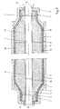
- FIG. 1 shows a torsion spring 1, which is used, for example, as a sectional door spring, d. H. for weight compensation on a sectional door can be used.
- the torsion spring 1 is made of spring steel wire 2 formed in a spiral around a spring axis 3 circumferential spring turns 4 is arranged.
- the torsion spring 1 has a smaller inner diameter at the spring ends 5 and 6 7 than in their central area 8.
- Connection elements matched while the inner diameter 7 of the Central area 8 on the specific stress of the torsion spring 1 is matched.
- the torsion spring 1 is here in one three-part die 9 to 11 arranged.
- the centerpiece 10 of the The die is cylindrical in shape and takes up the central area 8 with radial support of the spring turns 4 of the torsion spring 1 on.
- the head parts 9 and 11 of the die press the spring ends 5 and 6 of the torsion spring 1 together and seal the end faces 12 and 13 of the torsion spring 1 except for ice spray channels 14 in the Head part 9 and ventilation channels 15 in the head part 11.
- torsion spring arrangement For Production of a torsion spring arrangement is the first free Annulus 17 between the inner diameter 7 of the torsion spring 1 and an outer diameter 24 of the pipe section 16 through the Injection channels 14 sprayed with a substance 19, which in the annular space 17 forms an elastic foam.
- the foam puts on the spring turns 4. But it does not stick with the spring steel wire 2 because of this before ejecting the Torsion spring 1 on the inside of the torsion spring 1 with a Release agent and lubricant was treated.
- the annulus 17 is foamed, the air contained in it escapes the ventilation channels 15. Foaming is finished when the Foam emerges from the ventilation channels 15.
- the torsion spring assembly with the torsion spring 1 and that of the tube section 16 and the elastic jacket 18th formed carrier sleeve are removed from the die 9 to 11. Now there is no danger that the carrier sleeve both anchored positively and positively in the torsion spring 1 is, falls out of the torsion spring 1.
- the torsion spring 1 on torsion changes its inner diameter 7, and due to their torsion, the individual twist Spring turns 4 against each other.
- the change in diameter of the Inner diameter 7 is due to elastic deformation of the jacket 18 compensated, the jacket 18 with its surface 20th constantly rests on the spring turns 4 of the spring steel wire 2.
- the tubular sleeve 21 is made of elastic deformable material.
- the tubular Cover 21 via the injection channels 14 of the head piece 9, which here is shown as the only one from the die 9 to 11, where the tubular shell from the inside to the Torsion spring 1 creates.
- the spraying out of the casing 21 substance 22 used forms a hard foam. in the The result is the torsion spring arrangement 22 according to FIG. 3 receive.
- This consists of the torsion spring 1 and one Carrier sleeve viewed from the inside from the pipe section 16, then a hard jacket 23 around the pipe section 16 and ultimately from the elastic jacket 18 around the hard jacket 23 around, the hard shell 23 from the substance 24 and the elastic jacket 18 is formed by the sleeve 21.
- the surface 20 of the shell 21 or the elastic Jacket 18 in turn be designed so that the lowest possible Sliding friction forces between it and the spring steel wire 2 occur.
- FIG 4 Another embodiment of the torsion spring assembly 22 is shown in Figure 4. This differs from that according to Figure 3 in that a hard core of the carrier sleeve for the torsion spring only the hard shell 23 but not the Pipe section 16 includes. Rather, the pipe section 16 is here been pulled out. That means he only has part of the matrix served to eject the torsion spring 1.
- the Pipe section of course, no continuous central opening whether they have a recess in the center area at all. He can also be a solid rod.
- the new torsion spring arrangement and the process for its manufacture can also be applied to cylindrical torsion springs 1, the annulus in turn within the torsion spring what is cylindrical and thus geometrically simpler can translate into cost advantages.
- a substance to form an elastic Jacket 18 and a substance for foaming the annular space of can be introduced inside.
- it can be act only one substance.
- Substances can both substances in the annular space 17th be foamed. But it is also possible to use only one substance to foam, this corresponds to the embodiment according to Figure 2.
Landscapes
- Engineering & Computer Science (AREA)
- General Engineering & Computer Science (AREA)
- Mechanical Engineering (AREA)
- Springs (AREA)
Priority Applications (1)
| Application Number | Priority Date | Filing Date | Title |
|---|---|---|---|
| EP00101993A EP1122000A1 (fr) | 2000-02-02 | 2000-02-02 | Procédé de fabrication d'un arrangement de ressort à torsion et arrangement de ressort à torsion |
Applications Claiming Priority (1)
| Application Number | Priority Date | Filing Date | Title |
|---|---|---|---|
| EP00101993A EP1122000A1 (fr) | 2000-02-02 | 2000-02-02 | Procédé de fabrication d'un arrangement de ressort à torsion et arrangement de ressort à torsion |
Publications (1)
| Publication Number | Publication Date |
|---|---|
| EP1122000A1 true EP1122000A1 (fr) | 2001-08-08 |
Family
ID=8167746
Family Applications (1)
| Application Number | Title | Priority Date | Filing Date |
|---|---|---|---|
| EP00101993A Withdrawn EP1122000A1 (fr) | 2000-02-02 | 2000-02-02 | Procédé de fabrication d'un arrangement de ressort à torsion et arrangement de ressort à torsion |
Country Status (1)
| Country | Link |
|---|---|
| EP (1) | EP1122000A1 (fr) |
Citations (4)
| Publication number | Priority date | Publication date | Assignee | Title |
|---|---|---|---|---|
| DE1041816B (de) * | 1956-11-21 | 1958-10-23 | Mecano Bundy Ges Mit Beschraen | Federgehaenge fuer Blattfederungen, insbesondere fuer Kraftfahrzeuge |
| US3861661A (en) * | 1972-09-21 | 1975-01-21 | Nissan Motor | Compression spring assembly |
| JPS5794142A (en) * | 1980-12-01 | 1982-06-11 | Nhk Spring Co Ltd | Car suspension device |
| EP0965399A2 (fr) * | 1998-06-18 | 1999-12-22 | Société Alsacienne pour la Transformation de l'Acier S.a.r.l. | Procédé de fabrication d'un ressort en fil à partir d'un fil métallique dur ayant un section ronde |
-
2000
- 2000-02-02 EP EP00101993A patent/EP1122000A1/fr not_active Withdrawn
Patent Citations (4)
| Publication number | Priority date | Publication date | Assignee | Title |
|---|---|---|---|---|
| DE1041816B (de) * | 1956-11-21 | 1958-10-23 | Mecano Bundy Ges Mit Beschraen | Federgehaenge fuer Blattfederungen, insbesondere fuer Kraftfahrzeuge |
| US3861661A (en) * | 1972-09-21 | 1975-01-21 | Nissan Motor | Compression spring assembly |
| JPS5794142A (en) * | 1980-12-01 | 1982-06-11 | Nhk Spring Co Ltd | Car suspension device |
| EP0965399A2 (fr) * | 1998-06-18 | 1999-12-22 | Société Alsacienne pour la Transformation de l'Acier S.a.r.l. | Procédé de fabrication d'un ressort en fil à partir d'un fil métallique dur ayant un section ronde |
Non-Patent Citations (1)
| Title |
|---|
| PATENT ABSTRACTS OF JAPAN vol. 006, no. 187 (M - 158) 25 September 1982 (1982-09-25) * |
Similar Documents
| Publication | Publication Date | Title |
|---|---|---|
| DE69016707T2 (de) | Dynamischer Dämpfer. | |
| DE69300947T2 (de) | Gebaute Nockenwelle. | |
| WO2019115436A1 (fr) | Rail télescopique | |
| EP0324499A1 (fr) | Méthode de fabrication d'un arbre composite | |
| DE102008007153A1 (de) | Längenverstellbare Welle | |
| DE3701887A1 (de) | Zwischenlager fuer die antriebsgelenkwelle von kraftfahrzeugen | |
| DE69512608T2 (de) | Elastisches lager mit mindestens zwei zylindrischen buchsen, buchsen für ein solches lager und fabrikationsprozess des lagers mittels derartigen buchsen | |
| EP0137958A2 (fr) | Charge propulsive et son procédé de fabrication | |
| EP1122000A1 (fr) | Procédé de fabrication d'un arrangement de ressort à torsion et arrangement de ressort à torsion | |
| DE4233896C2 (de) | Kolben | |
| DE10337918A1 (de) | Twin-Ball-Gelenk mit verbessertem Kugelkäfig | |
| EP0472950B1 (fr) | Accouplement élastique | |
| DE3010690A1 (de) | Hydraulischer teleskopschwingungsdaempfer mit hydraulischem und elastischem zuganschlag, insbesondere fuer kraftfahrzeuge | |
| DE60021758T2 (de) | Anordnung mit einer hülse die auf einem metallischen zylinder installiert ist | |
| DE10206317B4 (de) | Schraubenfederanordnung | |
| DE60021764T2 (de) | Vorrichtung und methode, um den rotor eines hermetisch geschlossenen verdichters zu montieren | |
| DE60108632T2 (de) | Vorrichtung und verfahren zum einbringen von einsätzen in blasgeformte kunststoffelemente | |
| DE3700805C2 (fr) | ||
| DE2701295C2 (fr) | ||
| DE2731333C2 (fr) | ||
| DE102016214206A1 (de) | Vorrichtung zur Tilgung von Schwingungsresonanzen | |
| DE102019205667B4 (de) | Druckfeder zum Einsetzen in einen Spindelantrieb für ein Einstellelement einer Fahrzeugtür | |
| DE102021108998A1 (de) | Rillenkugellager sowie ein Verfahren zur Herstellung eines Rillenkugellagers | |
| EP0855233B1 (fr) | Procédé pour la fabrication de cylindres à amortissement de vibrations et jeu de cylindres | |
| DE3020497C2 (de) | Subzirkularer Rotor |
Legal Events
| Date | Code | Title | Description |
|---|---|---|---|
| PUAI | Public reference made under article 153(3) epc to a published international application that has entered the european phase |
Free format text: ORIGINAL CODE: 0009012 |
|
| AK | Designated contracting states |
Kind code of ref document: A1 Designated state(s): AT BE CH CY DE DK ES FI FR GB GR IE IT LI LU MC NL PT SE |
|
| AX | Request for extension of the european patent |
Free format text: AL;LT;LV;MK;RO;SI |
|
| AKX | Designation fees paid | ||
| REG | Reference to a national code |
Ref country code: DE Ref legal event code: 8566 |
|
| STAA | Information on the status of an ep patent application or granted ep patent |
Free format text: STATUS: THE APPLICATION IS DEEMED TO BE WITHDRAWN |
|
| 18D | Application deemed to be withdrawn |
Effective date: 20020209 |