EP1122030A2 - Outil abrasif - Google Patents
Outil abrasif Download PDFInfo
- Publication number
- EP1122030A2 EP1122030A2 EP01101689A EP01101689A EP1122030A2 EP 1122030 A2 EP1122030 A2 EP 1122030A2 EP 01101689 A EP01101689 A EP 01101689A EP 01101689 A EP01101689 A EP 01101689A EP 1122030 A2 EP1122030 A2 EP 1122030A2
- Authority
- EP
- European Patent Office
- Prior art keywords
- abrasive
- grain
- layer
- parts
- ultra
- Prior art date
- Legal status (The legal status is an assumption and is not a legal conclusion. Google has not performed a legal analysis and makes no representation as to the accuracy of the status listed.)
- Granted
Links
- 239000006061 abrasive grain Substances 0.000 claims abstract description 358
- 238000000227 grinding Methods 0.000 claims abstract description 281
- 239000010953 base metal Substances 0.000 claims abstract description 80
- 239000002184 metal Substances 0.000 claims abstract description 66
- 229910052751 metal Inorganic materials 0.000 claims abstract description 66
- 239000010410 layer Substances 0.000 claims description 479
- 239000007788 liquid Substances 0.000 claims description 41
- 239000011230 binding agent Substances 0.000 claims description 28
- 239000002245 particle Substances 0.000 claims description 25
- 230000002093 peripheral effect Effects 0.000 claims description 24
- 239000002356 single layer Substances 0.000 claims description 7
- 239000002699 waste material Substances 0.000 abstract description 64
- PXHVJJICTQNCMI-UHFFFAOYSA-N Nickel Chemical compound [Ni] PXHVJJICTQNCMI-UHFFFAOYSA-N 0.000 description 28
- 239000000203 mixture Substances 0.000 description 17
- 238000009713 electroplating Methods 0.000 description 16
- 238000005498 polishing Methods 0.000 description 16
- 239000002002 slurry Substances 0.000 description 15
- 238000004519 manufacturing process Methods 0.000 description 14
- XLYOFNOQVPJJNP-UHFFFAOYSA-N water Substances O XLYOFNOQVPJJNP-UHFFFAOYSA-N 0.000 description 14
- 230000000873 masking effect Effects 0.000 description 13
- 229910052759 nickel Inorganic materials 0.000 description 12
- 230000037452 priming Effects 0.000 description 12
- 238000005530 etching Methods 0.000 description 11
- 238000003754 machining Methods 0.000 description 9
- 230000003750 conditioning effect Effects 0.000 description 8
- 238000000151 deposition Methods 0.000 description 8
- 230000008021 deposition Effects 0.000 description 8
- 238000000034 method Methods 0.000 description 8
- 229910000990 Ni alloy Inorganic materials 0.000 description 7
- 230000000694 effects Effects 0.000 description 7
- 238000005520 cutting process Methods 0.000 description 6
- 229920001296 polysiloxane Polymers 0.000 description 6
- 230000001154 acute effect Effects 0.000 description 5
- 238000001816 cooling Methods 0.000 description 5
- 229910052802 copper Inorganic materials 0.000 description 5
- 230000007423 decrease Effects 0.000 description 5
- 230000001788 irregular Effects 0.000 description 5
- 238000007711 solidification Methods 0.000 description 5
- 230000008023 solidification Effects 0.000 description 5
- VYPSYNLAJGMNEJ-UHFFFAOYSA-N Silicium dioxide Chemical compound O=[Si]=O VYPSYNLAJGMNEJ-UHFFFAOYSA-N 0.000 description 4
- 229910003460 diamond Inorganic materials 0.000 description 4
- 239000010432 diamond Substances 0.000 description 4
- 239000002659 electrodeposit Substances 0.000 description 4
- 238000009825 accumulation Methods 0.000 description 3
- 230000035508 accumulation Effects 0.000 description 3
- 238000007599 discharging Methods 0.000 description 3
- 238000009760 electrical discharge machining Methods 0.000 description 3
- 230000002035 prolonged effect Effects 0.000 description 3
- 239000011347 resin Substances 0.000 description 3
- 229920005989 resin Polymers 0.000 description 3
- JOYRKODLDBILNP-UHFFFAOYSA-N Ethyl urethane Chemical compound CCOC(N)=O JOYRKODLDBILNP-UHFFFAOYSA-N 0.000 description 2
- QAOWNCQODCNURD-UHFFFAOYSA-N Sulfuric acid Chemical compound OS(O)(=O)=O QAOWNCQODCNURD-UHFFFAOYSA-N 0.000 description 2
- 239000003513 alkali Substances 0.000 description 2
- 239000002585 base Substances 0.000 description 2
- 230000015572 biosynthetic process Effects 0.000 description 2
- 238000004070 electrodeposition Methods 0.000 description 2
- 238000007747 plating Methods 0.000 description 2
- 239000004065 semiconductor Substances 0.000 description 2
- 239000000377 silicon dioxide Substances 0.000 description 2
- 238000009751 slip forming Methods 0.000 description 2
- 238000001238 wet grinding Methods 0.000 description 2
- QNRATNLHPGXHMA-XZHTYLCXSA-N (r)-(6-ethoxyquinolin-4-yl)-[(2s,4s,5r)-5-ethyl-1-azabicyclo[2.2.2]octan-2-yl]methanol;hydrochloride Chemical compound Cl.C([C@H]([C@H](C1)CC)C2)CN1[C@@H]2[C@H](O)C1=CC=NC2=CC=C(OCC)C=C21 QNRATNLHPGXHMA-XZHTYLCXSA-N 0.000 description 1
- GRYLNZFGIOXLOG-UHFFFAOYSA-N Nitric acid Chemical compound O[N+]([O-])=O GRYLNZFGIOXLOG-UHFFFAOYSA-N 0.000 description 1
- XUIMIQQOPSSXEZ-UHFFFAOYSA-N Silicon Chemical compound [Si] XUIMIQQOPSSXEZ-UHFFFAOYSA-N 0.000 description 1
- 238000005299 abrasion Methods 0.000 description 1
- 239000002253 acid Substances 0.000 description 1
- 230000009471 action Effects 0.000 description 1
- 230000000903 blocking effect Effects 0.000 description 1
- 229910052799 carbon Inorganic materials 0.000 description 1
- 239000003795 chemical substances by application Substances 0.000 description 1
- 239000013078 crystal Substances 0.000 description 1
- 230000007547 defect Effects 0.000 description 1
- 230000006735 deficit Effects 0.000 description 1
- 238000010586 diagram Methods 0.000 description 1
- 238000005868 electrolysis reaction Methods 0.000 description 1
- 238000005516 engineering process Methods 0.000 description 1
- 239000012634 fragment Substances 0.000 description 1
- 230000006872 improvement Effects 0.000 description 1
- 239000000463 material Substances 0.000 description 1
- 230000007246 mechanism Effects 0.000 description 1
- 230000004048 modification Effects 0.000 description 1
- 238000012986 modification Methods 0.000 description 1
- 229910017604 nitric acid Inorganic materials 0.000 description 1
- 230000008569 process Effects 0.000 description 1
- 230000001737 promoting effect Effects 0.000 description 1
- 230000005855 radiation Effects 0.000 description 1
- 230000000717 retained effect Effects 0.000 description 1
- 239000011435 rock Substances 0.000 description 1
- 229910052710 silicon Inorganic materials 0.000 description 1
- 239000010703 silicon Substances 0.000 description 1
- 238000005245 sintering Methods 0.000 description 1
- IFEJLMHZNQJGQU-KXXGZHCCSA-M sodium;(z)-7-[(1r,2r,3r,5s)-2-[(e,3r)-4-(3-chlorophenoxy)-3-hydroxybut-1-enyl]-3,5-dihydroxycyclopentyl]hept-5-enoate Chemical compound [Na+].C([C@H](O)\C=C\[C@@H]1[C@H]([C@@H](O)C[C@H]1O)C\C=C/CCCC([O-])=O)OC1=CC=CC(Cl)=C1 IFEJLMHZNQJGQU-KXXGZHCCSA-M 0.000 description 1
- 239000010935 stainless steel Substances 0.000 description 1
- 229910001220 stainless steel Inorganic materials 0.000 description 1
- 239000000126 substance Substances 0.000 description 1
Images


Classifications
-
- B—PERFORMING OPERATIONS; TRANSPORTING
- B24—GRINDING; POLISHING
- B24B—MACHINES, DEVICES, OR PROCESSES FOR GRINDING OR POLISHING; DRESSING OR CONDITIONING OF ABRADING SURFACES; FEEDING OF GRINDING, POLISHING, OR LAPPING AGENTS
- B24B53/00—Devices or means for dressing or conditioning abrasive surfaces
- B24B53/017—Devices or means for dressing, cleaning or otherwise conditioning lapping tools
-
- B—PERFORMING OPERATIONS; TRANSPORTING
- B24—GRINDING; POLISHING
- B24D—TOOLS FOR GRINDING, BUFFING OR SHARPENING
- B24D3/00—Physical features of abrasive bodies, or sheets, e.g. abrasive surfaces of special nature; Abrasive bodies or sheets characterised by their constituents
- B24D3/02—Physical features of abrasive bodies, or sheets, e.g. abrasive surfaces of special nature; Abrasive bodies or sheets characterised by their constituents the constituent being used as bonding agent
- B24D3/04—Physical features of abrasive bodies, or sheets, e.g. abrasive surfaces of special nature; Abrasive bodies or sheets characterised by their constituents the constituent being used as bonding agent and being essentially inorganic
- B24D3/06—Physical features of abrasive bodies, or sheets, e.g. abrasive surfaces of special nature; Abrasive bodies or sheets characterised by their constituents the constituent being used as bonding agent and being essentially inorganic metallic or mixture of metals with ceramic materials, e.g. hard metals, "cermets", cements
-
- B—PERFORMING OPERATIONS; TRANSPORTING
- B24—GRINDING; POLISHING
- B24B—MACHINES, DEVICES, OR PROCESSES FOR GRINDING OR POLISHING; DRESSING OR CONDITIONING OF ABRADING SURFACES; FEEDING OF GRINDING, POLISHING, OR LAPPING AGENTS
- B24B53/00—Devices or means for dressing or conditioning abrasive surfaces
- B24B53/12—Dressing tools; Holders therefor
-
- B—PERFORMING OPERATIONS; TRANSPORTING
- B24—GRINDING; POLISHING
- B24D—TOOLS FOR GRINDING, BUFFING OR SHARPENING
- B24D18/00—Manufacture of grinding tools or other grinding devices, e.g. wheels, not otherwise provided for
- B24D18/0018—Manufacture of grinding tools or other grinding devices, e.g. wheels, not otherwise provided for by electrolytic deposition
-
- B—PERFORMING OPERATIONS; TRANSPORTING
- B24—GRINDING; POLISHING
- B24D—TOOLS FOR GRINDING, BUFFING OR SHARPENING
- B24D7/00—Bonded abrasive wheels, or wheels with inserted abrasive blocks, designed for acting otherwise than only by their periphery, e.g. by the front face; Bushings or mountings therefor
- B24D7/06—Bonded abrasive wheels, or wheels with inserted abrasive blocks, designed for acting otherwise than only by their periphery, e.g. by the front face; Bushings or mountings therefor with inserted abrasive blocks, e.g. segmental
Definitions
- the present invention relates to an abrasive tool with metal binder phase, containing electrodeposited abrasive tool or metal bonded abrasive tool, used for the conditioner for carrying out conditioning of the polishing pad.
- an abrasive tool with metal binder phase containing electrodeposited abrasive tool or metal bonded abrasive tool, used for the conditioner for carrying out conditioning of the polishing pad.
- which is used for the polishing of the surface of workpiece, for example, a semiconductor wafer with CMP equipment etc.
- CMP equipment Chemical-Mechanical Polishing machine
- Fig. 32 As an example.
- a mirror polish is carried out so that a wafer may serve as high precision and the zero defect surface in connection with microfabrication of devices.
- the mechanism of polish by CMP is based on the mechano-chemical polishing method, compounded with the mechanical element by particle silica etc. (free abrasive grain) and the etching element by alkali liquid, acid liquid, etc.
- the polishing pad 4 which was attached in the main axis 2 as shown in Fig. 32, and consists, for example, of hard urethane is formed on the disk shaped rotation table 3 at this CMP equipment 1.
- wafer career 5, which can rotate on its axis, is laid out and attached, oppositely to this pad 4, and also in a position eccentric from the main axis 2 of a pad 4.
- This wafer career 5 is made into smaller disk form rather than the pad 4, and holds a wafer 6. And this wafer 6 is arranged between the wafer career 5 and the pad 4, and a mirror polish is offered and carried out to polishing the surface by the side of a pad 4.
- the free abrasive grain which consists of the particle silica mentioned above, is used as a polish agent.
- mixtures such as alkali liquid for etching, are supplied on the pad 4 as liquefied slurry s.
- this slurry s flows between the wafer 6 held at the wafer career 5, and the pad 4.
- the wafer 6 rotates on the wafer career 5, and the pad 4 rotates simultaneously around the main axis 2 as a center.
- polish of the wafer 6 is performed by slurry s held in these foamed layers. Then, the problem arises that the polish accuracy and polish efficiency of wafer 6 falls, because the flatness of the polishing surface of the pad 4 falls or clogging occurs by repeating polish of wafer 6.
- the pad conditioner 8 is formed in the CMP equipment 1 and used for re-polish or re-grinding (conditioning) of the surface of a pad 4.
- An electrodeposited abrasive wheel 11 is attached to this pad conditioner 8,attached through an arm 10 to the rotation axis 9, which is formed in the exterior of the rotation table 3.
- both-way rocking of the electrodeposited abrasive wheel 11 is carried out on the rotating pad 4.
- the surface of pad 4 is ground, the flatness of the surface of pad 4 is recovered or maintained, and clogging is canceled.
- a plane and ring-like abrasive grain layer 13 is formed by fixed width on the disk-formed base metal 12.
- this abrasive grain layer 13 is constituted of ultra abrasive grains 14 on the base metal 12, such as a diamond and cBN, distributed and fixed by the electrodeposited metal phase 15 by electroplating etc.
- This electrodeposited metal phase 15 consists of nickel etc.
- the concave groove 17 is formed in the surface of the abrasive grain layer 13 in the direction of diameter at intervals of predetermined, such as 45 degrees, then slurry s and ground wastes will be discharged outside through this concave groove 17.
- the electrodeposited abrasive wheel 11 should be carried out both-way rocking on pad 4, covering the distance equivalent to the radius of pad 4 at least.
- Nap raising of pad 4 is beaten and cut, while the ultra abrasive grains 14, distributed on the abrasive grain layer 13, carries out grinding.
- the ultra abrasive grains 14 are protruded from the surface of the abrasive grain layer 13, which performs as grinding surface, only about 1/3 of the mean particle diameter of the ultra abrasive grains 14 in this case.
- This electrodeposited abrasive wheel gathers 2-10 ultra abrasive grains, and laid out these grains in the shape of islands.
- These islands-like ultra abrasive grains are distributed on the surface of the abrasive grain layer, which corresponds to a grinding surface, in order to prevent clogging at the time of grinding, and also to continue grinding for a long period of time.
- ultra abrasive grains are electrodeposited and fixed on a flat base-metal surface.
- the difference of the height between the electrodeposited-metal-phase surface of the abrasive grain layer, and the ultra abrasive grains protruded from this surface is only less than about 1/2 of the mean particle diameter of ultra abrasive grains substantially.
- this electrodeposited abrasive wheel is used as a pad conditioner.
- grinding work piece has a composition with much elasticity or flexibility as like the pad 4 of CMP equipment 1,which consists of elastic nap raising 1.7 mm in thickness with foamed layer and an under laid cushion layer with a thickness of about 3.5mm.
- the whole abrasive-grain-layer surface will make direct contact with grinding workpiece in this case, since the height difference is less than about 1/2 of the mean particle diameter of ultra abrasive grains.
- the abutment pressure disperses from ultra abrasive grains and becomes slippery, and nap raising could not be cut and fallen down.
- the grinding liquid (for example, pure water) of pad 4 is flipped out.
- pad 4 becomes easy to dry and appears a fault that wet grinding becomes spoiled.
- the object of the present invention is to provide an abrasive tool with metal binder phase, such as an electrodeposited abrasive tool, having sufficient sharpness and good discharge performance to ground wastes.
- the other object of the present invention is to provide an abrasive tool, above-mentioned, which provides clean cut end of the opening of the foamed layer of polishing pad, does not occur clogging, and enables to hold slurry in foamed layer.
- the other additional object of the present invention is to suppress vibration at the time of grinding.
- the other additional object of the present invention is to suppress the solidification of various grinding wastes and slurry s, retained and staid between ultra abrasive grains, and to enable effective discharge.
- the other additional object of the present invention is to improve stability at the time of grinding, and to suppress the fall of the sharpness by clogging etc.
- the other additional object of the present invention is to suppress the generation of the deficit or crush, etc. at the sharp portion of ultra abrasive grains.
- one aspect of the abrasive tool with metal binder phase is characterized by several protruded parts formed in a base metal, and several small abrasive-grain-layer parts, laid out at intervals, to which ultra abrasive grains are adhered with metal binder phase on these protruded parts.
- the small abrasive-grain-layer part may be equipped with plural ultra abrasive grains, respectively.
- the height difference between the ultra abrasive grains in small abrasive-grain-layer parts and bottom part of the abrasive-grain-layer among small abrasive-grain-layer parts is large, because the ultra abrasive grains are formed in small abrasive-grain-layer parts.
- ultra abrasive grains at small abrasive-grain-layer parts contact and carry out grinding against grinding work piece. Then high grinding pressure can be maintained at ultra abrasive grains, and sharpness is improved.
- grinding liquid can be held at the bottom of abrasive-grain-layer among the small abrasive-grain-layer parts. Then the discharge of ground wastes is improved and ground wastes do not bring out clogging at the portion of ultra abrasive grains.
- the gap between small abrasive-grain-layer parts at an abrasive grain layer and the bottom of an abrasive-grain-layer can make larger than the mean particle diameter of ultra abrasive grains, and can be obtained at large value. Then, without occurring whole surface contact, high abutment pressure can be maintained at the ultra abrasive grains of small abrasive-grain-layer parts, sharpness is also improved. And grinding liquid etc. can be held at the bottom part of abrasive-grain-layer, the discharge performance of a ground wastes is improved, then ground wastes do not bring out clogging at the portion of ultra abrasive grains.
- the protruded parts mostly in the columnar shape with a comer R part and the top part, and ultra abrasive grains can be attached at these comers R part and the top part.
- the ultra abrasive grains at comer R part perform rough grinding, and subsequently, ultra abrasive grains at the top can perform finish grinding.
- ultra abrasive grains may drop out, at the time of grinding. Then, tool life may be shortened, and ultra abrasive grains may stick to grinding work piece, such as polishing pad, and causes damaging of the pad.
- the area of ultra abrasive grains exceeds 80%, there is a possibility that an electrodeposited abrasive tool may cause clogging.
- the small abrasive-grain-layer parts at the periphery domain except for the central domain of the surface of an abrasive grain layer.
- the abrasive grain layer is equipped with a central domain and a peripheral domain, and at the central domain, plural above-mentioned small abrasive-grain-layer parts are formed and set at intervals mutually.
- ultra abrasive grains are attached to these small abrasive-grain-layer parts by the metal binder phase, respectively.
- ultra abrasive grains are attached to peripheral domain by the metal binder phase.
- the concentration of the ultra abrasive grains at peripheral domain is higher than the central domain.
- the grinding surface of the electrodeposited abrasive tool has a peripheral domain with higher concentration of ultra abrasive grains than a central domain.
- the grinding surface contacts to grinding work piece stably by the abrasive grain layer at peripheral domain.
- high abutment pressure can be obtained at the ultra abrasive grain of the small abrasive-grain-layer parts within central domain. Then, while grind machining, cut can be performed cleanly.
- the height difference between the bottom of abrasive-grain-layer among the neighboring small abrasive-grain-layer parts and small abrasive-grain-layer parts can be made large.
- the ultra abrasive grains at small abrasive-grain-layer parts contact to a polishing work piece and carry out grinding, then high abutment pressure can be maintained and sharpness is maintained.
- the ultra abrasive grains at peripheral domain may be individually distributed in the metal binder phase.
- plural small abrasive-grain-layer parts may be constituted like a central domain, and the small abrasive-grain-layer parts may be laid out at smaller mutual intervals than central domain.
- the interval may be made the same as that of a central domain, and make the numbers of ultra abrasive grains attached to each small abrasive-grain-layer part more than that of central domain.
- the other aspect of the abrasive tool concerning to the present invention is characterized by arranging several small abrasive-grain-layer parts, which have the opening for discharging grinding liquid, and forming them approximately in the center.
- the openings are prepared approximately in the center of a small abrasive-grain-layer part, and supplies grinding liquid to the ultra abrasive grain of the circumference, it can be able to supply grinding liquid directly to the grinding point at the ultra abrasive grain.
- the discharge way may be formed at other domain different from small abrasive-grain-layer parts (protruded part).
- grinding liquid spreads around at grinding point sufficiently, and prevents to accumulate grinding wastes on ultra abrasive grains, and wash away them smoothly.
- the diameter of the opening at small abrasive-grain-layer parts may be in the range ⁇ 0.5-3.0mm.
- the diameter (D) of protruded parts may be 2 to 10 times larger than the diameter (d) of an opening.
- the range of the height of the protruded parts to base metal may be within 0.1-5.0mm.
- the range of the distance between adjacent protruded parts (L) may be 1/3 ⁇ 2 time of the mean outer diameter (D) of protruded parts.
- the interval of small abrasive-grain-layer parts can be set up pertinently, the abutment pressure of ultra abrasive grains can be maintained at high value, and moreover various grinding wastes can be smoothly discharged with grinding liquid through this gap.
- the abrasive grain layer may be formed in the shape of a ring with two or more layers, or in the shape of spiral.
- the sum of the grinding length of each abrasive grain layer, in the direction almost parallel to the relative movement direction of a grinding work piece, can be made almost uniform at arbitrary position of the direction which intersects almost perpendicularly in the movement direction of grinding work piece.
- an abrasive grain layer is constituted from three or more layers, the sum of the area of the abrasive-grain-layer domain in the arbitrary position, which intersects perpendicularly in the direction almost parallel to the relative movement direction of a grinding work piece, can be easily made into uniform.
- the discharge path may be formed among the abrasive grain layers of two or more layers in the direction of a diameter at intervals.
- the discharge path may consist of the sub-discharge path formed among the small abrasive-grain-layer parts adjoined each other, and also of main discharge path formed among the plural abrasive grain layers, which are in the shape of a ring or spiral, adjoined each other in the direction of diameter.
- a single layer of ultra abrasive grains may be adhered to the metal binder phase of the small abrasive-grain-layer part toward the thickness direction, and called as a single layer abrasive tool.
- the abrasive tool with metal binder phase may possess the first small abrasive-grain-layer parts and the second small abrasive-grain-layer parts.
- the first small abrasive-grain-layer parts inclines one directionally against the central line toward the direction of a diameter, and the second small abrasive-grain-layer parts inclines to the opposite direction against the first small abrasive-grain-layer parts mentioned above.
- the stability of the grinding tool is improved at the time of grinding.
- the contact surface and contact pressure to the grinding work piece are also stabilized, then minute vibration etc. is suppressed, and grinding work piece is not damaged even at partial area.
- first and second small abrasive-grain-layer parts are inclined toward the central line in right and opposite direction respectively, clogging are canceled and fall of sharpness can be prevented in such way.
- the second abrasive-grain-layer parts have short grinding length.
- first and second small abrasive-grain-layer parts may be different in aspect ratio respectively.
- Stability is improved, and if an aspect ratio is small, the capability of clogging cancellation will be improved.
- small abrasive-grain-layer parts may be dissociated mutually, and mostly in rhombic shape, and may be arranged in radiation pattern.
- first and second small abrasive-grain-layer parts are arranged in the direction of a circumference of base metal in turn, and the abrasive grain layer may be making the shape of a ring.
- one of the first and second small abrasive-grain-layer parts may cause clogging because of long grinding length, another can cancel clogging since grinding length is short, then the fall of sharpness can be prevented.
- Small abrasive-grain-layer parts have the portion with one-directionally inclined toward the central line of the direction of diameter passing through the center of a base metal, and the portion which inclines to an opposite direction.
- the small abrasive-grain-layer parts may contain the third small abrasive-grain-layer parts and the fourth smallness abrasive-grain-layer parts, that are formed in the shape of curve and countered on both sides of a central line, faced both sides, or slipped each other along with central line.
- the small abrasive-grain-layer parts may be arranged all over the base metal, and can promote increase the amount of grinding much more and also cancellation of clogging.
- small abrasive-grain-layer parts are characterized by a single ultra abrasive grain adhered at the metal binder phase.
- ultra abrasive grain may be adhered at the small abrasive-grain-layer parts formed at the concave parts at the upper surface of the protruded parts of a base metal.
- ultra abrasive grains are laid and adhered by electroplate etc. at the concave part of protruded parts on manufacturing of an abrasive tool, then positioning of ultra abrasive grains are easy, and it can be projected and laid so that the comer part of the crystal object of an ultra abrasive grain may turn toward upper part tip.
- the outer diameter (D) of protruded parts may be 1.3 to 3 times as much range as the mean particle diameter of an ultra abrasive grain.
- the range of the height (H) of the protruded parts to a base metal may be within 0.05-3.0mm.
- grinding liquid and grinding wastes are poured easily and can be discharged between grinding point and the discharge path on a base metal,.
- An electrodeposited abrasive tool concerning the present invention characterized by blocky ultra abrasive grains.
- the blocky ultra abrasive grains have the shape of regular polygons, such as a right hexagon, which the corner part has seldom jutted out, or the shape near form sphere, comer part or ridgeline part, etc. are seldom crushed or drop out, and seldom produces the fragment by crush etc.
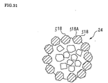
- ultra abrasive grains are singly and was mutually distributed, and the small abrasive-grain-layer parts, where plural blocky ultra abrasive grains are gathered and adhered by the metal binder phase, are laid out and distributed mutually.
- cutting in and cutting performance are rather good and grinding performance is kept in good condition, because grinding is performed at the ridgeline of the array of ultra abrasive grains around perimeter area, if the ultra abrasive grains are gathered.
- ultra abrasive grains adhere to the small abrasive-grain-layer part, and blocky ultra abrasive grains may be laid out at the perimeter.
- the ultra abrasive grain prepared at each small abrasive-grain-layer parts may be made into 1-500 pieces, and the ratio of the ultra abrasive grains to the whole surface product of the above-mentioned abrasive grain layer accounted by plane projection may be set as 2% - 80% of the range.
- an electrodeposited abrasive tool concerning to this invention may be CMP conditioner.
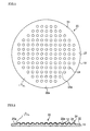
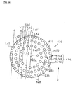
- Fig. 1 is a plane view of the polishing surface of the electrodeposited abrasive wheel of the first example of the present invention.
- Fig. 2 is a longitudinal section at the center part of the electrodeposited abrasive wheel shown in Fig. 1.
- Fig. 3 is a expanded sectional view of the principal part of the small abrasive-grain-layer part of the electrodeposited abrasive wheel shown in Fig. 2.
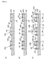
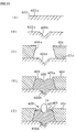
- Fig. 4 The manufacturing process of the electrodeposited abrasive wheel according to an example of this invention is shown in Fig. 4 as (A), (B), (C), and (D).
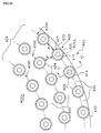
- Fig. 5 is a photograph 500 times enlarged showing a part of pad, which carried out grinding by the electrodeposited abrasive wheel of an example of this invention.
- Fig. 6 is a photograph 500 times enlarged showing a part of pad, which carried out grinding by the electrodeposited abrasive wheel which has the composition of the conventional example.
- Fig. 7 is a plane view of the polishing surface of the electrodeposited abrasive wheel according to the second example of the present invention.
- Fig. 8 is a longitudinal section at the central part of the electrodeposited abrasive wheel shown in Fig. 7.
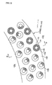
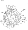
- Fig. 9 is a plane view of the polishing surface of the electrodeposited abrasive wheel according to the third example of the present invention.
- Fig. 10 is a partial expanded sectional view of the central domain and the peripheral domain of the electrodeposited abrasive wheel shown in Fig. 9,.
- Fig. 11 is a plane view of the surface equipped with the abrasive grain layer of the wheel according to the fourth example of the present invention.
- Fig. 12 is a partial enlargement of the second abrasive grain layer of the wheel shown in Fig. 11.
- Fig. 13 is a sectional view at B-B line of the wheel shown in Fig. 12.
- Fig. 14 shows the manufacturing process of the wheel according to the fourth example, as (A) of, (B), and (C).
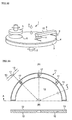
- Fig. 15 is a figure showing the relation of the abrasive-grain-layer position and work load in the rotation direction of a pad, about the half-circled portion of the wheel shown in Fig. 11 indicated by dashed line.
- Fig. 16 is a plane view of the wheel according to the fifth example of the present invention.
- Fig. 17 is a plane view of the wheel according to the sixth example.
- Fig. 18 is a partial enlargement of the abrasive grain layer of the wheel shown in Fig. 17.
- Fig. 19 is a sectional view at C-C line showing other form of the small abrasive-grain-layer parts.
- Fig. 20 is a partial enlargement of the abrasive grain layer of the wheel according to the seventh example of this invention.
- Fig. 21 is a partial enlargement of the abrasive grain layer of the wheel according to the eighth example.
- Fig. 22 is a partial enlargement of the abrasive grain layer of the wheel according to the ninth example.
- Fig. 23 is a partial enlargement of the abrasive grain layer of the wheel according to the tenth example.
- Fig. 24 is a plane view of the surface equipped with the abrasive grain layer of the wheel according to the eleventh example.
- Fig. 25 is a partial enlargement of the abrasive grain layer of the wheel shown in Fig. 24.
- Fig. 26 is a sectional view at D-D line of the small abrasive-grain-layer parts of the wheel shown in Fig. 25.
- Fig. 27 (A), (B), (C), (D), and (E) are the figures showing the manufacturing process of the wheel according to the eleventh example of the present invention.
- Fig. 28 is a plane view of the wheel according to the twelfth example.
- Fig. 29 shows the examples of modification of the protruded part of the small abrasive-grain-layer parts, (A) shows a plane view and a central longitudinal section view of the other protruded parts, and (B) shows the plane view and side view of another protruded parts.
- Fig. 30 shows the ratio of the diameter of the longest two symmetry axes on the image of ultra abrasive grains, which are projected two-dimensionally, (A), (B), and (C) show a blocky ultra abrasive grain, and (D) shows an irregular ultra abrasive grain.
- Fig. 31 is a plane view of the small abrasive-grain-layer parts shown in Fig. 30.
- Fig. 32 is a perspective diagram of the principal parts of the conventional CMP equipment.
- FIG. 33 (A) shows a partial plane view of the electrodeposited abrasive wheel in Fig. 32, and (B) shows the longitudinal section at A-A line of (A).
- Fig. 34 is a partial longitudinal section of the abrasive grain layer shown in Fig. 33.
- An abrasive grain layer 22 is formed at the surface of one-side 19a, and the grinding surface 20a is formed at the surface.
- the mound part 21 is arranged to the central domain in the shape of an almost lattice or meshes, and except for the ring shaped periphery domain 23 at the perimeter of one-side 19a.
- the ultra abrasive grains 14, such as a diamond and cBN, are arranged in the electrodeposited metal phase 25 which consists of nickel, for example, and manufactured by electroplating for example.
- the ultra abrasive grain 14 are adhered only on each mound part 21, and is not prepared at the bottom of abrasive-grain-layer 22a among the mound part 21 and the mound part 21.
- the small abrasive-grain-layer part 24 is prepared at the domain of an abrasive grain layer 22, and consists of the ultra abrasive grain 14, which were prepared along the surface almost columnar shaped, and the electrodeposited metal phase 25.
- each mound part 21 of a base metal 19 is formed by side wall 21c, comer R part 21a, and top 21b, and constituted, for example, with the ultra abrasive grains 14 within the ranges of 11-500 pieces adhered by the electrodeposited metal phase 25, on its whole surface.
- each small abrasive-grain-layer part 24 is taken within the range of ⁇ 1-10mm.
- Height H from the bottom of abrasive-grain-layer 22a is taken more than the mean particle diameter of an ultra abrasive grain 14, and taken more than twice of mean particle diameter in desirable case.
- the mean particle diameter of an ultra abrasive grain 14 is set less than 1 mm, for example, from 0.1mm - to about 0.7mm.
- Height H was set more than the mean particle diameter of ultra abrasive grain 14, because only the ultra abrasive grains 14 contact to pad 4, at the time of the grinding of a pad 4, and make the bottom of abrasive-grain-layer 22a not to contact to pad 4.
- each small abrasive-grain-layer part 24 shall be in the same height.
- the area of the ultra abrasive grains 14 is set within the range of 20% - 80% to the whole surface of polishing-surface 20a of an electrodeposited abrasive wheel 20 by plane projection.
- an ultra abrasive grain 14 If the area of an ultra abrasive grain 14 is less than 20%, there will be a possibility that an ultra abrasive grain 14 may drop out, at the time of grinding, and tool life will become short.
- the electrodeposited abrasive wheel 20 according to the present embodiment is constituted as mentioned above.
- Fig.4 explains the manufacture method of an electrodeposited abrasive wheel 20.
- Fig. 4 (A) one-side of the disk formed base metal 19, which is consist of SUS304 etc., 19a, is removed by etching etc., and plural mound parts 21A with almost columnar shape are left in the lattice pattern.
- bottom part 22A The portion removed by etching makes bottom part 22A.
- Sulfuric acid or nitric acid may be sprayed on one-side 19a with a high-pressure jet, or by electrolysis etching or electrical discharge machining, then it leaves mound part 21A-- specifically and other portions may be carved.
- mound parts 21A-- shown in Fig. 4 (B) are formed at one-side 19a with concave convex surface remained in the shape of a lattice.
- Each mound part 21A becomes into almost columnar shape with predetermined outer diameter D and height H'.
- the mound parts 21 are chamfered and formed into almost columnar shape shown in Fig. 4 (C) by polishing the edge of each mound parts 21A with the shot blast, barrel polish, etc. on this one-side 19a.
- the base metal 19 shown in Fig. 4 (C) may be formed by model fabrication.
- a priming electroplated thin layer is prepared on all over surface of each mound parts 21 as priming electroplated layer 25, consists of nickel (Cu, Cr, etc. are sufficient).
- the second electrodeposited-metal-phase 25c which consists of nickel (Cu, Cr, etc. are sufficient), for example, is formed on the whole surface with electroplating again.
- the bottom part 22A of base metal 19 is constituted as the abrasive-grain-layer bottom 22a.
- the ultra abrasive grains 14 are adhered by electrodeposited metal phase 25, which consists of priming electroplate layer 25a and the first and second electrodeposited metal phase 25b and 25c.
- abrasive grain layer 22 is prepared as shown in Fig. 3 and 4 (D) and electrodeposited abrasive wheel 20 is formed.
- Arrangement of the small abrasive-grain-layer parts 24 may be carried out at all over grinding-surface 20a, without being limited to above example.
- the electrodeposited abrasive wheel 20 according to the embodiment is prepared with above-mentioned composition.
- the arm 10 of the CMP equipment 1 shown in Fig. 32 is equipped with an electrodeposited abrasive wheel 20, the arm 10 is rocked, for example, toward the pad 4 on the rotating table 3, when the conditioning of a pad 4 are performed.
- both-way rocking of the electrodeposited abrasive wheel 20 is carried out, and the grinding of the pad 4 is carried out, then the flatness is recovered or maintained.
- the ultra abrasive grains 14 at the comer R part 21a perform rough grinding of a pad 4 first.
- the ultra abrasive grains 14 at the top part 21b, which follows corner R part 21 a, can perform finish grinding.
- the ultra abrasive grains 14 are adhered along with comer R part 21a to top part 21b on the mound parts 21.
- the abutment pressure can be highly maintained at the ultra abrasive grains 14, and sharpness is maintained.
- the opening of the foamed layer on pad 4 is cut cleanly and an opening is not crushed, then the holding capability of slurry s can be highly maintained.
- abrasive-grain-layer 22a does not contact with pad 4 and pad 4 contact only with the ultra abrasive grain 14 of the small abrasive-grain-layer part 24 at the time of grinding.
- grinding liquid can held at the bottom of abrasive-grain-layer 22a among the small abrasive-grain-layer parts 24, and moreover, ground wastes etc. can be discharged through the bottom of abrasive-grain-layer 22a.
- Fig. 5 is a 500 times enlarged photograph of the surface of pad 4.
- the openings k of the foamed layer does not suffer crush, and the grinding of the surface of a pad 4 is carried out cleanly, and the flatness has been recovered.
- Fig. 6 is a 500 times enlarged photograph of the surface of pad 4.
- the grinding is carried without contacting the bottom of abrasive-grain-layer 22a, but the ultra abrasive grains 14 of the small abrasive-grain-layer part 24 contacts pad 4.
- ground wastes does not remain at ultra abrasive grains 14, clogging does not occur and the discharge performance of ground wastes is good.
- grinding liquid are held among the small abrasive-grain-layer part 24 and bottom of abrasive-grain-layer 22a, which is among 24, and wipe out of the grinding liquid at the foamed layer of a pad 4 is suppressed.
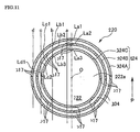
- an abrasive grain layer 22 is formed on one-side 19a of base metal 19, and the small abrasive-grain-layer parts 24 are not formed in the central domain 31 of abrasive grain layer 22, but two or more layers of small abrasive-grain-layer parts 24 - are arranged at the periphery domain 32 in the shape of concentric circle up to the perimeter edge.
- the bottom of abrasive-grain-layer 22a is arranged among the adjoining small abrasive-grain-layer parts 24.
- the electrodeposited abrasive wheel 30 according to the embodiment may be used equipped to the wafer career 5, in stead of conditioner 8,and rotated at eccentric position to pad 4 and carrying out grinding of pad 4.
- small abrasive-grain-layer part 24 - may be laid out spirally at the periphery domain 32, in stead of electrodeposited abrasive wheel 30 according to the embodiment equipped with small abrasive-grain-layer part 24 - in the shape of a concentric circle.
- the small abrasive-grain-layer parts 24 may be arranged in the shape of lattice or meshes of a net etc. at the arbitrary intervals.
- these small abrasive-grain-layer parts 24 may be prepared on all over polishing-surface 20a.
- the small abrasive-grain-layer parts 24 and the mound part 21 were formed in the almost columnar shape according to the embodiment mentioned-above, the form of the small abrasive-grain-layer parts 24 or the mound parts 21 are not limited to this example.
- They may be in the shape of a convex curved surface, such as the shape of a hemisphere or triangular pyramid form, if the height H from the bottom of abrasive-grain-layer 22a is more than the mean particle diameter of an ultra abrasive grain 14.
- the electrodeposited abrasive wheel 120 (electrodeposit abrasive tool) according to the embodiment is the same basic composition with the electrodeposited abrasive wheel 20 according to the first embodiment.
- the surface of the abrasive grain layer 122 corresponds to grinding-surface 20a, and its almost circular central domain is124, and the ring-like shaped outer domain is the periphery domain 126.
- plural mound parts 21 - with almost columnar shape are arranged at the central domain 124 in the shape of lattice, or meshes with predetermined intervals.
- the height of the convex plane part 127 is set as the same with mound part 21 --.
- plural ultra abrasive grains 14 are adhered by the electrodeposited metal phase 25 only on each mound part 21.
- the bottom of abrasive-grain-layer 22a among the mound part 21 is prepared as electrodeposited metal phase 25, and the ultra abrasive grains 14 are not formed.
- the electrodeposited metal phase 25 does not need to be formed at the bottom of abrasive-grain-layer 22a, and in this case, the bottom of abrasive-grain-layer 22a is composed with the exposed surface of base metal 19.
- an abrasive grain layer 22 is the small abrasive-grain-layer parts 24 in which the ultra abrasive grains 14 and the electrodeposited metal phase 25 were formed along the surface of the almost columnar shape.
- the manufacture method of the electrodeposited abrasive wheel 120 according to the embodiment is almost the same as that of the first embodiment.
- each of the mound parts 21 on base metal 19 will be formed by side wall 21c, which was formed at all circumferences, and comer R part 21a, and top part21b.
- the ultra abrasive grains 14 with the range of 11-500 pieces are adhered on whole surface by the electrodeposited metal phase 25.
- ultra abrasive grains 14 are distributed and fixed separately on the ring-like convex plane part 127 with the electrodeposited metal phase 25.
- ultra abrasive grains 14 are in same height H as the small abrasive-grain-layer part 24.
- degree of concentration of ultra abrasive grains 14 at the periphery domain 126 is set higher than the degree of concentration of ultra abrasive grains 14 at the central domain 124.
- priming electroplate of thin layer which consists of nickel (Cu, Cr, etc. are sufficient) all over the convex plane part 127 and each mound parts 21 is performed as priming electroplate layers 25a and 25b.
- a masking sheet is stripped from one-side 21a, electroplated again on the whole surface, and the second electrodeposited metal phase 25e and 25f are formed, for example from nickel (Cu, Cr, etc. are sufficient).
- the second electrodeposited metal phase 25e and 25f may be formed only at the convex plane part 127 and the mound part 21.
- electrodeposited metal phase 25 is not formed at the bottom of abrasive-grain-layer 22a which makes a concave part.
- the abrasive grain layer 122 to which the ultra abrasive grain 14 adhered at the mound parts 21 and the convex plane part 127 respectively, is formed by the electrodeposited metal phase 25 and shown in Fig. 10.
- the electrodeposited metal phase 25 consist of priming electroplate layers 25a and 25b, and the first and second electrodeposited metal phases 25c, 25d, 25e, and 25f. Then the electrodeposited abrasive wheel 120 is formed.
- the degree of concentration of the ultra abrasive grains 14 at periphery domain 126 can be set higher than that of the central domain 124 by arranging the interval of the small abrasive-grain-layer parts 24 suitably.
- electroplating may be carried out separately by masking one side of the convex plane part 127 in turns with mound part 21 -.
- the degree of concentration at the periphery domain 127 and the central domain 124 may be controlled as different value.
- abrasive grain layer 24 may be formed directly by electroplating, without preparing priming electroplate layer to the mound parts 21 and the convex plane part 127 on a base metal 19.
- the diameter of the electrodeposited abrasive wheel 120 is set, for example as 101mm, and the width of the peripheral domain 126 is set, for example as about 3mm or less.
- the area of the ultra abrasive grains 14 to the whole surface area of grinding-surface 20a is set within the range of 20% - 80%, accounted by plane-projection of the electrodeposited abrasive wheel 120.
- the electrodeposited abrasive wheel 120 according to the embodiment is equipped with the composition mentioned-above, and conditioning is performed like the form of the first embodiment.
- the degree of concentration of ultra abrasive grains 14 is higher at peripheral domain 126 on polishing-surface 20a than the central domain 124.
- ground wastes etc. can be discharged outside from the concave groove 17 suitably prepared in the peripheral domain 126.
- the influence on sharpness is small and hardly make bad influence on the grinding performance at the central domain 124, because the width of the periphery domain 126 is set as about 3mm or less.
- the vibration at the time of grinding can be suppressed, because plane balance can be kept in good condition by the contact of peripheral domain 126 of electrodeposited abrasive wheel 120 to pad 4.
- the abutment pressure at ultra abrasive grains 14 is high, and rough grinding and finish grinding can be performed continuously, and sharpness is good.
- many small abrasive-grain-layer parts 24 may be formed at predetermined intervals like the central domain 124, and ultra abrasive grains 14 on the mound parts 21 may be adhered by the electrodeposited metal phase 25.
- the number of the ultra abrasive grains 14, which adhered to the small abrasive-grain-layer parts 24 at the peripheral domain 126, may be more than the small abrasive-grain-layer part 24 at the central domain 24.
- the arrangement of the small abrasive-grain-layer parts 24 at the central domain 124 may be properly adopted into the shape of concentric circle, and spiral etc., in stead of the shape of lattice or meshes.
- abrasive tool with metal binder phase should be preferable, which may be made to hold ultra-abrasive grains by sintering without using electroplating as electrodeposited metal phase 25 etc.
- the wheel 220 (single layer abrasive tool) according to the fourth embodiment is shown in Fig. 11.
- the wheel is prepared and constituted of plural layers (three layers in figure) of abrasive grain layer 224,which is formed in the shape of ring with concentric circle (or may not be concentric circle), prepared at the perimeter side of one-side 222a, which is mostly round shaped on the disk shaped base metal 222.
- the first abrasive-grain-layer 224A is formed at outermost part with maximum diameter (for example, the same diameter as a base metal 222) on abrasive grain layer 224.
- the second abrasive-grain-layer 224B is formed at an interval
- the third abrasive-grain-layer 224C which have minimum diameter at the innermost part, is formed at an interval.
- the abrasive grain layer is not formed inside of the third abrasive-grain-layer 224C.
- the ring shaped domain from the first to the third abrasive-grain-layer 224A, and B and C, at one-side 222a on base metal 222, is set higher than other domains in thickness. (for example, the difference of height H shown in Fig. 13)
- first base metal part 222A second base metal part 222B, and third base metal part 222C.
- second base-metal part 222B shown in Fig. 12 and 13 plural cylindrical mound parts 225 (protruded parts) are formed at intervals of predetermined, and the opening 226 of a cross-sectional round shape is formed at the center.
- the ultra abrasive grains 214 such as diamond and CBN, are distributed and adhered on this small abrasive-grain-layer parts 228 by the metal binder phase (electrodeposited metal phase) 215 of nickel or nickel alloy.
- An ultra abrasive grains 214 constitute the single layer abrasive tool, which arranges only one layer in the thickness direction, and for example, this small abrasive-grain-layer part 228 is manufactured by electroplating.
- a water path 230 is formed covering the domains from the first to the third abrasive-grain-layer parts 224A, 224B, and 224C.
- This water path 230 pass through the openings 226 formed in the center of each small abrasive-grain-layer parts 228 prepared from the first to the third abrasive grain layer 224A, 224B, and 224C.
- Pure water is supplied as grinding liquid from the supply source, which is not illustrated, and circulated through the inside of the water path 230, then discharged outside from each opening 226.
- the inner diameter d of opening 226 is set as the range of 0.5-3mm, and the diameter D of the mound part 225 (protruded part) is set within the range of 2d-10d.
- the height h of the mound part 225 from each base-metal part 222A, and B and C is set as the range of 0.1-5mm.
- the distance L of two adjacent mound parts 225 and 225 is set within 1 / 3 -2 times as much as the diameter D of the mound part 225.
- sub-discharge path 232 is constituted, for example, in the shape of meshes between the adjoining mound parts 225 and 225 at each base-metal part 222A, and B and C.
- An abrasive grain layer will not be formed at this sub-discharge path 232, and the grinding wastes or the solidification of slurry s etc. of pad 4 will be discharged with grinding liquid.
- the mostly ring shaped main discharge path 234 is formed in the crevice among the first to the third abrasive-grain-layer 224A, B, and C.
- the main discharge path 234,234 is broader than the sub discharge path 232, and the depth is also deeply formed in the same distance as the level difference H of the base-metal parts 222A, 222B, and 222C.
- the concave groove 117 for discharging slurry s or grinding waste, etc. is formed in the diameter direction at the predetermined interval, for example, 45 degree interval, at the first to the third abrasive-grain-layer 224A, and B and C.
- This concave groove 117 is formed in one sequence in Fig. 11 so that a straight line may be made toward the first to the third abrasive-grain-layer 224A, and B and C.
- the concave groove 117 does not necessarily formed in one sequence, it may be shifted and laid out towards diameter direction, in different position along circumferential direction at the first to the third abrasive-grain-layer 224A, and B and C.
- more concave groove 117 may be formed at outside layer than at inside layer.
- the wheel 220 according to the embodiment is constituted as mentioned above, then the manufacture method of a wheel 220 is explained by Fig. 14.
- 222a which is one-side of the disk shaped base metal 222 and consists of SUS304 etc. for example, is partially removed by etching etc., and the ring shaped upheaval of two or more layers are left, and referred to as first base-metal part 222A, second base-metal part 222B, and third base-metal part 222C.
- 222a is formed at one-side of a base metal 222.
- one-side 222a may be formed by model fabrication etc. instead of etching.
- hollow water path 230 is formed inside of base metal 222 at the domain, which counters the first to the third base-metal part 222A, and B and C.
- This water path 230 passes through the openings 226 punched at intervals of predetermined at the first to the third base-metal part 222A, and B and C, respectively.
- Fig. 14 (A) masking is performed except for the domain equivalent to the mound part 225, surrounding each openings 226 on the first-third base metal part 222A ,B, and C, that pass through to a water path 230.
- Nickel or nickel alloy is electrodeposited in the mostly cylindrical shape so that the circumference of openings 226 may be covered.
- mound parts 225 - may be formed by etching, electrical discharge machining, etc instead of electroplate.
- the domain except for the mound parts 225 - constitutes sub-discharge path 232 on each base-metal part 222A, and B and C.
- electroplate is performed, discharging air from each openings 226 through water path 230.
- ultra abrasive grains 14 are adhered to the upper surface of each mound part 225 except for water path 230 by the metal binder phases 15, such as nickel.
- the electroplate liquid which contains ultra abrasive grains 14 may be discharged from each openings 226 through water path 230, and electroplated on the mound parts 225.
- water path 230 is electrodeposited, but ultra abrasive grains 14 do not adhere.
- the width Wa, Wb, and Wc are set as follows.
- each width of the first-third abrasive-grain-layer 224A, B and C are set into fixed width, respectively.
- the grinding length (for example, the grinding length Ld1 of virtual line d) which intersects the outer abrasive grain layer with large diameter, becomes larger than the grinding length which intersects the inner abrasive grain layer with smaller diameter. Then the workload at the time of grinding (grinding length) becomes larger.
- the width of inner abrasive grain layer is enlarged, as to make the grinding length (work load) of each abrasive grain layer more uniform.
- the virtual line prolonged toward mostly parallel direction to rotation direction P of a pad 4, against first-third abrasive-grain-layer 224A, and B and C, are drawn as virtual lines a, b, c, and d at arbitrary positions, shifted toward mostly rectangular to this direction.
- virtual line a and b shall intersect the first-third abrasive-grain-layer 224A, and B and C
- virtual line c shall inscribe third abrasive-grain-layer 224C and intersect the first and second abrasive grain layer 224 A and B
- virtual line d shall inscribe and intersect first abrasive grain layer 224A.
- the grinding length (area) of the first-third abrasive-grain-layer 224A, and B and C, which intersect to virtual line a, nearest to the center O of wheel 220, is indicated as La1, La2, and La3.
- the grinding length (area) of the first-third abrasive-grain-layer 224A, and B and C, which intersect to virtual line b, the second nearest to rotation center O, is indicated as Lb1, Lb2, and Lb3.
- the grinding length (area) of A and B of the first and second abrasive grain layer 224A,B, which intersect to virtual line c, the third nearest to rotation center O, is indicated as Lc1 and Lc2.
- first abrasive-grain-layer 224A which intersect to virtual line d, outside and farthest from rotation center O, is indicated as Ld1.
- the width Wa, Wb, and Wc of the first-third abrasive-grain-layer 224A, and B and C are determined so as to satisfy following relations. 2 ⁇ (La1+La2+La3) ⁇ 2 ⁇ (Lb1+Lb2+Lb3) ⁇ 2 ⁇ (Lc1+Lc2) ⁇ 2x( Ld1)
- the wheel 220 according to the embodiment is equipped with mentioned-above composition.
- grinding liquid for example, pure water
- the cooling of ultra abrasive grains 214 is promoted by grinding liquid, the damage of ultra abrasive grains 214 is prevented, and the deposition accumulation of various grinding wastes among grain 214 and 214 is suppressed.
- grinding waste of a pad 4, other various grinding waste, etc. which were generated by ultra-abrasive-grains 214 - at the small abrasive-grain-layer parts 228 on each abrasive-grain-layer 224A, and B and C are flushed with the grinding liquid discharged from openings 226.
- the wastes are discharged through the sub-discharge path 232,which is around the small abrasive-grain-layer part 228, without blocked among ultra-abrasive-grains 214 -, and discharged outside through the main discharge path 234 and the guide groove 217.
- the grinding point of ultra-abrasive-grain 214 - on each small abrasive-grain-layer part 228 are prepared in size D, as to the grinding liquid supplied from the neighboring openings 226 spread enough, and grinding wastes don't accumulate among ultra abrasive grains 214 - and flushed.
- level difference h between grinding point and the sub-discharge path 232 is set as to discharge grinding liquid and grinding wastes easily.
- abrasive grain layer 224 concerning to the virtual lines a, b, c, and d arranged at plural arbitrary positions shifted, toward the direction mostly rectangular to rotation direction P of pad 4, from center O of wheel 220,it is set as follows.
- grinding can be performed with almost uniform workload loaded at all the domains of rocking direction, which crosses mostly rectangular toward the direction P of abrasive grain layer 224.
- rocking movement is not necessarily required at the conditioning of pad 4, if wheel 220 is set on pad 4 and rotated.
- various grinding wastes such as grinding waste of a pad 4, solidification of slurry s, and wiring metal of silicon wafer, grinding waste of silicone, are flowed out easily from ultra-abrasive-grains 214 -, that are grinding point of the small abrasive-grain-layer part 228, to sub-discharge path 232 with grinding liquid at adjoined openings 226. Then blocking can be certainly suppressed among ultra-abrasive-grains 214 -.
- the basic composition of the wheel 240 shown in Fig. 16 is the same as the wheel 220 according to the first embodiment.
- the abrasive grain layer 242 forms the continuous shape of spiral of one layer.
- abrasive grain layer 242 are formed wound around at least three layers in the direction of diameter at an interval (formed in three layers in Fig. 16).
- abrasive grain layer 242 could be seen as three layers formed from outside to inside in the direction of diameter, and regarded as follows.
- spiral main discharge path 234 is formed among each abrasive grain layers 242A, 242B, and 242C.
- abrasive-grain-layer parts 228 - are prepared at each abrasive grain layers 242A, 242B, and 242C at predetermined interval L, and sub-discharge path 232 is formed in the crevice.
- the wheel 320 (single layer abrasive tool) according to the embodiment shown in Fig. 17 and 18, and is constituted preparing abrasive grain layer 324, which is mostly ring shaped at the perimeter of one-side 322a of mostly round shaped on disk shaped base metal 322.
- An abrasive grain layer 324 is constituted with plural small abrasive-grain-layer parts 326, that are shaped mostly rectangle or stick by plane projection, and arranged along circumferential direction with their longitudinal direction toward approximately at the center O of base metal 322.
- sub-discharge path 332 is constituted at the domain among small abrasive-grain-layer parts 326,that are arranged along the circumferential direction mutually dissociated on abrasive grain layer 324.
- each small abrasive-grain-layer parts 326 are formed as follows.
- mound parts 336 upheaved in mostly rectangular parallelepiped form are formed from on one-side 322a of a base metal 322.
- ultra-abrasive-grains 14 - are formed on the upper surface 336a of this mound part 336 adhered by metal binder phase 330.
- the number of the ultra abrasive grains 14 per small abrasive-grain-layer part 326 is made into 3-250 pieces.
- the height H of the mound part 336 from one-side 322a of base metal 322 is set in the range of 0.1-5.0mm.
- grinding liquid and grinding wastes are not blocked between grinding point and sub-discharge path 332, and passed smoothly and discharged.
- abrasive grain layer 324 doesn't contact at whole surface even if the pad 4 is a elastic grinding work piece, and an abutment pressure can be maintained high because pad 4 can be made to contact only at the grinding point of ultra abrasive grains 14.
- height H of the mound part 336 is less than 0.1mm, there will be no effect mentioned-above and it will be easy to carry out whole surface contact.
- Lb is made into about 1.3 to 10 times of the mean particle diameter of ultra abrasive grains
- length La is made into size of 3 times or more of width Lb so as to set up large aspect ratio.
- the small abrasive-grain-layer part 326 is composed as follows.
- small abrasive-grain-layer part 326 which is at front side of the rotation direction of a wheel 320 toward central line O1, is represented as first small abrasive-grain-layer part 326A and prepared inclined by acute positive angle ⁇ of a central line O1.
- small abrasive-grain-layer part 326 at back side of the rotation direction is represented as second small abrasive-grain-layer part 326B, and prepared with negative angle - ⁇ .
- a pair of small abrasive-grain-layer parts 326,326 is arranged in the direction of a circumference, and in the shape of character ⁇ ⁇ .
- first small abrasive-grain-layer part 326A and second small abrasive-grain-layer part 326B are mostly in symmetry on both sides of the central line O1 of the direction of diameter which passes through center O.
- grinding direction G at the abrasive grain layer 324 is determined by combination of the force of both directions P and Ph.
- This grinding direction G changes its angle with direction Ph according to the circumferential rotation position of abrasive grain layer 324.
- the wheel 320 according to the embodiment is equipped with composition mentioned-above.
- wheel 320 is rotated in the Ph direction along with pad 4 rotated in the direction of P, then the grinding of the nap raising of pad 4 is carried out, and flatness is recovered or maintained.
- second small abrasive-grain-layer part 326B located at back side toward the rotation direction of this first small abrasive-grain-layer part 326A, crosses with almost right angle against grinding direction G, then the grinding length of pad 4 is short.
- the grinding wastes that are produced at first small abrasive-grain-layer part 326A then cause clogging between both small abrasive-grain-layer part 326A and 326B etc., can be moved to the behind of small abrasive-grain-layer part 326B together with grinding liquid etc., then they can be discharged to the exterior of a wheel 320, and clogging can be canceled.
- the rotation direction Ph may be located in the same direction as rotation direction P of pad 4 or in the opposite direction, depending on its rotation position.
- grinding direction G will overlap in the direction P or and the direction Ph.
- pairs of the first and second small abrasive-grain-layer parts 326A and 326B incline in the opposite side mutually against central line O1 respectively.
- grinding direction G will cross aslant against small abrasive-grain-layer part 326.
- long grinding can be performed at one of the small abrasive-grain-layer part 326, and short grinding can be carried out at another small abrasive-grain-layer part 326, then grinding wastes can be discharged backward toward rotation direction Ph, and clogging can be canceled.
- plural small abrasive-grain-layer parts 326 are inclined toward central line O and longitudinally laid out mostly in the direction of diameter.
- the first and second small abrasive-grain-layer parts 326A and 326B are arranged one by one at the circumferential direction in the shape of character mostly like ⁇ ⁇ , that are the same form as the small abrasive-grain-layer parts 326 by the sixth embodiment and prepared at the mound part 336 on outer abrasive grain layer 341 on one-side 322a of base metal 322.
- third small abrasive-grain-layer part 342A and fourth small abrasive-grain-layer part 342B are prepared between pairs os the first and second small abrasive-grain-layer parts 326A and 326B.
- third and fourth small abrasive-grain-layer parts 342A and 342B are arranged dissociated from other small abrasive-grain-layer parts respectively.
- the third small abrasive-grain-layer parts 342A have aspect ratio with width Lb and length Lc ( ⁇ La).
- Fourth small abrasive-grain-layer parts 342B have the aspect ratio with width Lb and length Ld ( ⁇ La).
- the fifth small abrasive-grain-layer part 342C and sixth small abrasive-grain-layer part 342D are prepared respectively, with small aspect ratio and with the same width Lb as the small abrasive-grain-layer part 326, at the opposite side toward circumferential direction from third and fourth small abrasive-grain-layer parts 342A and 342B against the first and second small abrasive-grain-layer parts 326A and 326B.
- the fifth and sixth small abrasive-grain-layer parts 342C and 342D are arranged dissociated from other small abrasive-grain-layer parts 326A, 326B, 342A, and 342B, respectively.
- These small abrasive-grain-layer parts 342A, 342B, 342C, and 342D are also formed on the mound part.
- the wheel 340 according to the seventh embodiment is equipped with composition mentioned-above.
- the third-sixth small abrasive-grain-layer part 342A-342D are distributed suitably between the first and second small abrasive-grain-layer parts 326A and 326B and arranged almost in parallel with either of the small abrasive-grain-layer parts 326A and 326B.
- the stability at polishing surface of wheel 340 is improved much more because the small abrasive-grain-layer parts 342A-342D are increased.
- ring-like abrasive grain layer 352 is formed at the perimeter side of one-side 322a of disk shaped base metal 322.
- This abrasive grain layer 352 constructs with each two pairs of the first small abrasive-grain-layer part 326A, 326A and the second small abrasive-grain-layer part 326B, 326B into rhombus (or the shape of mostly parallel crosses), and constitutes rhombus formed part 354.
- Every 2 sets of this rhombus formed part 354 are formed in the direction of a diameter, for example, and it is arranged one by one in the circumferential direction.
- each rhombus formed part 354 the first two small abrasive-grain-layer part 326A, 326A and the second small abrasive-grain-layer part 326B, 326B are arranged each other to counter mutually. And each small abrasive-grain-layer parts 326A and 326B are laid out dissociated mutually.
- the first small abrasive-grain-layer part 326A with large grinding length which makes the angle approximately toward the grinding direction G in the diameter direction of wheel 350
- second small abrasive-grain-layer part 326B with short grinding length which makes mostly rectangular cross to grinding direction G, are arranged by turns.
- first small abrasive-grain-layer part 326A and second small abrasive-grain-layer part 326B are arranged by turns in the circumferential direction.
- Fig. 22 the ninth embodiment of the present invention is explained in Fig. 22.
- the wheel 360 shown in Fig. 22 at the abrasive grain layer 362 on one-side 322a of base metal 322, 2 pairs of first small abrasive-grain-layer part 326A and second small abrasive-grain-layer part 326B are arranged to rhombus (or mostly the shape of parallel crosses), and constitutes the rhombus formed part 364.
- each rhombus formed part 364 the first two small abrasive-grain-layer part 326A, 326A and the second small abrasive-grain-layer part 326B, 326B are arranged each other to counter mutually. And each small abrasive-grain-layer parts 326A and 326B are laid out dissociated mutually.
- the first small abrasive-grain-layer part 326A or second small abrasive-grain-layer part 326B with large grinding length which has the angle approximately near to grinding direction G
- second small abrasive-grain-layer part 326B or first small abrasive-grain-layer part 326A with short grinding length which mostly make rectangular cross to grinding direction G, are arranged by turns.
- the mostly ring-like abrasive grain layer 372 is formed in the perimeter side on one-side 322a of base metal 322.
- abrasive grain layer 372 - plural mostly circular (the shape of a curve) small abrasive-grain-layer parts 374 - are laid out toward the longitudinally direction of central line O1 with 1/2 length of the small abrasive-grain-layer part 374 shifted its position one by one, at the both side of central line O1 - pulled at predetermined intervals.
- third mostly circle-like small abrasive-grain-layer part 374A is laid out so that central point of the circle may be located in the left-hand side of a central line O1 toward the central line O1 direction.
- fourth small abrasive-grain-layer part 374B at the right-hand side of a central line O1 is laid out, shifted mostly 1 / 2 length of third small abrasive-grain-layer part 374A from the symmetry position of third small abrasive-grain-layer part 374A toward center point O.
- the third and fourth small abrasive-grain-layer parts 374A and 374B shifted mostly 1 / 2 length and countered on both sides of a central line, are arranged in two pairs for each central line O1 at circumferential direction, and constitutes the abrasive grain layer 372.
- Each small abrasive-grain-layer parts 374A and 374B are separated mutually and respectively, and the both ends of each small abrasive-grain-layer parts 374A and 374B are at the mostly equal distance from a central line O1.
- the another half of 374b crosses mostly rectangular toward grinding-direction G then clogging can be canceled.
- fourth small abrasive-grain-layer part 374B one half of 374a and other half of 374b are conversely arranged against small abrasive-grain-layer part 374A in the direction of length.
- curve-like small abrasive-grain-layer parts 374 don't necessarily need to be arranged mostly circle-like shaped parts oppositely, they may be arranged in one direction
- third small abrasive-grain-layer part 374A and the fourth small abrasive-grain-layer part 374B may be arranged oppositely without shifting toward the central line O1 direction.
- the mostly curve-like small abrasive-grain-layer part 374 it may be constituted and arranged mutually as S character-like form in the direction of diameter or in the circumferential direction.
- the proper small abrasive-grain-layer parts mentioned above, for example, the abrasive grain layer 324 etc. which are the combination of the first and second small abrasive-grain-layer parts 326A and 326B may be formed in plural ring shape such like three layers etc. in Fig.11, or in spiral like as shown in Fig. 16.
- the wheel 420 (single layer abrasive tool) according to the eleventh enforcement is constituted as follows.
- the abrasive grain layer 424 which consists of two or more layers (a figure three layers) which make the shape of ring of concentric circle (it may not be a concentric circle) at the perimeter side of one-side 422a, which is mostly round shaped on the disk shaped base metal 422, is formed.
- first abrasive-grain-layer 424A with the maximum diameter is formed at outermost perimeter side.
- second abrasive-grain-layer 424B is formed at an interval
- third abrasive-grain-layer 424C with the minimum diameter at innermost side is formed at an interval.
- the abrasive grain layer is not formed inside of third abrasive-grain-layer 424C.
- the inner diameter D1 of the opening 426a at this concave part 426 is set as the size with smaller than the mean particle diameter of ultra abrasive grains 14.
- the depth m is set mostly as 1/2 or less of the mean particle diameter of an ultra abrasive grain 14.
- the ultra abrasive grain 14, such as a single diamond or CBN is plugged in and adhered to this concave part 426, for example, dropped in about 1/4 - 2/5 of mean particle diameter.
- ultra abrasive grain 14 which is covered by the metal binder phases 427 such as an electrodeposited metal phase of nickel or nickel alloy, is adhered at upper surface of 425a on the mound part 425, then constitutes the small abrasive-grain-layer part 428.
- the metal binder phases 427 such as an electrodeposited metal phase of nickel or nickel alloy
- the electrodeposited abrasive tool is formed adhering single ultra abrasive grain 14 427 on the mound part 425 -with metal binder phase.
- the sub-discharge path 430 is constituted between the mound parts 425, 425 which adjoin each other in the circumferential direction.
- the mostly ring-like main discharge path 431 is formed at the diametric directed crevice among the first-third abrasive-grain-layer 424A, B, and C.
- the main discharge path 431 and the sub-discharge path 430 are formed in the same depth for example.
- the grinding wastes at these main and sub discharge path 431,430 etc. will be discharged outside through the sub-discharge path 430 at the outermost first abrasive-grain-layer 424A.
- outer diameter D at the base of the mound part 425 is set within the range of 1.3 to 3 times as much as the mean particle diameter of an ultra abrasive grain 14.
- the range of height H of the mound part 425 on one-side 422a of base metal 422 may be 0.05-3.0mm.
- Grinding liquid and grinding waste are poured easily and can be discharged between a grinding point and the main and sub discharge path 431,430 on a base metal 422 within this range.
- Distance M between the mound parts 425,425 which adjoin each other in the direction of diameter and the circumferential direction is set in range as 1 / 3 -twice of outer diameter D of the mound part 425.
- the wheel 420 according to this enforcement is constituted as mentioned above, subsequently and the manufacture method of a wheel 420 is explained in Fig. 27.
- one-side 422a of the base metal 422 on the disk form which consists of SUS304 etc. is partially removed mostly in the shape of cone by etching or cutting, etc.
- dimple part 426A ⁇ is formed in the shape of ring at predetermined intervals, and moreover formed in three layers at intervals and in the direction of diameter, corresponding to the first-third abrasive-grain-layer 424A, B and C.
- dimple-part 426A ⁇ may be formed at one-side 422a by electrical discharge machining, model fabrication, etc. in stead of etching.
- resin masking is carried out on one-side 422a, except for the domain equivalent to the mound part 425, which is around each dimple-part 426A.
- Nickel or nickel alloy is electroplated to dimple-part 426A and its circumference, and electroplate is deposited and upheaved.
- a concave part 426 will be formed at upper surface 425a on the mound part 425, because electroplate is deposit to dimple-part 426A and its circumference with equal thickness.
- That side surface 434a of masking part 434 is arranged with inclination into truncated cone shape as to project toward outside along with projection from upper part of single-side 422a on base metal 422.
- deposition domain is controlled.
- the side surface 434a of the masking part 434 should be in the shape of erect cylinder in order to form the mound part 425 in an almost columnar.
- ultra abrasive grains 14 are dropped to concave part 426 on upper surface 425a of each mound part 425 with vibration for example.
- the diameter D1 of an opening of concave part 426 is set up smaller than the mean particle diameter of an ultra abrasive grains 14 in that case, the comer part or acute part of ultra abrasive grains 14 will drop in. And other comer parts or acute part, which are at mostly opposite position, project toward the position upper and tip side.
- ultra abrasive grains 14 are adhered to upper surface 425a of each mound part 425 by the metal binder phases 427, such as nickel or nickel alloy.
- the amount of projection of the ultra abrasive grain 14 from the metal binder phase 427 becomes about 2/3-4/5 of mean particle diameter for example.
- the virtual line prolonged in the parallel direction toward rotation direction P of a pad 4 against the first-third abrasive-grain-layer 424A, and B and C is drawn as virtual lines a, b, c, and d in arbitrary positions shifted toward mostly rectangular direction to this direction.
- the wheel 440 shown in Fig. 28 has the same composition as wheel 420 according to eleventh embodiment.
- the abrasive grain layer 442 which is arranged with plural small abrasive-grain-layer parts 428 - at predetermined interval is formed in continuous shape of a spiral of one layer.
- abrasive grain layer 442 is formed at least in three layers, at an interval In the direction of diameter (formed in three layers in Fig. 28).
- abrasive grain layer 442 is considered as three layers turned inside from the outside direction of diameter, it is spirally and continuously formed one by one, as the first abrasive grain layer of the outermost circumference 442 A, the second abrasive grain layer 442 B, and third innermost abrasive-grain-layer 442C.
- the spiral main discharge path 431 is formed among each abrasive grain layer, and many sub-discharge-path 430 - which pass through to the main discharge path 431 is formed among the small abrasive-grain-layer parts 428,428 of each abrasive grain layer.
- electroplate formation at the mound part 425 may be carried out in mostly truncated cone shape or mostly columnar shape, in stead of forming dimple-part 426A at one-side 422a on base metal 422, as shown in Fig. 29 (A).
- cone-shaped concave part 445 may be formed at the central part of upper surface 425a.
- V shaped concave part 446 may be formed of by cutting etc. in the direction of diameter of upper surface 425a, after forming the mound part 425.
- the mound part 425 and the metal binder phase 427 may be formed with metal bond in stead of the forming method by electroplate etc.
- the electrodeposited abrasive wheel (electrodeposit abrasive tool) according to the 14th embodiment has been composed with the various form of embodiment mentioned-above.
- the electrodeposited abrasive wheel 20 shown in the first embodiment has the almost same composition as the electrodeposited abrasive wheel 20 shown in the first embodiment, and especially composed with 1 or plural blocky ultra abrasive grain adhered to the small abrasive-grain-layer part 24 on each protruded part 21 of a base metal 19 by the metal binder phase.
- a blocky ultra abrasive grain is referred as follows, as shown in Fig. 30 (A), (B), and (C), abrasive-grain image projected in 2 dimensions, that the ratios (eccentricity) y/x of x axis and y axis with the maximum size of two symmetry axes, are 1-1.2. and ultra abrasive grain of the form near regular polygons, such as parallelepiped or globular form, etc.
- irregular ultra abrasive grain is referred as that with the ratio of y axis and x axis is more than 1.2.
- the ultra abrasive grain 518 are adhered to the whole surface electrodeposited abrasive wheel 20, for example of 1-500 pieces, and preferably, 11-500 range of ultra abrasive grains 518 are adhered by the electrodeposited metal phase 25.
- plural ultra-abrasive-grains 518 - fixed to each small abrasive-grain-layer part 24 are arranged and adhered at least on plural ultra-abrasive-grain sequence 518A, arranged in the shape of ring at the perimeter side, only with the blocky ultra abrasive grain 518.
- this ultra-abrasive-grain sequence 518A shall also contain the ultra abrasive grain 18, which is adhered at side 21c of protruded part 21, and also these shall be arranged only with the blocky ultra abrasive grain.
- the ultra abrasive grain at the inner side surrounded by ring-like ultra-abrasive-grain sequence 518A may include the irregular ultra abrasive grain.
- ultra abrasive grains may consist of blocky ultra abrasive grain 518 for the ease on manufacture.
- finish grinding is performed with the ultra abrasive grain at the top part, which follows corner R part, and especially with blocky ultra-abrasive-grain sequence 518A at the perimeter of ultra-abrasive-grain 518 -.
- Especially comer part which turns to the outside of ultra-abrasive-grain sequence 518A of the perimeter, or ridgeline part, etc. can carry out grinding with moderate sharpness, without too much sharpness.
- the small abrasive-grain-layer part 24 was constituted from a blocky ultra abrasive grain 518 - , grinding can be performed in good sharpness without too much sharpness at the portion of blocky ultra-abrasive-grain 518 - turned to an outside, which is arranged on ultra-abrasive-grain sequence 518A at the perimeter by plane projection.
- sharp portion does not break and doesn't suffer chipping because irregular ultra abrasive grain is not used, and even if a scratch arises at grinding work piece, it will be stopped in small one.
- sharp portions such as a corner part and a ridgeline part will not suffer crush at the time of grinding.
- each electrodeposited abrasive wheel according to each above-mentioned embodiments may be used for carrying out grinding of pad 4, equipped on the wafer career 5, and rotated at eccentric position against pad 4 in stead of conditioner 8.
- mound part 21- and small abrasive-grain-layer part 24 - are formed as almost columnar shape or in the shape of a rectangular parallelepiped.
- abrasive-grain-layer parts or protruded parts should not be limited to these example, and should just have height H from the bottom of abrasive-grain-layer 22a, more than the mean particle diameter of ultra abrasive grain 14.
- a convex curved surface such as the shape of a hemisphere or triangular pyramid form will be sufficient.
- electrodeposited abrasive wheels 20 and 30,120 and the wheel 220,240, --, etc. which constitute the abrasive tool according to each embodiment of the present invention, it is emphasized that other polish grinding equipments in addition to the conditioner used for CMP equipment, may be adopted.
Landscapes
- Engineering & Computer Science (AREA)
- Mechanical Engineering (AREA)
- Chemical & Material Sciences (AREA)
- Ceramic Engineering (AREA)
- Inorganic Chemistry (AREA)
- Manufacturing & Machinery (AREA)
- Polishing Bodies And Polishing Tools (AREA)
- Grinding-Machine Dressing And Accessory Apparatuses (AREA)
- Mechanical Treatment Of Semiconductor (AREA)
Priority Applications (1)
| Application Number | Priority Date | Filing Date | Title |
|---|---|---|---|
| EP04024424A EP1500469A1 (fr) | 2000-02-07 | 2001-01-30 | Outil abrasif |
Applications Claiming Priority (2)
| Application Number | Priority Date | Filing Date | Title |
|---|---|---|---|
| JP2000029614 | 2000-02-07 | ||
| JP2000029614A JP2001219376A (ja) | 2000-02-07 | 2000-02-07 | 電着砥石 |
Related Child Applications (1)
| Application Number | Title | Priority Date | Filing Date |
|---|---|---|---|
| EP04024424A Division EP1500469A1 (fr) | 2000-02-07 | 2001-01-30 | Outil abrasif |
Publications (3)
| Publication Number | Publication Date |
|---|---|
| EP1122030A2 true EP1122030A2 (fr) | 2001-08-08 |
| EP1122030A3 EP1122030A3 (fr) | 2003-12-10 |
| EP1122030B1 EP1122030B1 (fr) | 2006-06-28 |
Family
ID=18554846
Family Applications (2)
| Application Number | Title | Priority Date | Filing Date |
|---|---|---|---|
| EP04024424A Withdrawn EP1500469A1 (fr) | 2000-02-07 | 2001-01-30 | Outil abrasif |
| EP01101689A Expired - Lifetime EP1122030B1 (fr) | 2000-02-07 | 2001-01-30 | Outil abrasif |
Family Applications Before (1)
| Application Number | Title | Priority Date | Filing Date |
|---|---|---|---|
| EP04024424A Withdrawn EP1500469A1 (fr) | 2000-02-07 | 2001-01-30 | Outil abrasif |
Country Status (6)
| Country | Link |
|---|---|
| EP (2) | EP1500469A1 (fr) |
| JP (1) | JP2001219376A (fr) |
| KR (1) | KR100749385B1 (fr) |
| AT (1) | ATE331591T1 (fr) |
| DE (1) | DE60121070T2 (fr) |
| HK (1) | HK1039296A1 (fr) |
Cited By (6)
| Publication number | Priority date | Publication date | Assignee | Title |
|---|---|---|---|---|
| WO2002068154A1 (fr) * | 2001-02-21 | 2002-09-06 | 3M Innovative Properties Company | Article abrasif a particules abrasives orientees de façon optimale et son procede de fabrication |
| WO2006132725A1 (fr) * | 2005-06-02 | 2006-12-14 | Applied Materials, Inc. | Element de conditionnement pour traitement mecanique electrochimique |
| EP1595645A4 (fr) * | 2002-12-19 | 2007-09-12 | Miyanaga Kk | Disque diamant |
| CN103551999A (zh) * | 2013-11-08 | 2014-02-05 | 谢泽 | 一种基于纤维绳生产涂附磨具的方法 |
| WO2017007703A1 (fr) * | 2015-07-08 | 2017-01-12 | 3M Innovative Properties Company | Systèmes et procédés de fabrication d'articles abrasifs |
| CN117754474A (zh) * | 2023-12-28 | 2024-03-26 | 华侨大学 | 基于磨粒浓度差异分布的磨料研磨盘及其制作方法 |
Families Citing this family (7)
| Publication number | Priority date | Publication date | Assignee | Title |
|---|---|---|---|---|
| JP2005015868A (ja) * | 2003-06-27 | 2005-01-20 | Yuichiro Niizaki | 金属粘土素材とこの金属粘土素材で形成したブラシ毛素材、シャンク、ディスク状砥石及びバリ取り冶具 |
| JP4896114B2 (ja) * | 2008-11-20 | 2012-03-14 | 株式会社ノリタケカンパニーリミテド | 電着工具の製造方法 |
| KR101250471B1 (ko) | 2011-03-18 | 2013-04-24 | (주)인성다이아몬드 | 거친면 연마디스크 |
| CN103552002A (zh) * | 2013-11-08 | 2014-02-05 | 谢泽 | 一种基于纤维砂绳涂附磨具的抛光轮 |
| JPWO2015194278A1 (ja) * | 2014-06-17 | 2017-04-20 | バンドー化学株式会社 | 研磨パッド及び研磨パッドの製造方法 |
| JP7315332B2 (ja) * | 2019-01-31 | 2023-07-26 | 株式会社荏原製作所 | ダミーディスクおよびダミーディスクを用いた表面高さ測定方法 |
| JP7763919B1 (ja) * | 2024-10-31 | 2025-11-04 | 株式会社ジェイテクトグラインディングツール | 研削工具及びその製造方法 |
Family Cites Families (6)
| Publication number | Priority date | Publication date | Assignee | Title |
|---|---|---|---|---|
| JPH06114743A (ja) * | 1992-04-30 | 1994-04-26 | Osaka Diamond Ind Co Ltd | 電着砥石 |
| JP3020434B2 (ja) * | 1995-07-07 | 2000-03-15 | 旭ダイヤモンド工業株式会社 | 電着ホイール及びその製造方法 |
| JP2896657B2 (ja) * | 1996-06-28 | 1999-05-31 | 旭ダイヤモンド工業株式会社 | ドレッサ及びその製造方法 |
| JPH1177535A (ja) * | 1997-09-09 | 1999-03-23 | Asahi Diamond Ind Co Ltd | コンディショナ及びその製造方法 |
| US6004196A (en) * | 1998-02-27 | 1999-12-21 | Micron Technology, Inc. | Polishing pad refurbisher for in situ, real-time conditioning and cleaning of a polishing pad used in chemical-mechanical polishing of microelectronic substrates |
| JP3295888B2 (ja) * | 1998-04-22 | 2002-06-24 | 株式会社藤森技術研究所 | ケミカルマシンポリッシャの研磨盤用研磨ドレッサ |
-
2000
- 2000-02-07 JP JP2000029614A patent/JP2001219376A/ja active Pending
-
2001
- 2001-01-30 EP EP04024424A patent/EP1500469A1/fr not_active Withdrawn
- 2001-01-30 AT AT01101689T patent/ATE331591T1/de not_active IP Right Cessation
- 2001-01-30 EP EP01101689A patent/EP1122030B1/fr not_active Expired - Lifetime
- 2001-01-30 DE DE60121070T patent/DE60121070T2/de not_active Expired - Fee Related
- 2001-02-07 KR KR1020010005927A patent/KR100749385B1/ko not_active Expired - Fee Related
-
2002
- 2002-01-29 HK HK02100678.7A patent/HK1039296A1/en unknown
Cited By (10)
| Publication number | Priority date | Publication date | Assignee | Title |
|---|---|---|---|---|
| WO2002068154A1 (fr) * | 2001-02-21 | 2002-09-06 | 3M Innovative Properties Company | Article abrasif a particules abrasives orientees de façon optimale et son procede de fabrication |
| US6669745B2 (en) | 2001-02-21 | 2003-12-30 | 3M Innovative Properties Company | Abrasive article with optimally oriented abrasive particles and method of making the same |
| EP1595645A4 (fr) * | 2002-12-19 | 2007-09-12 | Miyanaga Kk | Disque diamant |
| US7357705B2 (en) | 2002-12-19 | 2008-04-15 | Kabushiki Kaisha Miyanaga | Diamond disk |
| WO2006132725A1 (fr) * | 2005-06-02 | 2006-12-14 | Applied Materials, Inc. | Element de conditionnement pour traitement mecanique electrochimique |
| CN103551999A (zh) * | 2013-11-08 | 2014-02-05 | 谢泽 | 一种基于纤维绳生产涂附磨具的方法 |
| WO2017007703A1 (fr) * | 2015-07-08 | 2017-01-12 | 3M Innovative Properties Company | Systèmes et procédés de fabrication d'articles abrasifs |
| CN107912026A (zh) * | 2015-07-08 | 2018-04-13 | 3M创新有限公司 | 用于制造磨料制品的系统和方法 |
| US10919126B2 (en) | 2015-07-08 | 2021-02-16 | 3M Innovative Properties Company | Systems and methods for making abrasive articles |
| CN117754474A (zh) * | 2023-12-28 | 2024-03-26 | 华侨大学 | 基于磨粒浓度差异分布的磨料研磨盘及其制作方法 |
Also Published As
| Publication number | Publication date |
|---|---|
| ATE331591T1 (de) | 2006-07-15 |
| JP2001219376A (ja) | 2001-08-14 |
| EP1122030B1 (fr) | 2006-06-28 |
| EP1122030A3 (fr) | 2003-12-10 |
| KR20010078363A (ko) | 2001-08-20 |
| DE60121070T2 (de) | 2007-06-06 |
| EP1500469A1 (fr) | 2005-01-26 |
| HK1039296A1 (en) | 2002-04-19 |
| DE60121070D1 (de) | 2006-08-10 |
| KR100749385B1 (ko) | 2007-08-14 |
Similar Documents
| Publication | Publication Date | Title |
|---|---|---|
| US6419574B1 (en) | Abrasive tool with metal binder phase | |
| EP1122030B1 (fr) | Outil abrasif | |
| KR100293863B1 (ko) | 초지립공구와그제조방법 | |
| EP1346797B1 (fr) | Conditionneur pour polissage chimico-mecanique et procede pour agencer des grains durs, abrasifs utilises dans un conditionneur pour polissage chimico-mecanique | |
| JP3782108B2 (ja) | 超砥粒電着切れ刃およびその製法 | |
| JP2003511255A (ja) | 研磨パッド用コンディショナーおよびその製造方法 | |
| CN101247923B (zh) | 研磨工具及其制造方法和重制方法 | |
| KR100486429B1 (ko) | 경면 가공용 초지립 휠 | |
| JP2001062734A (ja) | 単層砥石 | |
| JP4441552B2 (ja) | ダイヤモンドコンディショナ | |
| JP2001157967A (ja) | 単層砥石 | |
| TWI290337B (en) | Pad conditioner for conditioning a CMP pad and method of making the same | |
| KR20090013366A (ko) | 연마패드용 컨디셔닝 디스크 | |
| JP2004358640A (ja) | 電着工具の製造方法及び電着工具 | |
| JP3968924B2 (ja) | 単層砥石およびその製造方法 | |
| JP4281253B2 (ja) | 電着砥石とその製造装置及び製造方法 | |
| JP2001105327A (ja) | 単層砥石 | |
| JP3656475B2 (ja) | Cmpコンディショナ | |
| JP2001071269A (ja) | 電着砥石 | |
| JP2012213833A (ja) | パッドコンディショニング用焼結体およびその製造方法 | |
| JP2004306220A (ja) | Cmpコンディショナ | |
| JP2003025230A (ja) | 電着砥石 | |
| TW457171B (en) | Abrasive tool | |
| CN216913433U (zh) | 一种基于簇状单元的钎焊金刚石修整器 | |
| JP2002283240A (ja) | 単層砥石 |
Legal Events
| Date | Code | Title | Description |
|---|---|---|---|
| PUAI | Public reference made under article 153(3) epc to a published international application that has entered the european phase |
Free format text: ORIGINAL CODE: 0009012 |
|
| AK | Designated contracting states |
Kind code of ref document: A2 Designated state(s): AT BE CH CY DE DK ES FI FR GB GR IE IT LI LU MC NL PT SE TR |
|
| AX | Request for extension of the european patent |
Free format text: AL;LT;LV;MK;RO;SI |
|
| PUAL | Search report despatched |
Free format text: ORIGINAL CODE: 0009013 |
|
| RIC1 | Information provided on ipc code assigned before grant |
Ipc: 7B 24D 3/06 A Ipc: 7B 24D 18/00 B Ipc: 7B 24B 53/12 B Ipc: 7B 24B 37/04 B Ipc: 7B 24D 7/00 B |
|
| AK | Designated contracting states |
Kind code of ref document: A3 Designated state(s): AT BE CH CY DE DK ES FI FR GB GR IE IT LI LU MC NL PT SE TR |
|
| AX | Request for extension of the european patent |
Extension state: AL LT LV MK RO SI |
|
| 17P | Request for examination filed |
Effective date: 20040205 |
|
| AKX | Designation fees paid |
Designated state(s): AT BE CH CY DE DK ES FI FR GB GR IE IT LI LU MC NL PT SE TR |
|
| 17Q | First examination report despatched |
Effective date: 20040806 |
|
| GRAP | Despatch of communication of intention to grant a patent |
Free format text: ORIGINAL CODE: EPIDOSNIGR1 |
|
| GRAS | Grant fee paid |
Free format text: ORIGINAL CODE: EPIDOSNIGR3 |
|
| GRAA | (expected) grant |
Free format text: ORIGINAL CODE: 0009210 |
|
| AK | Designated contracting states |
Kind code of ref document: B1 Designated state(s): AT BE CH CY DE DK ES FI FR GB GR IE IT LI LU MC NL PT SE TR |
|
| PG25 | Lapsed in a contracting state [announced via postgrant information from national office to epo] |
Ref country code: IT Free format text: LAPSE BECAUSE OF FAILURE TO SUBMIT A TRANSLATION OF THE DESCRIPTION OR TO PAY THE FEE WITHIN THE PRESCRIBED TIME-LIMIT;WARNING: LAPSES OF ITALIAN PATENTS WITH EFFECTIVE DATE BEFORE 2007 MAY HAVE OCCURRED AT ANY TIME BEFORE 2007. THE CORRECT EFFECTIVE DATE MAY BE DIFFERENT FROM THE ONE RECORDED. Effective date: 20060628 Ref country code: NL Free format text: LAPSE BECAUSE OF FAILURE TO SUBMIT A TRANSLATION OF THE DESCRIPTION OR TO PAY THE FEE WITHIN THE PRESCRIBED TIME-LIMIT Effective date: 20060628 Ref country code: CH Free format text: LAPSE BECAUSE OF FAILURE TO SUBMIT A TRANSLATION OF THE DESCRIPTION OR TO PAY THE FEE WITHIN THE PRESCRIBED TIME-LIMIT Effective date: 20060628 Ref country code: BE Free format text: LAPSE BECAUSE OF FAILURE TO SUBMIT A TRANSLATION OF THE DESCRIPTION OR TO PAY THE FEE WITHIN THE PRESCRIBED TIME-LIMIT Effective date: 20060628 Ref country code: AT Free format text: LAPSE BECAUSE OF FAILURE TO SUBMIT A TRANSLATION OF THE DESCRIPTION OR TO PAY THE FEE WITHIN THE PRESCRIBED TIME-LIMIT Effective date: 20060628 Ref country code: FI Free format text: LAPSE BECAUSE OF FAILURE TO SUBMIT A TRANSLATION OF THE DESCRIPTION OR TO PAY THE FEE WITHIN THE PRESCRIBED TIME-LIMIT Effective date: 20060628 Ref country code: LI Free format text: LAPSE BECAUSE OF FAILURE TO SUBMIT A TRANSLATION OF THE DESCRIPTION OR TO PAY THE FEE WITHIN THE PRESCRIBED TIME-LIMIT Effective date: 20060628 |
|
| REG | Reference to a national code |
Ref country code: GB Ref legal event code: FG4D |
|
| REG | Reference to a national code |
Ref country code: CH Ref legal event code: EP |
|
| REG | Reference to a national code |
Ref country code: IE Ref legal event code: FG4D |
|
| REF | Corresponds to: |
Ref document number: 60121070 Country of ref document: DE Date of ref document: 20060810 Kind code of ref document: P |
|
| PG25 | Lapsed in a contracting state [announced via postgrant information from national office to epo] |
Ref country code: SE Free format text: LAPSE BECAUSE OF FAILURE TO SUBMIT A TRANSLATION OF THE DESCRIPTION OR TO PAY THE FEE WITHIN THE PRESCRIBED TIME-LIMIT Effective date: 20060928 Ref country code: DK Free format text: LAPSE BECAUSE OF FAILURE TO SUBMIT A TRANSLATION OF THE DESCRIPTION OR TO PAY THE FEE WITHIN THE PRESCRIBED TIME-LIMIT Effective date: 20060928 |
|
| PG25 | Lapsed in a contracting state [announced via postgrant information from national office to epo] |
Ref country code: ES Free format text: LAPSE BECAUSE OF FAILURE TO SUBMIT A TRANSLATION OF THE DESCRIPTION OR TO PAY THE FEE WITHIN THE PRESCRIBED TIME-LIMIT Effective date: 20061009 |
|
| PG25 | Lapsed in a contracting state [announced via postgrant information from national office to epo] |
Ref country code: PT Free format text: LAPSE BECAUSE OF FAILURE TO SUBMIT A TRANSLATION OF THE DESCRIPTION OR TO PAY THE FEE WITHIN THE PRESCRIBED TIME-LIMIT Effective date: 20061128 |
|
| NLV1 | Nl: lapsed or annulled due to failure to fulfill the requirements of art. 29p and 29m of the patents act | ||
| REG | Reference to a national code |
Ref country code: CH Ref legal event code: PL |
|
| PG25 | Lapsed in a contracting state [announced via postgrant information from national office to epo] |
Ref country code: MC Free format text: LAPSE BECAUSE OF NON-PAYMENT OF DUE FEES Effective date: 20070131 |
|
| PLBE | No opposition filed within time limit |
Free format text: ORIGINAL CODE: 0009261 |
|
| STAA | Information on the status of an ep patent application or granted ep patent |
Free format text: STATUS: NO OPPOSITION FILED WITHIN TIME LIMIT |
|
| EN | Fr: translation not filed | ||
| 26N | No opposition filed |
Effective date: 20070329 |
|
| PG25 | Lapsed in a contracting state [announced via postgrant information from national office to epo] |
Ref country code: GR Free format text: LAPSE BECAUSE OF FAILURE TO SUBMIT A TRANSLATION OF THE DESCRIPTION OR TO PAY THE FEE WITHIN THE PRESCRIBED TIME-LIMIT Effective date: 20060929 Ref country code: FR Free format text: LAPSE BECAUSE OF FAILURE TO SUBMIT A TRANSLATION OF THE DESCRIPTION OR TO PAY THE FEE WITHIN THE PRESCRIBED TIME-LIMIT Effective date: 20070511 |
|
| REG | Reference to a national code |
Ref country code: HK Ref legal event code: WD Ref document number: 1039296 Country of ref document: HK |
|
| PG25 | Lapsed in a contracting state [announced via postgrant information from national office to epo] |
Ref country code: FR Free format text: LAPSE BECAUSE OF FAILURE TO SUBMIT A TRANSLATION OF THE DESCRIPTION OR TO PAY THE FEE WITHIN THE PRESCRIBED TIME-LIMIT Effective date: 20060628 |
|
| PGFP | Annual fee paid to national office [announced via postgrant information from national office to epo] |
Ref country code: DE Payment date: 20090122 Year of fee payment: 9 |
|
| PG25 | Lapsed in a contracting state [announced via postgrant information from national office to epo] |
Ref country code: CY Free format text: LAPSE BECAUSE OF FAILURE TO SUBMIT A TRANSLATION OF THE DESCRIPTION OR TO PAY THE FEE WITHIN THE PRESCRIBED TIME-LIMIT Effective date: 20060628 Ref country code: LU Free format text: LAPSE BECAUSE OF NON-PAYMENT OF DUE FEES Effective date: 20070130 |
|
| PGFP | Annual fee paid to national office [announced via postgrant information from national office to epo] |
Ref country code: IT Payment date: 20090128 Year of fee payment: 9 |
|
| PG25 | Lapsed in a contracting state [announced via postgrant information from national office to epo] |
Ref country code: TR Free format text: LAPSE BECAUSE OF FAILURE TO SUBMIT A TRANSLATION OF THE DESCRIPTION OR TO PAY THE FEE WITHIN THE PRESCRIBED TIME-LIMIT Effective date: 20060628 |
|
| PG25 | Lapsed in a contracting state [announced via postgrant information from national office to epo] |
Ref country code: DE Free format text: LAPSE BECAUSE OF NON-PAYMENT OF DUE FEES Effective date: 20100803 |
|
| PG25 | Lapsed in a contracting state [announced via postgrant information from national office to epo] |
Ref country code: IT Free format text: LAPSE BECAUSE OF NON-PAYMENT OF DUE FEES Effective date: 20100130 |
|
| PGFP | Annual fee paid to national office [announced via postgrant information from national office to epo] |
Ref country code: IE Payment date: 20170123 Year of fee payment: 17 |
|
| REG | Reference to a national code |
Ref country code: IE Ref legal event code: MM4A |
|
| PG25 | Lapsed in a contracting state [announced via postgrant information from national office to epo] |
Ref country code: IE Free format text: LAPSE BECAUSE OF NON-PAYMENT OF DUE FEES Effective date: 20180130 |
|
| PGFP | Annual fee paid to national office [announced via postgrant information from national office to epo] |
Ref country code: GB Payment date: 20200123 Year of fee payment: 20 |
|
| REG | Reference to a national code |
Ref country code: GB Ref legal event code: PE20 Expiry date: 20210129 |
|
| PG25 | Lapsed in a contracting state [announced via postgrant information from national office to epo] |
Ref country code: GB Free format text: LAPSE BECAUSE OF EXPIRATION OF PROTECTION Effective date: 20210129 |