EP1122196A1 - Thermoformmaschine - Google Patents
Thermoformmaschine Download PDFInfo
- Publication number
- EP1122196A1 EP1122196A1 EP00115370A EP00115370A EP1122196A1 EP 1122196 A1 EP1122196 A1 EP 1122196A1 EP 00115370 A EP00115370 A EP 00115370A EP 00115370 A EP00115370 A EP 00115370A EP 1122196 A1 EP1122196 A1 EP 1122196A1
- Authority
- EP
- European Patent Office
- Prior art keywords
- article
- stacking
- thermoforming machine
- retaining springs
- springs
- Prior art date
- Legal status (The legal status is an assumption and is not a legal conclusion. Google has not performed a legal analysis and makes no representation as to the accuracy of the status listed.)
- Granted
Links
- 238000003856 thermoforming Methods 0.000 title claims description 22
- 230000015572 biosynthetic process Effects 0.000 claims description 7
- 238000005755 formation reaction Methods 0.000 claims description 7
- 230000000295 complement effect Effects 0.000 claims description 6
- 238000004080 punching Methods 0.000 claims description 5
- 229910000639 Spring steel Inorganic materials 0.000 claims description 3
- 238000000465 moulding Methods 0.000 claims description 3
- 238000007493 shaping process Methods 0.000 claims description 2
- 229920001169 thermoplastic Polymers 0.000 claims description 2
- 239000004416 thermosoftening plastic Substances 0.000 claims description 2
- 238000004519 manufacturing process Methods 0.000 description 7
- 238000012546 transfer Methods 0.000 description 5
- 238000000034 method Methods 0.000 description 4
- 230000003068 static effect Effects 0.000 description 3
- 230000006835 compression Effects 0.000 description 2
- 238000007906 compression Methods 0.000 description 2
- 238000003780 insertion Methods 0.000 description 2
- 230000037431 insertion Effects 0.000 description 2
- 239000004033 plastic Substances 0.000 description 2
- 229920003023 plastic Polymers 0.000 description 2
- 230000000630 rising effect Effects 0.000 description 2
- 239000004743 Polypropylene Substances 0.000 description 1
- 206010040007 Sense of oppression Diseases 0.000 description 1
- 230000001133 acceleration Effects 0.000 description 1
- 238000010276 construction Methods 0.000 description 1
- 238000011109 contamination Methods 0.000 description 1
- 238000001816 cooling Methods 0.000 description 1
- 230000000694 effects Effects 0.000 description 1
- 238000005516 engineering process Methods 0.000 description 1
- 239000011888 foil Substances 0.000 description 1
- 238000010438 heat treatment Methods 0.000 description 1
- 230000003993 interaction Effects 0.000 description 1
- 238000012423 maintenance Methods 0.000 description 1
- 239000000463 material Substances 0.000 description 1
- 239000000203 mixture Substances 0.000 description 1
- 239000002985 plastic film Substances 0.000 description 1
- 229920006255 plastic film Polymers 0.000 description 1
- -1 polypropylene Polymers 0.000 description 1
- 229920001155 polypropylene Polymers 0.000 description 1
- 238000007639 printing Methods 0.000 description 1
- 238000012545 processing Methods 0.000 description 1
- 238000011105 stabilization Methods 0.000 description 1
- 230000001360 synchronised effect Effects 0.000 description 1
- 238000012360 testing method Methods 0.000 description 1
- 238000004804 winding Methods 0.000 description 1
Images


Classifications
-
- B—PERFORMING OPERATIONS; TRANSPORTING
- B65—CONVEYING; PACKING; STORING; HANDLING THIN OR FILAMENTARY MATERIAL
- B65G—TRANSPORT OR STORAGE DEVICES, e.g. CONVEYORS FOR LOADING OR TIPPING, SHOP CONVEYOR SYSTEMS OR PNEUMATIC TUBE CONVEYORS
- B65G57/00—Stacking of articles
- B65G57/02—Stacking of articles by adding to the top of the stack
- B65G57/16—Stacking of articles of particular shape
- B65G57/165—Stacking of articles of particular shape nested
Definitions
- the invention relates to a thermoforming machine for molding and punching thermoformed, any cup or lid-like articles made of thermoplastic, via an intermittent film transport plastic or the like, comprising one with several superimposed or juxtaposed Multiple-row formed and punching tool, consisting of an upper tool and a lower tool, the one that comes from the machine assigned slide or catch plate receiving the ejected article, whereby the catch plate is behind its formations which receive the finished articles for each article rod at least two guide rods defining a stacking channel or connect the like, the resilient, the channel interior article holding means facing sawtooth-like recesses assigned.
- thermoforming machine (patent application 198 48 627.8-16) with a programmable logic controller for shaping and punching articles has a swing-out lower tool, which in a downstream, automatic Stacking and counting device one after swiveling the machine table or the lower tool from the machine merging into complementary shapes to form article bars, movable catch plate is assigned. These are selected when the preselected are reached Number of article bars in a transfer position removed from the machine transferred to an article bar receiving plate or a stacking basket and taken from there.
- the one in the catch plate behind the recesses arranged stacking rods or guide rods forming the stacking channels are equipped with spring-loaded hinges.
- DE 36 24 683 C2 is for a generic thermoforming machine an embodiment of a retaining device for a stacking channel has become known, in which the article from complementary, sawtooth-shaped pawls is detected. The pawls are placed on the article via compression springs or -pressed. Apart from the fact that it is an elaborate, fine mechanical Retaining device to be manufactured and also prone to contamination is a major disadvantage that deformation forces from the compression springs affect the warm articles. This disadvantage is due to the fluctuating production parameters - film composition, temperature, Tool cooling etc. - which the article geometry, - stiff and material strength decisive influence, correspondingly more or less intensified. The The reproducibility of the stacking process and the production security are thus unsatisfactory.
- the jacks are also in terms of kinematic function moved in different ways. Depending on the number of stacked Articles the pawls are rotated at their pivot points. With complete Assignment of the pawls are shifted parallel to the stacking axis. The various operating states that are inevitably associated therewith can be only by an increased adhesion with the resulting disadvantages compensate.
- the invention is therefore based on the object in a generic Thermoforming machine with little effort a reliable, reproducible, gentle on the item and of a specific construction or operation of the Thermoforming machine to enable independent article removal or article stacking.
- the article-holding means formed overall as retaining springs and with such a pitch of each other are spaced, in which the stacked article loosely between the complementary recesses of the retaining springs of the respective stacking channel is recorded.
- the retaining springs in several stages with regard to the gauge, for example somewhat narrower in the first stage and in the subsequent one the second stage should be slightly larger. This results in a different one radial delivery of the receiving notches based on the size of the article.
- the article in the first or second, etc. stage can be fixed to the oppression exclude the article. This allows self-stabilization of the growing article stack, taking into account in particular the usually a cup with a conical body through the cone at Stabilize stacking interventions.
- a preferred embodiment of the invention provides that the retaining springs strip-like spring steel strips are shaped. It is therefore a manufacturing technology simple, standardized retaining spring achieved in all known series versions of thermoforming machines can be used. How to confirmed by tests, can also be inadequate with these retaining springs handle molded articles without problems.
- the retaining springs have one in the stacking direction rising incline towards the inside of the channel.
- Holding springs arranged in an article-distributed manner make stacking easier Reach the insertion funnel.
- the retaining springs are on the stacking channel defining bolts arranged.
- the for fastening the retaining springs the catch or stacking plate anyway required bolts here at the same time the stacking channel; express or separate guide rods can omitted.
- This multiple arrangement of retaining springs is particularly suitable for single item transport sufficient because stacking only takes place on the downstream one Article bar receiving plate or a downstream stacking basket he follows.
- the length of the retaining springs is correspondingly much shorter than that of Retaining springs with stack formation already in the catch or stacking plate.
- the studs equipped with retaining springs guide rods assign.
- the retaining springs are direct are arranged on the guide rods. In both cases there is an additional one Given guidance for the article bar of the stacked articles, being shorter and once longer retaining springs must be provided.
- thermoforming machine becomes a plastic film strip 2 on the inlet side fed and outlet side according to arrow on a not shown Winding reel rewound.
- the thermoforming machine 1 is here on wheels 3 movable, automatic stacking and counting device 4 and this one Conveyor belt 5 connected.
- the stacking and counting device 4 comprises one movable slide or catch or stacking plate 7, which corresponds to the number that in the lower tool 8 of the thermoforming machine 1 in superimposed and side by side A corresponding number is provided for rows of mold cavities of shapes or recesses 9 into which the finished articles 10 from - not shown - ejectors of the thermoforming machine 1 introduced and there to article rods 11 with a programmable logic controller (not shown) the thermoforming machine 1 predetermined number of finished articles 10 can be stacked one inside the other.
- the stacking and counting device 4 also has a stacking basket 12 on which the article rods 11 from the catch plate 7th takes over and from which the article rods 11 are delivered to the conveyor belt 5 be, for example, another processing such as one Printing machine or a flanging unit to be fed.
- the stacking basket 12 is for removing the article rods 11 in the direction of the Catch plate 7 movable up to a transfer position 13 and after removal the article bars can be moved into an unloading station 14 removed from the catch plate 7.
- the stacking basket 12 can be lowered from this position in cycles be, first with a large lowering stroke 15 until the lower Row of article bars 11 in alignment with one in a support frame 16 of stacking and counting device 4 arranged pusher unit 17, and then each with a height dimension 18 of the superimposed rows of article bars 11 corresponding stroke.
- the pusher unit 17, for each article bar 11 has a push rod 19 and in the direction of the double arrow 20 is movable back and forth, pushes the article bars, which are gradually lowered in partial strokes on the conveyor belt 5.
- the catch plate 7 takes continuously new finished articles (cups) 10 on that from the on his way to the next to the lower tool 8 also a Upper tool 26 and a heating station, not shown, of the thermoforming machine 1 continuous film tape 2 are produced. Once one of the number of in the mold cavity provided section corresponding section of the Foil tape between the upper and lower tools 26 and 8 has run in with closed tools, the articles are shaped and punched. To Completion is the lower tool 8 in the direction of arrow 27 in the bottom in Fig. 1 shown ejection position pivoted. The lower tool 8 brushes at Tilting or swiveling a schematically shown as interference radius 28 in Fig. 1 Area that during the pivoting movement of the lower tool 8 of the catch plate 7 must remain free.
- the catch plate 7 is therefore synchronized with the pivoting of the lower tool 8 moved away from this or the tilted Tool delivered. This is always the same, pulling apart counteracting the finished article 10 already stacked in the catch plate Movement dynamics achieved by the travel path 29 of the catch plate via the for the interference radius 28 of the swivel path of the lower tool 8 Actually required travel path 30 is extended and still by one second, additional, harmonious with little acceleration or deceleration path 31 to be completed is added.
- retaining springs 35 are arranged or between the screw head 36 and the screwed nut 37 attached. From strip-shaped spring steel strips shaped retaining springs 35 have one in the stacking direction Inlet slope 38 rising towards the inside of the channel, which is almost closed a centering the article 10 ejected from the thermoforming machine Add insertion funnel.
- the retaining springs 35 are of such a pitch 39, that corresponds to the distance between the two opposing retaining springs 35 occupy the bottom of the recesses 34, spaced apart from one another, in which the ejected and picked up or stacked article 10 is loose, without external force between the complementary recesses 34 or the retaining springs 35 of the respective stacking channel 33 is received.
- the Article 10, whether it is a mug, a bowl, a lid or the same is securely fixed between the retaining springs, without one subject to harmful external influence.
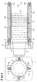
- retaining springs 35 are in addition to the multiple arrangement distributed over the circumference of retaining springs 35 between two retaining spring elements (Bolt 32 and retaining spring 35) stacking rods or guide rods 40 are provided. These are stored here - as in Fig. 2 - short retaining springs 35 and support the statically horizontally formed article rod 11 as soon as this limited area of the retaining springs 35 has left.
- the one horizontal dynamic Formation of an article rod 11 from stacked cups 10 pointing 4 has long retaining springs 135, which are effective but correspond to the short retaining springs 35 according to Figs. 2 and 3, i.e.
- the article or cup 10 is initially against the slight, radial spring tension pushed through quickly and then loosely between the recesses 34 the complementary, circumferentially distributed holding springs 135 fixed.
- retaining springs 135 are fastened directly on the guide rods 140, by means of once through the catch or stacking plate 7 and in the opposite direction from the end face in the guide rods 140 screwed bolts 41 or 42.
- the article rod 11 in the Stack channel 33 guided and supported exclusively between the retaining springs 135.
Landscapes
- Engineering & Computer Science (AREA)
- Mechanical Engineering (AREA)
- Moulds For Moulding Plastics Or The Like (AREA)
- Blow-Moulding Or Thermoforming Of Plastics Or The Like (AREA)
- Heating, Cooling, Or Curing Plastics Or The Like In General (AREA)
Abstract
Description
- Fig. 1
- in der Seitenansicht als Beispiel für eine Thermomaschine eine solche, die als Kippmaschine ausgebildet ist, mit im Ausführungsbeispiel nachgeschalteter Stapel- und Zählvorrichtung für hier gezeigte, abzustapelnde Becher, schematisch dargestellt;
- Fig. 2
- als Einzelheit in schematischer Darstellung eine Haltefeder-Anordnung zum vertikalen oder dynamischen horizontalen (wie gezeigt) Transport eines Einzelartikels;
- Fig. 3
- als Einzelheit in schematischer Darstellung eine Haltefeder-Anordnung zur statischen horizontalen (wie gezeigt) oder vertikalen Stapelbildung; und
- Fig. 4
- als Einzelheit in schematischer Darstellung eine Haltefeder-Anordnung zur dynamischen, horizontalen Stapelbildung.
Claims (6)
- Thermoformmaschine (1) zum Formen und Stanzen von tiefgezogenen, beliebigen becher- oder deckelartigen Artikeln aus thermoplastischem, über einen intermittierenden Forlientransport (2) zugeführtem Kunststoff oder dergleichen, umfassend ein mit mehreren über bzw. nebeneinanderliegenden Artikelreihen ausgebildetes Mehrfach-Form- und Stanzwerkzeug, bestehend aus einem Oberwerkzeug (26) und einem Unterwerkzeug (8), dem eine die aus der Maschine ausgestoßenen Artikel (10) übernehmende, Schieber- oder Fangplatte (7) zugeordnet ist, wobei sich der Fangplatte (7) hinter ihren die Fertigartikel (10) aufnehmenden Ausformungen (9) für jede Artikelstange (1) mindestens zwei einen Stapelkanal definierenden Führungsstangen oder dergleichen anschließen, denen federnd wirkende, dem Kanalinneren mit sägezahnartigen Ausnehmungen zugewandte Artikel-Haltemittel zugeordnet sind,
dadurch gekennzeichnet,
daß die Artikel-Haltemittel insgesamt als Haltefedern (35, 135) ausgebildet und mit einem solchen Stichmaß (39) voneinander beabstandet sind, bei dem der eingestapelte Artikel (10) lose zwischen den komplementären Ausnehmungen (34) der Haltefedern (35; 135) des jeweiligen Stapelkanals (33) aufgenommen ist. - Thermoformmaschine nach Anspruch 1,
dadurch gekennzeichnet,
daß die Haltefedern (35; 135) aus streifenartigen Federstahlbändern geformt sind. - Thermoformmaschine nach Anspruch 1 oder 2,
dadurch gekennzeichnet,
daß die Haltefedern (35) auf den Stapelkanal (33) definierenden Schraubbolzen (32) angeordnet sind. - Thermoformmaschine nach Anspruch 1 oder 2,
dadurch gekennzeichnet,
daß die Haltefedern (135) auf den Führungsstangen (140) angeordnet sind. - Thermoformmaschine nach einem der Ansprüche 1 bis 3,
gekennzeichnet durch
den mit Haltefedern (35) bestückten Schraubbolzen (32) zugeordnete Führungsstangen (40). - Thermoformmaschine nach einem der Ansprüche 1 bis 5,
dadurch gekennzeichnet,
daß die Haltefedern (35; 135) eine in Stapelrichtung zum Kanalinneren ansteigende Einlaufschräge (38) aufweisen.
Applications Claiming Priority (2)
| Application Number | Priority Date | Filing Date | Title |
|---|---|---|---|
| DE10004553A DE10004553A1 (de) | 2000-02-02 | 2000-02-02 | Thermoformmaschine |
| DE10004553 | 2000-02-02 |
Publications (2)
| Publication Number | Publication Date |
|---|---|
| EP1122196A1 true EP1122196A1 (de) | 2001-08-08 |
| EP1122196B1 EP1122196B1 (de) | 2003-09-10 |
Family
ID=7629584
Family Applications (1)
| Application Number | Title | Priority Date | Filing Date |
|---|---|---|---|
| EP00115370A Expired - Lifetime EP1122196B1 (de) | 2000-02-02 | 2000-07-15 | Thermoformmaschine |
Country Status (3)
| Country | Link |
|---|---|
| EP (1) | EP1122196B1 (de) |
| AT (1) | ATE249381T1 (de) |
| DE (2) | DE10004553A1 (de) |
Cited By (1)
| Publication number | Priority date | Publication date | Assignee | Title |
|---|---|---|---|---|
| DE10356001A1 (de) * | 2002-11-28 | 2004-06-24 | Walter Lauermann | Stapel-Übergabeverfahren, -anordnung und -vorrichtung |
Citations (5)
| Publication number | Priority date | Publication date | Assignee | Title |
|---|---|---|---|---|
| US1752607A (en) * | 1929-01-21 | 1930-04-01 | Harold A Miller | Drinking-cup dispenser |
| GB1212189A (en) * | 1966-12-27 | 1970-11-11 | Owens Illinois Inc | Apparatus and method for collecting molded articles |
| DE3624683C2 (de) | 1986-06-12 | 1989-07-13 | Officine Meccaniche Veronesi (O.M.V.) S.P.A., Parona, Verona, It | |
| EP0955150A2 (de) * | 1998-02-11 | 1999-11-10 | Gabler Maschinenbau GmbH | Stapelvorrichtung für eine Thermoformmaschine |
| DE19848627A1 (de) | 1998-10-22 | 2000-04-27 | Gabler Gmbh Maschbau | Thermoformmaschine |
-
2000
- 2000-02-02 DE DE10004553A patent/DE10004553A1/de not_active Withdrawn
- 2000-07-15 AT AT00115370T patent/ATE249381T1/de not_active IP Right Cessation
- 2000-07-15 EP EP00115370A patent/EP1122196B1/de not_active Expired - Lifetime
- 2000-07-15 DE DE50003628T patent/DE50003628D1/de not_active Expired - Lifetime
Patent Citations (5)
| Publication number | Priority date | Publication date | Assignee | Title |
|---|---|---|---|---|
| US1752607A (en) * | 1929-01-21 | 1930-04-01 | Harold A Miller | Drinking-cup dispenser |
| GB1212189A (en) * | 1966-12-27 | 1970-11-11 | Owens Illinois Inc | Apparatus and method for collecting molded articles |
| DE3624683C2 (de) | 1986-06-12 | 1989-07-13 | Officine Meccaniche Veronesi (O.M.V.) S.P.A., Parona, Verona, It | |
| EP0955150A2 (de) * | 1998-02-11 | 1999-11-10 | Gabler Maschinenbau GmbH | Stapelvorrichtung für eine Thermoformmaschine |
| DE19848627A1 (de) | 1998-10-22 | 2000-04-27 | Gabler Gmbh Maschbau | Thermoformmaschine |
Cited By (2)
| Publication number | Priority date | Publication date | Assignee | Title |
|---|---|---|---|---|
| DE10356001A1 (de) * | 2002-11-28 | 2004-06-24 | Walter Lauermann | Stapel-Übergabeverfahren, -anordnung und -vorrichtung |
| DE10356001B4 (de) * | 2002-11-28 | 2006-08-17 | Walter Lauermann | Stapel-Übergabeverfahren, -anordnung und -vorrichtung |
Also Published As
| Publication number | Publication date |
|---|---|
| DE50003628D1 (de) | 2003-10-16 |
| DE10004553A1 (de) | 2001-08-16 |
| ATE249381T1 (de) | 2003-09-15 |
| EP1122196B1 (de) | 2003-09-10 |
Similar Documents
| Publication | Publication Date | Title |
|---|---|---|
| DE3439660C2 (de) | ||
| DE3886076T3 (de) | Vorrichtung zum Herstellen von hohlen Artikeln aus Kunststoff. | |
| DE9219137U1 (de) | Thermoformmaschine zum Herstellen von hohlen Gegenständen | |
| DE4030833C2 (de) | ||
| DE69702572T2 (de) | Vorrichtung zum Entformen und Nachbehandeln von in einer Thermoformmaschine warmgeformten Gegenständen | |
| EP0955150B1 (de) | Stapelvorrichtung für eine Thermoformmaschine | |
| DE4421870A1 (de) | Stapelbarer, dünnwandiger Behälter | |
| DE60004404T2 (de) | Vorrichtung zum handhaben von vorformlingen mit einem horizontalachsigen drehturm | |
| DE69525537T2 (de) | Warmformvorrichtung zum warmformen von bandförmigen oder folienförmigen materialien | |
| DE19848627B4 (de) | Stapelvorrichtung für eine Thermoformvorrichtung | |
| DE3625841A1 (de) | Stapelvorrichtung fuer, insbesondere in einer thermoform-maschine hergestellte, kunststoff-tiefziehteile | |
| DE102005026687B4 (de) | Verfahren und Vorrichtung zum Stapeln von tiefgezogenen Artikeln | |
| DE19812414A1 (de) | Aufnahmeverfahren und -vorrichtung für Serien-Erzeugnisse, insbesondere Kunststoff-Becher | |
| DE19804876A1 (de) | Verfahren und Einrichtung zur Wärmeformung und Dekorbandanbringung | |
| EP1122196B1 (de) | Thermoformmaschine | |
| DE69327246T2 (de) | Transportvorrichtung für ein Element von einer Formeinrichtung in eine Formoperation für kleine Gegenstände | |
| DE19848628C2 (de) | Verfahren zum Betreiben einer Thermoformmaschine | |
| DE4436531C1 (de) | Verfahren zum Überführen von mehrreihig aus einer thermoplastischen Kunstoffolie geformten und ausgestanzten Artikeln in einreihige Stapel und Vorrichtung zur Durchführung des Verfahrens | |
| DE3002355C2 (de) | Käsepresse | |
| EP4186674B1 (de) | Vorrichtung zum spritzgiessen eines formteils mit einem einleger | |
| EP0995583B1 (de) | Thermoformmaschine | |
| EP2860017B1 (de) | Thermoformmaschine | |
| DE3145354A1 (de) | Verfahren zum entformen von behaeltern aus thermoplastischer kunststoffolie und vorrichtung zur durchfuehrung des verfahrens | |
| EP1570972B1 (de) | Thermoformmaschine mit Zwischenspeicher und Verfahren zum Betreiben selbiger | |
| EP1090735A2 (de) | Verfahren und Vorrichtung zum Thermoformen von Behältern |
Legal Events
| Date | Code | Title | Description |
|---|---|---|---|
| PUAI | Public reference made under article 153(3) epc to a published international application that has entered the european phase |
Free format text: ORIGINAL CODE: 0009012 |
|
| AK | Designated contracting states |
Kind code of ref document: A1 Designated state(s): AT BE CH CY DE DK ES FI FR GB GR IE IT LI LU MC NL PT SE |
|
| AX | Request for extension of the european patent |
Free format text: AL;LT;LV;MK;RO;SI |
|
| 17P | Request for examination filed |
Effective date: 20020122 |
|
| AKX | Designation fees paid |
Free format text: AT BE CH CY DE DK ES FI FR GB GR IE IT LI LU MC NL PT SE |
|
| GRAH | Despatch of communication of intention to grant a patent |
Free format text: ORIGINAL CODE: EPIDOS IGRA |
|
| GRAH | Despatch of communication of intention to grant a patent |
Free format text: ORIGINAL CODE: EPIDOS IGRA |
|
| GRAA | (expected) grant |
Free format text: ORIGINAL CODE: 0009210 |
|
| AK | Designated contracting states |
Kind code of ref document: B1 Designated state(s): AT BE CH CY DE DK ES FI FR GB GR IE IT LI LU MC NL PT SE |
|
| PG25 | Lapsed in a contracting state [announced via postgrant information from national office to epo] |
Ref country code: IE Free format text: LAPSE BECAUSE OF FAILURE TO SUBMIT A TRANSLATION OF THE DESCRIPTION OR TO PAY THE FEE WITHIN THE PRESCRIBED TIME-LIMIT Effective date: 20030910 Ref country code: FI Free format text: LAPSE BECAUSE OF FAILURE TO SUBMIT A TRANSLATION OF THE DESCRIPTION OR TO PAY THE FEE WITHIN THE PRESCRIBED TIME-LIMIT Effective date: 20030910 Ref country code: CY Free format text: LAPSE BECAUSE OF FAILURE TO SUBMIT A TRANSLATION OF THE DESCRIPTION OR TO PAY THE FEE WITHIN THE PRESCRIBED TIME-LIMIT Effective date: 20030910 Ref country code: ES Free format text: LAPSE BECAUSE OF FAILURE TO SUBMIT A TRANSLATION OF THE DESCRIPTION OR TO PAY THE FEE WITHIN THE PRESCRIBED TIME-LIMIT Effective date: 20030910 Ref country code: GB Free format text: LAPSE BECAUSE OF FAILURE TO SUBMIT A TRANSLATION OF THE DESCRIPTION OR TO PAY THE FEE WITHIN THE PRESCRIBED TIME-LIMIT Effective date: 20030910 Ref country code: FR Free format text: LAPSE BECAUSE OF FAILURE TO SUBMIT A TRANSLATION OF THE DESCRIPTION OR TO PAY THE FEE WITHIN THE PRESCRIBED TIME-LIMIT Effective date: 20030910 |
|
| REG | Reference to a national code |
Ref country code: GB Ref legal event code: FG4D Free format text: NOT ENGLISH |
|
| REG | Reference to a national code |
Ref country code: CH Ref legal event code: EP |
|
| REF | Corresponds to: |
Ref document number: 50003628 Country of ref document: DE Date of ref document: 20031016 Kind code of ref document: P |
|
| REG | Reference to a national code |
Ref country code: IE Ref legal event code: FG4D Free format text: GERMAN |
|
| PG25 | Lapsed in a contracting state [announced via postgrant information from national office to epo] |
Ref country code: GR Free format text: LAPSE BECAUSE OF FAILURE TO SUBMIT A TRANSLATION OF THE DESCRIPTION OR TO PAY THE FEE WITHIN THE PRESCRIBED TIME-LIMIT Effective date: 20031210 Ref country code: SE Free format text: LAPSE BECAUSE OF FAILURE TO SUBMIT A TRANSLATION OF THE DESCRIPTION OR TO PAY THE FEE WITHIN THE PRESCRIBED TIME-LIMIT Effective date: 20031210 Ref country code: DK Free format text: LAPSE BECAUSE OF FAILURE TO SUBMIT A TRANSLATION OF THE DESCRIPTION OR TO PAY THE FEE WITHIN THE PRESCRIBED TIME-LIMIT Effective date: 20031210 |
|
| PG25 | Lapsed in a contracting state [announced via postgrant information from national office to epo] |
Ref country code: PT Free format text: LAPSE BECAUSE OF FAILURE TO SUBMIT A TRANSLATION OF THE DESCRIPTION OR TO PAY THE FEE WITHIN THE PRESCRIBED TIME-LIMIT Effective date: 20031219 |
|
| GBV | Gb: ep patent (uk) treated as always having been void in accordance with gb section 77(7)/1977 [no translation filed] |
Effective date: 20030910 |
|
| REG | Reference to a national code |
Ref country code: IE Ref legal event code: FD4D |
|
| PG25 | Lapsed in a contracting state [announced via postgrant information from national office to epo] |
Ref country code: LU Free format text: LAPSE BECAUSE OF NON-PAYMENT OF DUE FEES Effective date: 20040715 |
|
| PLBE | No opposition filed within time limit |
Free format text: ORIGINAL CODE: 0009261 |
|
| STAA | Information on the status of an ep patent application or granted ep patent |
Free format text: STATUS: NO OPPOSITION FILED WITHIN TIME LIMIT |
|
| PG25 | Lapsed in a contracting state [announced via postgrant information from national office to epo] |
Ref country code: MC Free format text: LAPSE BECAUSE OF NON-PAYMENT OF DUE FEES Effective date: 20040731 Ref country code: LI Free format text: LAPSE BECAUSE OF NON-PAYMENT OF DUE FEES Effective date: 20040731 Ref country code: CH Free format text: LAPSE BECAUSE OF NON-PAYMENT OF DUE FEES Effective date: 20040731 Ref country code: BE Free format text: LAPSE BECAUSE OF NON-PAYMENT OF DUE FEES Effective date: 20040731 |
|
| 26N | No opposition filed |
Effective date: 20040614 |
|
| EN | Fr: translation not filed | ||
| BERE | Be: lapsed |
Owner name: *GABLER MASCHINENBAU G.M.B.H. Effective date: 20040731 |
|
| REG | Reference to a national code |
Ref country code: CH Ref legal event code: PL |
|
| BERE | Be: lapsed |
Owner name: *GABLER MASCHINENBAU G.M.B.H. Effective date: 20040731 |
|
| PGFP | Annual fee paid to national office [announced via postgrant information from national office to epo] |
Ref country code: NL Payment date: 20100714 Year of fee payment: 11 |
|
| PGFP | Annual fee paid to national office [announced via postgrant information from national office to epo] |
Ref country code: DE Payment date: 20100723 Year of fee payment: 11 Ref country code: IT Payment date: 20100726 Year of fee payment: 11 Ref country code: AT Payment date: 20100714 Year of fee payment: 11 |
|
| REG | Reference to a national code |
Ref country code: NL Ref legal event code: V1 Effective date: 20120201 |
|
| REG | Reference to a national code |
Ref country code: AT Ref legal event code: MM01 Ref document number: 249381 Country of ref document: AT Kind code of ref document: T Effective date: 20110715 |
|
| PG25 | Lapsed in a contracting state [announced via postgrant information from national office to epo] |
Ref country code: DE Free format text: LAPSE BECAUSE OF NON-PAYMENT OF DUE FEES Effective date: 20120201 |
|
| REG | Reference to a national code |
Ref country code: DE Ref legal event code: R119 Ref document number: 50003628 Country of ref document: DE Effective date: 20120201 |
|
| PG25 | Lapsed in a contracting state [announced via postgrant information from national office to epo] |
Ref country code: NL Free format text: LAPSE BECAUSE OF NON-PAYMENT OF DUE FEES Effective date: 20120201 Ref country code: IT Free format text: LAPSE BECAUSE OF NON-PAYMENT OF DUE FEES Effective date: 20110715 |
|
| PG25 | Lapsed in a contracting state [announced via postgrant information from national office to epo] |
Ref country code: AT Free format text: LAPSE BECAUSE OF NON-PAYMENT OF DUE FEES Effective date: 20110715 |