EP1122212A2 - Nanostrukturierte Teilchen bestehend aus Russ und pyrogene Kieselsäure enthaltendem Kompositmaterial - Google Patents
Nanostrukturierte Teilchen bestehend aus Russ und pyrogene Kieselsäure enthaltendem Kompositmaterial Download PDFInfo
- Publication number
- EP1122212A2 EP1122212A2 EP00106229A EP00106229A EP1122212A2 EP 1122212 A2 EP1122212 A2 EP 1122212A2 EP 00106229 A EP00106229 A EP 00106229A EP 00106229 A EP00106229 A EP 00106229A EP 1122212 A2 EP1122212 A2 EP 1122212A2
- Authority
- EP
- European Patent Office
- Prior art keywords
- flame
- silica
- hmdso
- particles
- hydrogen
- Prior art date
- Legal status (The legal status is an assumption and is not a legal conclusion. Google has not performed a legal analysis and makes no representation as to the accuracy of the status listed.)
- Granted
Links
Images




Classifications
-
- B—PERFORMING OPERATIONS; TRANSPORTING
- B82—NANOTECHNOLOGY
- B82Y—SPECIFIC USES OR APPLICATIONS OF NANOSTRUCTURES; MEASUREMENT OR ANALYSIS OF NANOSTRUCTURES; MANUFACTURE OR TREATMENT OF NANOSTRUCTURES
- B82Y30/00—Nanotechnology for materials or surface science, e.g. nanocomposites
-
- C—CHEMISTRY; METALLURGY
- C01—INORGANIC CHEMISTRY
- C01B—NON-METALLIC ELEMENTS; COMPOUNDS THEREOF; METALLOIDS OR COMPOUNDS THEREOF NOT COVERED BY SUBCLASS C01C
- C01B33/00—Silicon; Compounds thereof
- C01B33/113—Silicon oxides; Hydrates thereof
- C01B33/12—Silica; Hydrates thereof, e.g. lepidoic silicic acid
- C01B33/18—Preparation of finely divided silica neither in sol nor in gel form; After-treatment thereof
- C01B33/181—Preparation of finely divided silica neither in sol nor in gel form; After-treatment thereof by a dry process
- C01B33/183—Preparation of finely divided silica neither in sol nor in gel form; After-treatment thereof by a dry process by oxidation or hydrolysis in the vapour phase of silicon compounds such as halides, trichlorosilane, monosilane
-
- C—CHEMISTRY; METALLURGY
- C08—ORGANIC MACROMOLECULAR COMPOUNDS; THEIR PREPARATION OR CHEMICAL WORKING-UP; COMPOSITIONS BASED THEREON
- C08K—Use of inorganic or non-macromolecular organic substances as compounding ingredients
- C08K3/00—Use of inorganic substances as compounding ingredients
- C08K3/02—Elements
- C08K3/04—Carbon
-
- C—CHEMISTRY; METALLURGY
- C08—ORGANIC MACROMOLECULAR COMPOUNDS; THEIR PREPARATION OR CHEMICAL WORKING-UP; COMPOSITIONS BASED THEREON
- C08K—Use of inorganic or non-macromolecular organic substances as compounding ingredients
- C08K3/00—Use of inorganic substances as compounding ingredients
- C08K3/34—Silicon-containing compounds
- C08K3/36—Silica
-
- C—CHEMISTRY; METALLURGY
- C09—DYES; PAINTS; POLISHES; NATURAL RESINS; ADHESIVES; COMPOSITIONS NOT OTHERWISE PROVIDED FOR; APPLICATIONS OF MATERIALS NOT OTHERWISE PROVIDED FOR
- C09C—TREATMENT OF INORGANIC MATERIALS, OTHER THAN FIBROUS FILLERS, TO ENHANCE THEIR PIGMENTING OR FILLING PROPERTIES ; PREPARATION OF CARBON BLACK ; PREPARATION OF INORGANIC MATERIALS WHICH ARE NO SINGLE CHEMICAL COMPOUNDS AND WHICH ARE MAINLY USED AS PIGMENTS OR FILLERS
- C09C1/00—Treatment of specific inorganic materials other than fibrous fillers; Preparation of carbon black
- C09C1/28—Compounds of silicon
- C09C1/30—Silicic acid
- C09C1/3045—Treatment with inorganic compounds
-
- C—CHEMISTRY; METALLURGY
- C09—DYES; PAINTS; POLISHES; NATURAL RESINS; ADHESIVES; COMPOSITIONS NOT OTHERWISE PROVIDED FOR; APPLICATIONS OF MATERIALS NOT OTHERWISE PROVIDED FOR
- C09C—TREATMENT OF INORGANIC MATERIALS, OTHER THAN FIBROUS FILLERS, TO ENHANCE THEIR PIGMENTING OR FILLING PROPERTIES ; PREPARATION OF CARBON BLACK ; PREPARATION OF INORGANIC MATERIALS WHICH ARE NO SINGLE CHEMICAL COMPOUNDS AND WHICH ARE MAINLY USED AS PIGMENTS OR FILLERS
- C09C1/00—Treatment of specific inorganic materials other than fibrous fillers; Preparation of carbon black
- C09C1/44—Carbon
- C09C1/48—Carbon black
-
- C—CHEMISTRY; METALLURGY
- C01—INORGANIC CHEMISTRY
- C01P—INDEXING SCHEME RELATING TO STRUCTURAL AND PHYSICAL ASPECTS OF SOLID INORGANIC COMPOUNDS
- C01P2002/00—Crystal-structural characteristics
- C01P2002/80—Crystal-structural characteristics defined by measured data other than those specified in group C01P2002/70
- C01P2002/88—Crystal-structural characteristics defined by measured data other than those specified in group C01P2002/70 by thermal analysis data, e.g. TGA, DTA, DSC
-
- C—CHEMISTRY; METALLURGY
- C01—INORGANIC CHEMISTRY
- C01P—INDEXING SCHEME RELATING TO STRUCTURAL AND PHYSICAL ASPECTS OF SOLID INORGANIC COMPOUNDS
- C01P2004/00—Particle morphology
- C01P2004/01—Particle morphology depicted by an image
- C01P2004/04—Particle morphology depicted by an image obtained by TEM, STEM, STM or AFM
-
- C—CHEMISTRY; METALLURGY
- C01—INORGANIC CHEMISTRY
- C01P—INDEXING SCHEME RELATING TO STRUCTURAL AND PHYSICAL ASPECTS OF SOLID INORGANIC COMPOUNDS
- C01P2004/00—Particle morphology
- C01P2004/30—Particle morphology extending in three dimensions
- C01P2004/32—Spheres
-
- C—CHEMISTRY; METALLURGY
- C01—INORGANIC CHEMISTRY
- C01P—INDEXING SCHEME RELATING TO STRUCTURAL AND PHYSICAL ASPECTS OF SOLID INORGANIC COMPOUNDS
- C01P2004/00—Particle morphology
- C01P2004/60—Particles characterised by their size
- C01P2004/64—Nanometer sized, i.e. from 1-100 nanometer
-
- C—CHEMISTRY; METALLURGY
- C01—INORGANIC CHEMISTRY
- C01P—INDEXING SCHEME RELATING TO STRUCTURAL AND PHYSICAL ASPECTS OF SOLID INORGANIC COMPOUNDS
- C01P2006/00—Physical properties of inorganic compounds
- C01P2006/10—Solid density
-
- C—CHEMISTRY; METALLURGY
- C01—INORGANIC CHEMISTRY
- C01P—INDEXING SCHEME RELATING TO STRUCTURAL AND PHYSICAL ASPECTS OF SOLID INORGANIC COMPOUNDS
- C01P2006/00—Physical properties of inorganic compounds
- C01P2006/12—Surface area
-
- C—CHEMISTRY; METALLURGY
- C01—INORGANIC CHEMISTRY
- C01P—INDEXING SCHEME RELATING TO STRUCTURAL AND PHYSICAL ASPECTS OF SOLID INORGANIC COMPOUNDS
- C01P2006/00—Physical properties of inorganic compounds
- C01P2006/80—Compositional purity
Definitions
- silica Although flame synthesis for silica was established since 1943 when Aerosil was produced (Hartmann et al., 1989), its fundamentals are not yet well understood as the particle formation and growth take place extremely fast (less than a second) and process parameters are coupled. Fumed silica was developed as a substitute for carbon black. It is formed by the combustion of silicon tetrachloride or some other silicon containing compound with a hydrogencontaining fuel and air.
- Kammler and Pratsinis studied the synthesis of silica at rather large production rates (more than 100 g/h) using also HMDSO as silica source. They introduced a particle collection system containing a NOMEX baghouse filter, while the use of HMDSO or other organimetallic compounds had the advantage over SiCl4 that they do not produce the corrosive by-products HCl and Cl 2 .
- a goal of this study was to investigate the possibility for control of the product particle size at in a Pilot-scale aerosol flame reactor, using a collection system in which there is no limitation in production time.
- the subject of the invention are composite carbon black-fumed silica nanostructured paricles comprising a surface area 30 to 400 m 2 /g a carbon content 0,1 to 10 weight % grind readings lower than 30 homogeneously distributed carbon throughout the silica, but no isolated carbon particles.
- a further subject of the invention is a method to produce the composite carbon black-fumed silica nanostructured particles characterized in that organic metallic compounds, especially Helamethyldisoloxan, are burned in flame of hydrogen and air.
- the composite carbon black-furmed silica nanostructured particles according to this invention can be used as filler for rubber and/or Silicon rubber mixtures.
- FIG. 1 shows a schematic of the experimental set-up of the large scale flame reactor unit.
- the silica precursor hexamethyldisiloxane is delivered by bubbling clean dry nitrogen gas through a fritted cylinder, placed into a 2 L Woulffian flask 1 filled up to 3 ⁇ 4 with HMDSO.
- Fresh HMDSO could be supplied continuously into the Woulffian flask 1 by a gear pump 2 from a second flask 3 in order to maintain a constant level of liquid HMDSO to keep constant the saturation of the carrier gas even at the highest production rates.
- the Woulffian flask 1 is stored in a thermostated bath to provide a defined stable HMDSO flask temperature during the experiment.
- the gases are metered by calibrated mass flow controllers and rotameters.
- a 30 cm long Allihn-condenser 5 is installed between the burner 4 and the HMDSO flask 1.
- the cooling chamber of the condenser is filled with water which is heated by heating and the exit is filled with glass wool in order to prevent entrainment of small HMDSO droplets into the burner.
- the tubing between flask and burner is heated at minimum 40 K higher than the HMDSO.
- the dimensions of the burner are given in Figure 2.
- One of the main tasks was to design a burner which is able to produce silica particles at high production rate. Therefore, the air delivering tube (tube 4) had to be designed larger than the other tubes not to create supersonic velocities in the burner, as it was planned to provide an excess of oxygen for combustion.
- the HMDSO-laden nitrogen stream is fed through the first (center) tube.
- Hydrogen is supplied through second and third tube. Using this configuration the hydrogen acts as shield gas at the burner exit slowing down the oxidation of the precursor right on the burner tip and prevent particle deposition there.
- the flame is ignited with a spark plug positioned vertical to the burner, which is removed after the ignition to avoid disturbances of the flame. Disturbtion of the flame is prevented by using a steel chimney 6 ( Figure 1) which is open on top and avoids air entrainment into the lower part of the burning zone
- pneumatic ball valves are installed between the mass flow controllers and the burner. These nitrogen pressured ball valves open when another electro-pneumatic ball valve opens the nitrogen reservoir. These valves are closed when the energy supply either electricity or pressurized nitrogen supply is interrupted. Additional, check valves are installed right before the gases enter the burner to avoid backflow of the gases.
- the whole piping was designed to withstand explosions.
- the gas pressure reduction of air and hydrogen is made in two stages: from 200 bar (gas cylinder) to 25 bar and from 25 to 8 bar, which is close to the operating pressure for the mass flow controllers (6.5 bar) as the gas pressure is crucial for maintaining constant mass flow rates.
- the electronic control permits remote valve control, ignition with the spark plug and fast shut-down in case of any operational problems.
- the control can automatically shut down the flame reactor.
- the hydrogen and air supply line delivering the gas from the gas cylinders to the flow controllers is fitted with mechanical safety valves that are connected to the vent.
- the opening pressure is adjusted to 25 bar.
- the particle collection unit consists of a commercial ,,Jet filter 7.
- Four PTFE (polytetrafouroethylene, Teflon) coated Nomex baghouse filters collect the powder.
- the filters are set in a stainless steel filter house which has an inlet 0.6 m long 0.12 m diameter pipe with a cone at its open end ( Figure 1).
- the particles are collected on the outside of the baghouse filters by an air suction ventilator which is controlled by a frequency transducer.
- the particles are removed periodically (every 70 sec) from the baghouse filters by air pressure shocks (timing pulse: 30-300 ms) using 5 bars absolute pressure.
- the product particles drop into a removable container that is placed at the lower part of the filter house.
- the air-number is defined as the relative value of the effective (actual) amount of fuel (hydrogen and HMDSO) to oxidant to the stochiometric amount of fuel to oxidant and is the inverse value of the equivalence ratio although air-numbers are most useful for premixed flames.
- the HMDSO-concentration is calculated gravimetrically, while the flask temperature is measured by an R-Type thermocouple (Thermoax) and a thermometer. Also the outside wall temperature of the heated manifold and the filter-in-and outlet gas stream temperatures are measured with a thermocouples. They are monitored on a personal computer using LabVIEW software. From the gravimetric measurements, the saturation is calculated by a mass balance for the precursor flask, using the HMDSO equilibrium vapor pressure. The flame location and height are determined visually. Here, the length of the flame is defined as the distance between the beginning and the end of the luminous zone.
- the specific surface area with respect to mass, As, of the SiO 2 -particles is measured by nitrogen at 77.3 K. Before the adsorption, the samples are under nitrogen atmosphere at 150 °C for two hours, to remove H 2 O molecules that are bound to the particle surface from the air moisture.
- This diameter corresponds to the primary particles in the aggregate particles but will be slightly larger than the diameter determined by microscopic analysis since BET analysis does not account for the area lost between the joined primary particles in aggregates. All powders are reproduced at least twice and the specific surface area also is measured twice or thrice for each sample in order to minimize the errors in particle analysis. Data points are averages of these results while the error bars show two times the corresponding standard deviation.
- the soot fraction of the collected powders was determined by thermogravimetric analysis.
- the powders were heated up from room temperature to 105°C, held at this temperature for 2 h, then heated to 600°C (10°C/min) all under nitrogen atmosphere and then further heated up to 1000°C under oxygen atmosphere using always heating rates of 10°C/min. Then the powder remained for 1 h at this final temperature.
- thermocouples (Moser AG). Measuring the flame temperature in a particle laden flame with a thermocouple at these HMDSO concentrations leads to considerable deposition on the tip of the thermocouple. Therefore, the thermocouples are cleaned carefully after each measurement. The flame temperatures are corrected for radiation loss according to Collis and Williams (1959).
- Producing 300 g/h SiO 2 , 38% of the total thermal input of the flame is delivered by hydrogen when adding 16.2 L/min H 2 , while 65% is supported by H 2 when 48.6 L/min are added.
- the total energy of combustion increases from 6.5 to 11 kW.
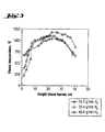
- Figure 3 shows axial flame temperatures measured along the center line with an R-Type thermocouple in the particle laden flame for a production rate of 300 g/h SiO 2 and an air flow rate of 120 L/min.
- Increasing the hydrogen flow from 16.2 to 48.6 L/min increases the maximum flame temperature from 1080 to 1170°C.
- the flame temperatures in first centimeters of the flame decrease with increasing hydrogen flow rate indicating that the hydrogen cools the flame there as the reaction is diffusion limited.
- These flame temperatures can give only a qualitative idea of the real flame temperature as particle deposition takes place on the tip of the thermocouple. Therefore, the measured flame temperatures may be too low due to the layer of particles on the thermocouple.
- Figure 4 shows the influence of the hydrogen flow rate on the specific surface area of the product powder for production rates of 300 g/h and an air flow rate of 120 L/min.
- the dashed line is the bestfit line of the experimental data, also as in all following figures.
- Increasing the hydrogen flow rate from 16.2 to 56.7 L/min decreases the specific surface area 131 to 96 m 2 /g while the primary particle diameter is increased from 21 to 28 nm, respectively.
- Due to the higher flame temperatures (Figure 3) the sintering rate of the particles increases and therefore the particle growth is accelerated, hence, larger particles are formed.
- Transmission electron micrographs are corresponding to Figure 4 are given in Figure 5.
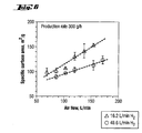
- Figure 6 shows the specific surface area, As, as a function of the air flow rate for two hydrogen flow rates at production rates of 300 g/h.
- 16.2 L/min (triangles) of hydrogen the specific surface area of the product powder is increased from 99 to 154 m 2 /g when increasing the air flow rate from 69 to 154 L/min. Assuming no surrounding air would be entrained into the flame, this corresponds to an increase of the air-number from 0.9 to 1.9, respectively, and the burner exit velocity in the air tube increases from 6.7 to 15.1 m/s.
- 48.6 L/min hydrogen squares the specific surface area decreases also almost linearly though the influence of the air flow rate is less significant than for 16.2 L/min (triangles).
- the average primary particle diameter of the powder is reduced from 31 to 22 nm, while the specific surface area increases from 89 to 124 m 2 /g when the air flow rate is increased from 85.6 to 171.2 L/min.
- the air-number increases from 0./ to 1.3.
- the flame height is reduced from 55 to 35 cm increasing the air flow rate from 85.6 to 154.1 L/min and from 50 to 40 cm for 16.2 and 48.6 L/min hydrogen, respectively. This is in agreement to Briesen et al. (1998) who observed a decrease of the flame height of an HMDSO doped methane/air diffusion flame from 7.5 to 5 cm (Briesen, 1997) increasing the total oxidant flow from 2.5 to 5.5 L/min.
- the specific surface area increased from 170 to 230 m 2 /g (Briesen et al., 1998). With increasing air flow rate the residence time of the particles in the flame is reduced due to the reduction of the flame height and therefore there is less time to grow and therefore smaller particles are formed. Increasing the air flow rate reduces the flame height and residence time, and subsequently, may reduce the oxidation rate of HMDSO and the yield of the process (Pratsinis et al., 1990). Also the flame temperature is reduced as more air has to be heated up leading to slower growth processes due to sintering and as a result the average primary particle size is also reduced. Using more fuel the flame temperature increases (Figure 3) leading to larger particles as a result of the enhanced growth process and faster sintering.
- the specific surface area of the powders using 16.2 L/min hydrogen is influenced more significant by increasing the air flow rate than powders produced with 48.6 L/min hydrogen (circles) as the total energy per mol SiO 2 is significantly larger for the latter powders (4470 and 7858 kJ/mol SiO2). Hence, adding air does not dilute the flame in this case.
- Figure 8 shows the weight loss determined by thermogravimetric analysis reduced for the weight loss of the powders from 30 to 105°C which was attributed to the water vapor sitting on the particle surface. Here it is visible that even white powders loose very little weight indicating some small impurities or removal of crystal-water from the powders. However, comparing the white powders to the commercial powder (Aerosil 200), TGA-analysis shows good agreement.
- Figure 1 Experimental set-up for the production of SiO 2 and SiO 2 -C from HMDSO.
- FIG. 1 Drawing of the used diffusion burner.
- Figure 3 Axial temperature profile along the center line of the particle laden flame for production rates of 300 g/h. The temperatures are corrected by radiation loss according to Collis and Williams (1959).
- Figure 4 Specific surface area As at production rates of 300 g/h as a function of the hydrogen flow rate.
- Figure 5 TEM pictures (will be included).
- Figure 6 Specific surface area As at production rates of 300 g/h as a function of the air flow rate for hydrogen flow rates of 16.2 L/min (triangles) and 48.6 L/min (circles).
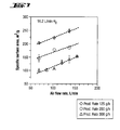
- Figure 7 Specific surface area As as a function of the air flow rate for production rates of 125 g/h (diamonds), 200 g/h (circles), and 300 g/h (triangles).
- the air flow rate and the hydrogen flow rate were constant at 120 L/min and 16.2 L/min, respectively.
- Figure 7 Specific surface area As as a function of the air flow rate for production rates of 125 g/h (diamonds), 200 g/h (circles), and 300 g/h (triangles).
- the air flow rate and the hydrogen flow rate were constant at 120 L/min and 16.2 L/min, respectively.
- Figure 8 Soot content of powders collected on the baghouse filter measured with thermogravimetric analysis as a function of the hydrogen flow rate. These data correlate to the data shown in Figures 4.
Landscapes
- Chemical & Material Sciences (AREA)
- Organic Chemistry (AREA)
- Engineering & Computer Science (AREA)
- Polymers & Plastics (AREA)
- Health & Medical Sciences (AREA)
- Medicinal Chemistry (AREA)
- Chemical Kinetics & Catalysis (AREA)
- Nanotechnology (AREA)
- Inorganic Chemistry (AREA)
- Physics & Mathematics (AREA)
- Composite Materials (AREA)
- Condensed Matter Physics & Semiconductors (AREA)
- General Physics & Mathematics (AREA)
- Materials Engineering (AREA)
- Crystallography & Structural Chemistry (AREA)
- Silicon Compounds (AREA)
Priority Applications (2)
| Application Number | Priority Date | Filing Date | Title |
|---|---|---|---|
| DE2000603778 DE60003778T2 (de) | 2000-03-22 | 2000-03-22 | Nanostrukturierte Teilchen bestehend aus Russ und pyrogene Kieselsäure enthaltendem Kompositmaterial |
| AT00106229T ATE244682T1 (de) | 2000-03-22 | 2000-03-22 | Nanostrukturierte teilchen bestehend aus russ und pyrogene kieselsäure enthaltendem kompositmaterial |
Applications Claiming Priority (2)
| Application Number | Priority Date | Filing Date | Title |
|---|---|---|---|
| DE19954262 | 1999-11-11 | ||
| DE19954262 | 1999-11-11 |
Publications (3)
| Publication Number | Publication Date |
|---|---|
| EP1122212A2 true EP1122212A2 (de) | 2001-08-08 |
| EP1122212A3 EP1122212A3 (de) | 2002-01-09 |
| EP1122212B1 EP1122212B1 (de) | 2003-07-09 |
Family
ID=7928678
Family Applications (1)
| Application Number | Title | Priority Date | Filing Date |
|---|---|---|---|
| EP20000106229 Expired - Lifetime EP1122212B1 (de) | 1999-11-11 | 2000-03-22 | Nanostrukturierte Teilchen bestehend aus Russ und pyrogene Kieselsäure enthaltendem Kompositmaterial |
Country Status (1)
| Country | Link |
|---|---|
| EP (1) | EP1122212B1 (de) |
Cited By (9)
| Publication number | Priority date | Publication date | Assignee | Title |
|---|---|---|---|---|
| US6652612B2 (en) * | 2001-11-15 | 2003-11-25 | Catalysts & Chemicals Industries Co., Ltd. | Silica particles for polishing and a polishing agent |
| KR100818036B1 (ko) * | 2007-01-23 | 2008-03-31 | 야스히로 모리 | 복합수지의 개질방법 |
| US8097233B2 (en) | 2007-02-02 | 2012-01-17 | Commissariat A L'energie Atomique | Synthesis of nanoparticles by laser pyrolysis |
| EP2407428A2 (de) | 2010-07-12 | 2012-01-18 | Tata Consultancy Services Limited | System zur Optimierung und Kontrolle der Partikelgrößenverteilung und für das Scale-up der Nanopartikelproduktion in einem Aerosolflammenreaktor |
| CN108760589A (zh) * | 2018-05-31 | 2018-11-06 | 安徽工业大学 | 一种碳氢燃料层流火焰中碳烟采集系统及粒径分析方法 |
| CN110371990A (zh) * | 2019-07-02 | 2019-10-25 | 新疆晶硕新材料有限公司 | 一种生产气相二氧化硅的水解炉及系统 |
| WO2021164102A1 (zh) * | 2020-02-20 | 2021-08-26 | 广州汇富研究院有限公司 | 气相二氧化硅的表面改性联合处理装置和方法 |
| EP4067306A1 (de) * | 2021-03-26 | 2022-10-05 | Apollo Tyres Ltd. | Verfahren zum herstellen eines mit kieselsäure eingebetteten verbundkörpers aus russ und so hergestelltes zusammengesetztes aggregat |
| EP4486693A4 (de) * | 2022-03-04 | 2026-03-04 | Nabors Energy Transition Solutions Llc | Siliciumdioxiddotiertes kohlenstoffbasiertes nanomaterial und verfahren zur formung davon |
Family Cites Families (4)
| Publication number | Priority date | Publication date | Assignee | Title |
|---|---|---|---|---|
| DE2909815C2 (de) * | 1979-03-13 | 1984-11-22 | Wacker-Chemie GmbH, 8000 München | Verfahren zur Herstellung von hochdispersem Siliciumdioxid |
| DE3016010C2 (de) * | 1980-04-25 | 1985-01-10 | Degussa Ag, 6000 Frankfurt | Verfahren zur pyrogenen Herstellung von Kieselsäure |
| US5340560A (en) * | 1993-04-30 | 1994-08-23 | General Electric Company | Method for making fumed silica having a reduced aggregate size and product |
| US6160047A (en) * | 1997-09-26 | 2000-12-12 | The Goodyear Tire & Rubber Company | Rubber composition and tire having tread thereof |
-
2000
- 2000-03-22 EP EP20000106229 patent/EP1122212B1/de not_active Expired - Lifetime
Cited By (10)
| Publication number | Priority date | Publication date | Assignee | Title |
|---|---|---|---|---|
| US6652612B2 (en) * | 2001-11-15 | 2003-11-25 | Catalysts & Chemicals Industries Co., Ltd. | Silica particles for polishing and a polishing agent |
| KR100818036B1 (ko) * | 2007-01-23 | 2008-03-31 | 야스히로 모리 | 복합수지의 개질방법 |
| US8097233B2 (en) | 2007-02-02 | 2012-01-17 | Commissariat A L'energie Atomique | Synthesis of nanoparticles by laser pyrolysis |
| EP2407428A2 (de) | 2010-07-12 | 2012-01-18 | Tata Consultancy Services Limited | System zur Optimierung und Kontrolle der Partikelgrößenverteilung und für das Scale-up der Nanopartikelproduktion in einem Aerosolflammenreaktor |
| CN108760589A (zh) * | 2018-05-31 | 2018-11-06 | 安徽工业大学 | 一种碳氢燃料层流火焰中碳烟采集系统及粒径分析方法 |
| CN110371990A (zh) * | 2019-07-02 | 2019-10-25 | 新疆晶硕新材料有限公司 | 一种生产气相二氧化硅的水解炉及系统 |
| WO2021164102A1 (zh) * | 2020-02-20 | 2021-08-26 | 广州汇富研究院有限公司 | 气相二氧化硅的表面改性联合处理装置和方法 |
| US12234361B2 (en) | 2020-02-20 | 2025-02-25 | Guangzhou Huifu Research Institute Co., Ltd. | Combined treatment device and method for surface modification of fumed silica |
| EP4067306A1 (de) * | 2021-03-26 | 2022-10-05 | Apollo Tyres Ltd. | Verfahren zum herstellen eines mit kieselsäure eingebetteten verbundkörpers aus russ und so hergestelltes zusammengesetztes aggregat |
| EP4486693A4 (de) * | 2022-03-04 | 2026-03-04 | Nabors Energy Transition Solutions Llc | Siliciumdioxiddotiertes kohlenstoffbasiertes nanomaterial und verfahren zur formung davon |
Also Published As
| Publication number | Publication date |
|---|---|
| EP1122212A3 (de) | 2002-01-09 |
| EP1122212B1 (de) | 2003-07-09 |
Similar Documents
| Publication | Publication Date | Title |
|---|---|---|
| Kammler et al. | Synthesis of silica‐carbon particles in a turbulent H2‐air flame aerosol reactor | |
| Briesen et al. | The effect of precursor in flame synthesis of SiO2 | |
| JP6927643B2 (ja) | 吊り下げ式焼結坩堝内での石英ガラス体の調製 | |
| JP7044454B2 (ja) | 石英ガラス調製時の中間体としての炭素ドープ二酸化ケイ素造粒体の調製 | |
| JP6927642B2 (ja) | 二酸化ケイ素粉末からの石英ガラス体の調製 | |
| JP6981710B2 (ja) | 二酸化ケイ素造粒体からの石英ガラス体の調製 | |
| JP6912098B2 (ja) | 二酸化ケイ素造粒体の炭素含有量の低減および石英ガラス体の調製 | |
| EP1122212B1 (de) | Nanostrukturierte Teilchen bestehend aus Russ und pyrogene Kieselsäure enthaltendem Kompositmaterial | |
| JP6080861B2 (ja) | スート法に従って合成石英ガラスを製造する方法 | |
| JP6940235B2 (ja) | 高融点金属の溶融坩堝内での石英ガラス体の調製 | |
| US20200123039A1 (en) | Preparation of a quartz glass body | |
| US9061935B2 (en) | Method for producing synthetic quartz glass | |
| US20190062193A1 (en) | Preparation of a quartz glass body in a multi-chamber oven | |
| Jang | Experimental study of synthesis of silica nanoparticles by a bench-scale diffusion flame reactor | |
| CN102583977A (zh) | 一种间接合成石英玻璃的方法及其专用设备以及一种石英玻璃 | |
| US7910081B2 (en) | Process for the production of fumed silica | |
| JP2015504408A5 (de) | ||
| TW201738188A (zh) | 利用在熔爐中之露點監測製備石英玻璃體 | |
| JPH10212118A (ja) | 熱分解法酸化物の製法、その種の酸化物及びその使用 | |
| Chagger et al. | The formation of SiO2 from hexamethyldisiloxane combustion in counterflow methane-air flames | |
| Kammler et al. | Scaling-up the production of nanosized SiO2-particles in a double diffusion flame aerosol reactor | |
| SE431196B (sv) | Sett att genom hydrolys av kiseltetrafluorid i en laga framstella finfordelad kiseloxid | |
| Friedlander | Synthesis of nanoparticles and their agglomerates: aerosol reactors | |
| Wooldridge et al. | Demonstration of gas-phase combustion synthesis of nanosized particles using a hybrid burner | |
| Xie et al. | Synthesis of TiO2 nanoparticles by propane/air turbulent flame CVD process |
Legal Events
| Date | Code | Title | Description |
|---|---|---|---|
| PUAI | Public reference made under article 153(3) epc to a published international application that has entered the european phase |
Free format text: ORIGINAL CODE: 0009012 |
|
| AK | Designated contracting states |
Kind code of ref document: A2 Designated state(s): AT BE CH CY DE DK ES FI FR GB GR IE IT LI LU MC NL PT SE |
|
| AX | Request for extension of the european patent |
Free format text: AL;LT;LV;MK;RO;SI |
|
| PUAL | Search report despatched |
Free format text: ORIGINAL CODE: 0009013 |
|
| AK | Designated contracting states |
Kind code of ref document: A3 Designated state(s): AT BE CH CY DE DK ES FI FR GB GR IE IT LI LU MC NL PT SE |
|
| AX | Request for extension of the european patent |
Free format text: AL;LT;LV;MK;RO;SI |
|
| 17P | Request for examination filed |
Effective date: 20020124 |
|
| AKX | Designation fees paid |
Free format text: AT BE CH CY DE DK ES FI FR GB GR IE IT LI LU MC NL PT SE |
|
| GRAH | Despatch of communication of intention to grant a patent |
Free format text: ORIGINAL CODE: EPIDOS IGRA |
|
| GRAH | Despatch of communication of intention to grant a patent |
Free format text: ORIGINAL CODE: EPIDOS IGRA |
|
| GRAA | (expected) grant |
Free format text: ORIGINAL CODE: 0009210 |
|
| AK | Designated contracting states |
Designated state(s): AT BE CH CY DE DK ES FI FR GB GR IE IT LI LU MC NL PT SE |
|
| PG25 | Lapsed in a contracting state [announced via postgrant information from national office to epo] |
Ref country code: NL Free format text: LAPSE BECAUSE OF FAILURE TO SUBMIT A TRANSLATION OF THE DESCRIPTION OR TO PAY THE FEE WITHIN THE PRESCRIBED TIME-LIMIT Effective date: 20030709 Ref country code: LI Free format text: LAPSE BECAUSE OF FAILURE TO SUBMIT A TRANSLATION OF THE DESCRIPTION OR TO PAY THE FEE WITHIN THE PRESCRIBED TIME-LIMIT Effective date: 20030709 Ref country code: IT Free format text: LAPSE BECAUSE OF FAILURE TO SUBMIT A TRANSLATION OF THE DESCRIPTION OR TO PAY THE FEE WITHIN THE PRESCRIBED TIME-LIMIT;WARNING: LAPSES OF ITALIAN PATENTS WITH EFFECTIVE DATE BEFORE 2007 MAY HAVE OCCURRED AT ANY TIME BEFORE 2007. THE CORRECT EFFECTIVE DATE MAY BE DIFFERENT FROM THE ONE RECORDED. Effective date: 20030709 Ref country code: FR Free format text: LAPSE BECAUSE OF FAILURE TO SUBMIT A TRANSLATION OF THE DESCRIPTION OR TO PAY THE FEE WITHIN THE PRESCRIBED TIME-LIMIT Effective date: 20030709 Ref country code: FI Free format text: LAPSE BECAUSE OF FAILURE TO SUBMIT A TRANSLATION OF THE DESCRIPTION OR TO PAY THE FEE WITHIN THE PRESCRIBED TIME-LIMIT Effective date: 20030709 Ref country code: CY Free format text: LAPSE BECAUSE OF FAILURE TO SUBMIT A TRANSLATION OF THE DESCRIPTION OR TO PAY THE FEE WITHIN THE PRESCRIBED TIME-LIMIT Effective date: 20030709 Ref country code: CH Free format text: LAPSE BECAUSE OF FAILURE TO SUBMIT A TRANSLATION OF THE DESCRIPTION OR TO PAY THE FEE WITHIN THE PRESCRIBED TIME-LIMIT Effective date: 20030709 Ref country code: BE Free format text: LAPSE BECAUSE OF FAILURE TO SUBMIT A TRANSLATION OF THE DESCRIPTION OR TO PAY THE FEE WITHIN THE PRESCRIBED TIME-LIMIT Effective date: 20030709 Ref country code: AT Free format text: LAPSE BECAUSE OF FAILURE TO SUBMIT A TRANSLATION OF THE DESCRIPTION OR TO PAY THE FEE WITHIN THE PRESCRIBED TIME-LIMIT Effective date: 20030709 |
|
| REG | Reference to a national code |
Ref country code: GB Ref legal event code: FG4D |
|
| REG | Reference to a national code |
Ref country code: CH Ref legal event code: EP |
|
| REF | Corresponds to: |
Ref document number: 60003778 Country of ref document: DE Date of ref document: 20030814 Kind code of ref document: P |
|
| REG | Reference to a national code |
Ref country code: IE Ref legal event code: FG4D |
|
| PG25 | Lapsed in a contracting state [announced via postgrant information from national office to epo] |
Ref country code: SE Free format text: LAPSE BECAUSE OF FAILURE TO SUBMIT A TRANSLATION OF THE DESCRIPTION OR TO PAY THE FEE WITHIN THE PRESCRIBED TIME-LIMIT Effective date: 20031009 Ref country code: GR Free format text: LAPSE BECAUSE OF FAILURE TO SUBMIT A TRANSLATION OF THE DESCRIPTION OR TO PAY THE FEE WITHIN THE PRESCRIBED TIME-LIMIT Effective date: 20031009 Ref country code: DK Free format text: LAPSE BECAUSE OF FAILURE TO SUBMIT A TRANSLATION OF THE DESCRIPTION OR TO PAY THE FEE WITHIN THE PRESCRIBED TIME-LIMIT Effective date: 20031009 |
|
| PG25 | Lapsed in a contracting state [announced via postgrant information from national office to epo] |
Ref country code: ES Free format text: LAPSE BECAUSE OF FAILURE TO SUBMIT A TRANSLATION OF THE DESCRIPTION OR TO PAY THE FEE WITHIN THE PRESCRIBED TIME-LIMIT Effective date: 20031020 |
|
| NLV1 | Nl: lapsed or annulled due to failure to fulfill the requirements of art. 29p and 29m of the patents act | ||
| PG25 | Lapsed in a contracting state [announced via postgrant information from national office to epo] |
Ref country code: PT Free format text: LAPSE BECAUSE OF FAILURE TO SUBMIT A TRANSLATION OF THE DESCRIPTION OR TO PAY THE FEE WITHIN THE PRESCRIBED TIME-LIMIT Effective date: 20031209 |
|
| REG | Reference to a national code |
Ref country code: CH Ref legal event code: PL |
|
| PGFP | Annual fee paid to national office [announced via postgrant information from national office to epo] |
Ref country code: DE Payment date: 20040305 Year of fee payment: 5 |
|
| PG25 | Lapsed in a contracting state [announced via postgrant information from national office to epo] |
Ref country code: LU Free format text: LAPSE BECAUSE OF NON-PAYMENT OF DUE FEES Effective date: 20040322 Ref country code: IE Free format text: LAPSE BECAUSE OF NON-PAYMENT OF DUE FEES Effective date: 20040322 Ref country code: GB Free format text: LAPSE BECAUSE OF NON-PAYMENT OF DUE FEES Effective date: 20040322 |
|
| PG25 | Lapsed in a contracting state [announced via postgrant information from national office to epo] |
Ref country code: MC Free format text: LAPSE BECAUSE OF NON-PAYMENT OF DUE FEES Effective date: 20040331 |
|
| PLBE | No opposition filed within time limit |
Free format text: ORIGINAL CODE: 0009261 |
|
| STAA | Information on the status of an ep patent application or granted ep patent |
Free format text: STATUS: NO OPPOSITION FILED WITHIN TIME LIMIT |
|
| 26N | No opposition filed |
Effective date: 20040414 |
|
| EN | Fr: translation not filed | ||
| GBPC | Gb: european patent ceased through non-payment of renewal fee |
Effective date: 20040322 |
|
| REG | Reference to a national code |
Ref country code: IE Ref legal event code: MM4A |
|
| PG25 | Lapsed in a contracting state [announced via postgrant information from national office to epo] |
Ref country code: DE Free format text: LAPSE BECAUSE OF NON-PAYMENT OF DUE FEES Effective date: 20051001 |