EP1122388A1 - Kupplungsgesteuertes Scharnier für schwenkbare Tür- und Fensterrahmen - Google Patents
Kupplungsgesteuertes Scharnier für schwenkbare Tür- und Fensterrahmen Download PDFInfo
- Publication number
- EP1122388A1 EP1122388A1 EP01830047A EP01830047A EP1122388A1 EP 1122388 A1 EP1122388 A1 EP 1122388A1 EP 01830047 A EP01830047 A EP 01830047A EP 01830047 A EP01830047 A EP 01830047A EP 1122388 A1 EP1122388 A1 EP 1122388A1
- Authority
- EP
- European Patent Office
- Prior art keywords
- frame
- mobile
- mobile frame
- hinge
- fixed
- Prior art date
- Legal status (The legal status is an assumption and is not a legal conclusion. Google has not performed a legal analysis and makes no representation as to the accuracy of the status listed.)
- Granted
Links
- 230000009471 action Effects 0.000 claims description 2
- 230000002146 bilateral effect Effects 0.000 claims description 2
- 230000006835 compression Effects 0.000 claims description 2
- 238000007906 compression Methods 0.000 claims description 2
- 239000000463 material Substances 0.000 claims description 2
- 239000011521 glass Substances 0.000 description 5
- 238000004140 cleaning Methods 0.000 description 3
- 230000004913 activation Effects 0.000 description 1
- 239000002184 metal Substances 0.000 description 1
- 238000000034 method Methods 0.000 description 1
- 230000004048 modification Effects 0.000 description 1
- 238000012986 modification Methods 0.000 description 1
Images



Classifications
-
- E—FIXED CONSTRUCTIONS
- E05—LOCKS; KEYS; WINDOW OR DOOR FITTINGS; SAFES
- E05D—HINGES OR SUSPENSION DEVICES FOR DOORS, WINDOWS OR WINGS
- E05D7/00—Hinges or pivots of special construction
- E05D7/08—Hinges or pivots of special construction for use in suspensions comprising two spigots placed at opposite edges of the wing, especially at the top and the bottom, e.g. trunnions
- E05D7/082—Hinges or pivots of special construction for use in suspensions comprising two spigots placed at opposite edges of the wing, especially at the top and the bottom, e.g. trunnions the pivot axis of the wing being situated at a considerable distance from the edges of the wing, e.g. for balanced wings
- E05D7/086—Braking devices structurally combined with hinges
-
- E—FIXED CONSTRUCTIONS
- E05—LOCKS; KEYS; WINDOW OR DOOR FITTINGS; SAFES
- E05D—HINGES OR SUSPENSION DEVICES FOR DOORS, WINDOWS OR WINGS
- E05D11/00—Additional features or accessories of hinges
- E05D11/10—Devices for preventing movement between relatively-movable hinge parts
- E05D11/1007—Devices for preventing movement between relatively-movable hinge parts with positive locking
-
- E—FIXED CONSTRUCTIONS
- E05—LOCKS; KEYS; WINDOW OR DOOR FITTINGS; SAFES
- E05Y—INDEXING SCHEME ASSOCIATED WITH SUBCLASSES E05D AND E05F, RELATING TO CONSTRUCTION ELEMENTS, ELECTRIC CONTROL, POWER SUPPLY, POWER SIGNAL OR TRANSMISSION, USER INTERFACES, MOUNTING OR COUPLING, DETAILS, ACCESSORIES, AUXILIARY OPERATIONS NOT OTHERWISE PROVIDED FOR, APPLICATION THEREOF
- E05Y2900/00—Application of doors, windows, wings or fittings thereof
- E05Y2900/10—Application of doors, windows, wings or fittings thereof for buildings or parts thereof
- E05Y2900/13—Type of wing
- E05Y2900/132—Doors
-
- E—FIXED CONSTRUCTIONS
- E05—LOCKS; KEYS; WINDOW OR DOOR FITTINGS; SAFES
- E05Y—INDEXING SCHEME ASSOCIATED WITH SUBCLASSES E05D AND E05F, RELATING TO CONSTRUCTION ELEMENTS, ELECTRIC CONTROL, POWER SUPPLY, POWER SIGNAL OR TRANSMISSION, USER INTERFACES, MOUNTING OR COUPLING, DETAILS, ACCESSORIES, AUXILIARY OPERATIONS NOT OTHERWISE PROVIDED FOR, APPLICATION THEREOF
- E05Y2900/00—Application of doors, windows, wings or fittings thereof
- E05Y2900/10—Application of doors, windows, wings or fittings thereof for buildings or parts thereof
- E05Y2900/13—Type of wing
- E05Y2900/148—Windows
Definitions
- the present invention relates to a clutch-controlled hinge for pivot door and window frames, in particular for metal door and window frames.
- Pivot door and window frames comprise a fixed frame and a mobile frame which can be turned (by the user pushing or pulling it) about an axis (normally horizontal, although other types, which turn about vertical or even oblique axes are not excluded) between several positions, starting with a door or window frame configuration which is normally closed and in which the mobile frame is closed against the fixed frame.
- the mobile frame can normally assume the following positions: a configuration in which the door or window frame is open (door or window frame operating configuration), in which the mobile frame is at a preset angle to the fixed frame (normally around 30 or 45 degrees) and a service position, for "cleaning" the outside of the glass in the mobile frame, in which the mobile frame is turned through a straight angle or almost a straight angle relative to the fixed frame.
- Clutch-controlled hinge units are used for rotation of the mobile frame. Pairs of said units (called clutch units) are positioned centrally on the door or window frame. Each unit consists of two half-bodies, one mounted on the fixed frame and the other on the mobile frame.
- a hinge pin integral with one of the half-bodies and engaged in a special seat in the other half-body, so as to form the axis of rotation of the mobile frame, and means which act upon the pin or the half-bodies to allow both the achievement of the above-mentioned mobile frame angled positions and the mobile frame resistance to the pushing or pulling designed to allow rotation of the mobile frame.
- these means consist of a simple stop element which can be inserted in a special internal wall in the mobile half-body and operated from the outside of the fixed half-body.
- the user can move the mobile frame from the closed position to the open position and vice versa, whilst if the internal stop element is released, the mobile frame may be turned through 180° to allow the glass to be cleaned.
- the above-mentioned means for setting the position of the mobile frame comprise a pair of cam follower rods which extend radially relative to the hinge pin of the mobile frame and may be set using an external element located on the fixed half-body equipped with spring means. These rods, when set by the user, make contact with cam profiles on the inner perimetral surface of the mobile half-body. In this way, the rotation of the mobile frame and, therefore, of the mobile half-body, ensures that when the rods have reached the desired angle of opening, they are free to spring radially away from the pin, thanks to the profile of the cams and the springs acting upon the rods, thus locking the mobile frame at the preset angle (in particular, for the service position). To pass from the open position just described to the service position, or to return from the latter to the open position, the user must reset the cam follower rods in order to allow rotation of the mobile frame.
- the aim of the present invention is, therefore, to provide a clutch-controlled hinge for pivot door and window frames, the hinge having minimal external dimensions, being easily operated by the user and allowing automatic setting of the positions and extremely practical and safe operation.
- the present invention provides a clutch-controlled hinge for pivot door and window frames comprising a fixed frame and a mobile frame which may be turned about an axis of rotation.
- the hinge consists of two half-bodies which are attached to the fixed frame and the mobile frame and have a pin - seat unit for rotation of the mobile frame about the axis.
- Each clutch-controlled hinge is equipped with adjustable means for clutch-control during rotation of the mobile frame and means for stably positioning the mobile frame, starting with a position in which the door or window frame is closed, between an open position, in which the mobile frame is turned at a given angle to the fixed frame, and a service position, in which the mobile frame is turned at a straight angle to the fixed frame.
- the stable positioning means are positioned and operate along the axis of rotation and comprise reciprocal connecting means attached to the respective fixed and mobile half-bodies, to allow the movement and positioning of the mobile frame between the closed position and the open position, and vice versa.
- reciprocal connecting means attached to the respective fixed and mobile half-bodies, to allow the movement and positioning of the mobile frame between the closed position and the open position, and vice versa.
- cam means on the pin which act upon the connecting means in such a way as to allow the mobile frame to pass from the open position to the service position and vice versa.
- the clutch-controlled hinge disclosed is applied to pivot door or window frames.
- Said pivot door or window frame, labelled 1 as a whole comprises a fixed frame 2 and a mobile frame 3 which can turn about an axis of rotation X, when the user operates a handle M manually.
- this axis X is, by way of example and without limiting the scope of application, horizontal, although the hinge may be used on any type of pivot door or window frame, rotating also about other axes of rotation.
- hinges 4 each comprising two half-bodies 5 and 6, the first 5 attached to the fixed frame 2 and the second 6 attached to the mobile frame 3.
- each hinge 4 is fitted with a pin 7 - seat 8 unit which allows rotation of the mobile frame 3 about the axis X, and adjustable means 9 for clutch-control of the mobile frame 3 during rotation (described in more detail below).
- each hinge 4 is equipped with means 10 for stably positioning the mobile frame 3, starting from a position in which the door or window frame is closed (see Figure 2), at least between an open position, in which the mobile frame 3 is turned through an angle ⁇ relative to the fixed frame 2 (see Figure 3), and a service position, in which the mobile frame 3 is turned at a straight angle relative to the fixed frame 2 (see Figure 4), and vice versa.
- the service position is normally only used for cleaning the outer surface of the glass in the door or window frame 1.
- the stable positioning means 10 are positioned and operate along the horizontal axis of rotation X.
- the stable positioning means 10 comprise reciprocal connecting parts 11 attached to the respective fixed and mobile half-bodies 5 and 6 and designed to allow the movement and positioning of the mobile frame 3 between the closed position and the open position and vice versa.
- the stable positioning means 10 and adjustable clutch-control means 9 are preferably, but without limiting the scope of the invention, present on each of the clutch-controlled hinges 4 used on the pivot door or window frame 1.
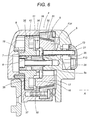
- Figures 5 and 6 also show how the reciprocal connecting parts 11 comprise a circular selector element 14, attached to the pin 7 coaxially and in such a way that it can rotate, forming the above-mentioned seat 8 for rotation of the mobile frame 3, and connected to the mobile half-body 6.
- This selector element 14 has a plurality of arced through-seats 15 which set the positions and the strokes which can be performed by the mobile frame 3, since the seats 15 are connected to a plurality of front radial projections 16 at preset distances on a contact flange 17 (see also Figure 11) which is connected to the fixed half-body 5, and through the centre of which the hinge pin 7 passes.
- Control means 13 act upon the selector element 14, parallel with the axis of rotation X. Said means can move the selector element 14 axially between a released position, in which the selector element 14 is distanced from the contact flange 17 (see arrow F13 in Figures 5 and 6) allowing operation of the cam means 12, and a rotating constrained position, in which the selector element 14 is moved towards the flange 17 and the projections 16 are engaged in arced seats 15 by the action of spring back means 18.
- Figure 11 also clearly shows, by way of example and without limiting the scope of the present invention, how there are three projections 16 (16a, 16b, 16c), evenly distributed along the flange 17, whilst there may be more arced seats 15 than projections 16, extending in an arc large enough to allow the mobile frame 3 opening and closing movements. At least one of these seats 15 forms an opening which can be connected, without a stroke, to that of the projections 16 which, as indicated below, allows stable positioning of the mobile frame 3 in the above-mentioned service position.
- cam means 12 may be operated using the control means 13, which are located on the fixed half-body 5, as described in detail below.
- the above-mentioned cam means 12 comprise a bearing 19 (see also Figures 7, 8 and 9) in a through-seat 20 made radially on the selector element 14 in such a way that it is positioned close to the hinge pin 7, by adjustable elastic means 21, and a pair of straight races 22a and 22b, opposite one another, made on the pin 7 connected to the fixed half-body 5, and designed so that, when the selector element 14 is in the released position, they allow partial protrusion of the bearing 19 (see arrow F19 in Figures 7 and 9), allowing this released position to be maintained at least for a rotation of the mobile frame 3 equivalent to the passage from the open position to the service position and vice versa (positions illustrated in Figures 7 and 9).
- the above-mentioned bearing 19 is held in position close to the pin 7 by a spring 21 whose compression can be adjusted using an adjustment grub screw 23 which is connected in such a way that it may be tightened or slackened in the seat 20, and may be adjusted from the outside by means of a through-opening 24 in the mobile half-body 6.
- the selector element 14 is attached to the mobile half-body 6 by circumferential toothing 35 on the selector element, which can engage with a matching plurality of seats 36 on the mobile half-body 6.
- the numeral 18 denotes a spring inserted between the mobile half-body 6 and the selector element 14, forming the spring back means, acting upon the selector element 14 in such a way as to hold the selector element 14 in the position in which it is attached to the flange 17.
- control means 13 comprise a pushbutton 25, which may be operated manually, located in a seat 26 on the outside of the fixed half-body 5 (see Figures 5 and 6) .
- the pushbutton 25 has an activation pin 27 which passes through the fixed half-body 5 and the contact flange 17 in such a way that it is opposite the selector element 14, thus, when the pushbutton 25 is pressed, allowing at least the position in which the selector element 14 is released from the flange 17.
- the pushbutton 25 also has a pair of tabs 28, projecting from the edge of the pushbutton, engaged in slots 29 in the fixed half-body 5 (partially illustrated in Figure 10) and designed to allow stable and sliding connection of the pushbutton 25 in its seat 26.
- a spring 30 (illustrated with a dashed line in Figure 5) may be inserted between the pushbutton 25 and the fixed half-body 5.
- the spring allows the pushbutton 25 to return to a home position with the pin 27 distanced from the selector element 14 after engagement of the bearing 19 in the relative race 22a or 22b.
- this has a portion with a conical cross-section, extending towards the fixed half-body 5, on which there is a matching braking element 31 made of a material with a high friction coefficient and forming the above-mentioned clutch-control means 9.
- the flange 17 and this braking element 31 are held together by a cylindrical cover 32 attached to the mobile half-body 6 and housing all of the reciprocal connecting parts 11.
- the flange 17 is attached to the fixed half-body 5 by a cross-shaped axial projection 5s (see Figure 10), which may be attached to the flange 17, which has a matching through-seat 17a.
- the hinge pin 7 is stably connected to the axial projection 5s.
- the flange 17 and the braking element 31 have adjustment means 33 consisting of at least one pair of screws 33a and 33b which can be adjusted from the outside, thanks to a pair of holes 50 in the pushbutton 25, which can be connected in seats 34 on the flange 17 in such a way that they may be tightened or slackened.
- each half-body 5 and 6 has an outer extension 37 designed to allow connection, using screw means 38, to the fixed frame 2 and the mobile frame 3 through an opening 39 in the front of the frames. In this way, the half-bodies 5 and 6 are joined on inner profiles of the frames 2 and 3.
- At least one of the half-bodies 5 and 6 of each hinge 4 present can be attached to the corresponding frame 2 and 3 by a connecting plate 40 (see Figure 5a), directly connected to the corresponding frame 2 and 3.
- This plate 40 has a projecting channel 41 designed to form a bilateral longitudinal guide and connecting extension for a seal 42 common to the fixed and mobile frames 2 and 3.
- the connecting plate 40 is preferably, but without limiting the scope of the present invention, connected to the fixed half-body 5 which can be attached to the fixed frame 2 (as illustrated in Figure 12).
- a clutch-controlled hinge structured in this way functions as described below.
- the user can normally open and close the door or window frame 1 using the handle M (see arrow F in Figure 3), since the hinges 4 operate in conjunction with the flange 17 in contact with the selector 14 which, thanks to the shape of the arced seats 15, allows the mobile frame 3 to turn in both directions, until the projections 16 reach the ends of the arced seats 15.
- the user brings the mobile frame to the open position (with angle ⁇ normally around 30° or 45°, depending on the type of door or window frame 1), then must press the pushbutton 25 on one or both hinges 4 (if both have the above-mentioned configuration), allowing the selector 14 to move along the axis X, with the consequent movement of the selector away from the flange 17 (see arrow F13 and the connecting part configuration illustrated in Figure 7).
- the user can turn the mobile frame 3 completely, since the selector 14 is free to turn without constraint from the projections 16, until it reaches the service position (i.e.: turning through an angle of 180°, as illustrated in Figures 4 and 9).
- the rotation of the selector 14 also sets the angular movement of the bearing 19 relative to the pin 7 and, therefore, to the race 22a or 22b. This lowers the bearing 19 (see arrow 19a), partly thanks to the profile of the race 22a or 22b, to the point at which the bearing 19 returns within the seat 20, with the consequent movement of the selector 14 towards the flange 17 and engagement of the projections 16 in the seats 15 as is schematically illustrated in Figure 9.
- the mobile frame 3 is locked in the service position and the user can clean the outside of the glass with the mobile frame stably positioned at an angle of 180° to the fixed frame.
- a hinge of this type therefore, fulfils the stated aims, thanks to an actuating system which is extremely practical and safe, but also allows the user to move the mobile frame to a stable service or cleaning position rapidly and without excessive force.
- connecting plate with the joint channel for the seal also allows more rapid hinge fitting on the door or window frame.
Landscapes
- Engineering & Computer Science (AREA)
- Mechanical Engineering (AREA)
- Structural Engineering (AREA)
- Window Of Vehicle (AREA)
- Closing And Opening Devices For Wings, And Checks For Wings (AREA)
- Hinge Accessories (AREA)
Applications Claiming Priority (2)
| Application Number | Priority Date | Filing Date | Title |
|---|---|---|---|
| ITBO200037 | 2000-01-31 | ||
| IT2000BO000037A IT1321202B1 (it) | 2000-01-31 | 2000-01-31 | Cerniera frizionabile per infissi basculanti . |
Publications (2)
| Publication Number | Publication Date |
|---|---|
| EP1122388A1 true EP1122388A1 (de) | 2001-08-08 |
| EP1122388B1 EP1122388B1 (de) | 2004-09-22 |
Family
ID=11438114
Family Applications (1)
| Application Number | Title | Priority Date | Filing Date |
|---|---|---|---|
| EP01830047A Expired - Lifetime EP1122388B1 (de) | 2000-01-31 | 2001-01-26 | Kupplungsgesteuertes Scharnier für schwenkbare Tür- und Fensterrahmen |
Country Status (4)
| Country | Link |
|---|---|
| EP (1) | EP1122388B1 (de) |
| AT (1) | ATE277261T1 (de) |
| DE (1) | DE60105667D1 (de) |
| IT (1) | IT1321202B1 (de) |
Cited By (1)
| Publication number | Priority date | Publication date | Assignee | Title |
|---|---|---|---|---|
| FR2921090A1 (fr) * | 2007-09-14 | 2009-03-20 | Tellier G Soc Par Actions Simp | Charniere pour fenetre |
Citations (1)
| Publication number | Priority date | Publication date | Assignee | Title |
|---|---|---|---|---|
| FR2393912A1 (fr) * | 1977-06-09 | 1979-01-05 | Ferco Int Usine Ferrures | Pivot pour fenetre basculante ou pivotante |
-
2000
- 2000-01-31 IT IT2000BO000037A patent/IT1321202B1/it active
-
2001
- 2001-01-26 DE DE60105667T patent/DE60105667D1/de not_active Expired - Lifetime
- 2001-01-26 AT AT01830047T patent/ATE277261T1/de not_active IP Right Cessation
- 2001-01-26 EP EP01830047A patent/EP1122388B1/de not_active Expired - Lifetime
Patent Citations (1)
| Publication number | Priority date | Publication date | Assignee | Title |
|---|---|---|---|---|
| FR2393912A1 (fr) * | 1977-06-09 | 1979-01-05 | Ferco Int Usine Ferrures | Pivot pour fenetre basculante ou pivotante |
Cited By (1)
| Publication number | Priority date | Publication date | Assignee | Title |
|---|---|---|---|---|
| FR2921090A1 (fr) * | 2007-09-14 | 2009-03-20 | Tellier G Soc Par Actions Simp | Charniere pour fenetre |
Also Published As
| Publication number | Publication date |
|---|---|
| IT1321202B1 (it) | 2003-12-31 |
| EP1122388B1 (de) | 2004-09-22 |
| ITBO20000037A1 (it) | 2001-07-31 |
| ATE277261T1 (de) | 2004-10-15 |
| DE60105667D1 (de) | 2004-10-28 |
Similar Documents
| Publication | Publication Date | Title |
|---|---|---|
| US8070194B2 (en) | Mechanism for installing a control turning handle of a door lock and its deinstalling tool | |
| EP3348750B1 (de) | Griff für tür oder fenster | |
| US3911621A (en) | Multi-purpose window | |
| EP3189201B1 (de) | Entlüftungsbediener | |
| US6606825B2 (en) | Window opening and closing assembly | |
| US11598136B2 (en) | Furniture hinge with damping adjustment | |
| MXPA04002676A (es) | Combinacion plegable de manija de manivela y fijador. | |
| EP1122388B1 (de) | Kupplungsgesteuertes Scharnier für schwenkbare Tür- und Fensterrahmen | |
| AU2018341396B2 (en) | A window fastener | |
| JP2929097B2 (ja) | 開き窓の開閉装置 | |
| KR101880996B1 (ko) | 전후 방향 흔들림이 없이 안정적으로 닫히는 양방향 여닫이문 | |
| GB2134593A (en) | Door closing devices | |
| JP7672325B2 (ja) | 建具 | |
| EP1748127A2 (de) | Griff für Tür oder Fensterrahmen | |
| EP3744935A1 (de) | Nockenanordnung | |
| WO1985003102A1 (en) | Door handle and latch assembly | |
| US4640051A (en) | Adjustment mechanism for tiltable glazed sashes | |
| CN210013600U (zh) | 锁定机构及门窗结构 | |
| KR102094605B1 (ko) | 방화문용 제어장치 | |
| KR102019597B1 (ko) | 방화문용 도어클로저의 제어장치 | |
| WO2018002805A2 (en) | Hinge for the rotatable movement of a door or of a similar closing element | |
| CA2603172C (en) | Door lock | |
| KR101661462B1 (ko) | 미닫이 문 잠금장치 | |
| JP2600454Y2 (ja) | 蝶番並びにその蝶番を用いた開閉体の取付構造 | |
| KR200202045Y1 (ko) | 여닫이 창문의 개폐장치 |
Legal Events
| Date | Code | Title | Description |
|---|---|---|---|
| PUAI | Public reference made under article 153(3) epc to a published international application that has entered the european phase |
Free format text: ORIGINAL CODE: 0009012 |
|
| AK | Designated contracting states |
Kind code of ref document: A1 Designated state(s): AT BE CH CY DE DK ES FI FR GB GR IE IT LI LU MC NL PT SE TR |
|
| AX | Request for extension of the european patent |
Free format text: AL;LT;LV;MK;RO;SI |
|
| 17P | Request for examination filed |
Effective date: 20011019 |
|
| AKX | Designation fees paid |
Free format text: AT BE CH CY DE DK ES FI FR GB GR IE IT LI LU MC NL PT SE TR |
|
| 17Q | First examination report despatched |
Effective date: 20030626 |
|
| GRAP | Despatch of communication of intention to grant a patent |
Free format text: ORIGINAL CODE: EPIDOSNIGR1 |
|
| GRAS | Grant fee paid |
Free format text: ORIGINAL CODE: EPIDOSNIGR3 |
|
| GRAA | (expected) grant |
Free format text: ORIGINAL CODE: 0009210 |
|
| AK | Designated contracting states |
Kind code of ref document: B1 Designated state(s): AT BE CH CY DE DK ES FI FR GB GR IE IT LI LU MC NL PT SE TR |
|
| PG25 | Lapsed in a contracting state [announced via postgrant information from national office to epo] |
Ref country code: BE Free format text: LAPSE BECAUSE OF FAILURE TO SUBMIT A TRANSLATION OF THE DESCRIPTION OR TO PAY THE FEE WITHIN THE PRESCRIBED TIME-LIMIT Effective date: 20040922 Ref country code: CH Free format text: LAPSE BECAUSE OF FAILURE TO SUBMIT A TRANSLATION OF THE DESCRIPTION OR TO PAY THE FEE WITHIN THE PRESCRIBED TIME-LIMIT Effective date: 20040922 Ref country code: LI Free format text: LAPSE BECAUSE OF FAILURE TO SUBMIT A TRANSLATION OF THE DESCRIPTION OR TO PAY THE FEE WITHIN THE PRESCRIBED TIME-LIMIT Effective date: 20040922 Ref country code: NL Free format text: LAPSE BECAUSE OF FAILURE TO SUBMIT A TRANSLATION OF THE DESCRIPTION OR TO PAY THE FEE WITHIN THE PRESCRIBED TIME-LIMIT Effective date: 20040922 Ref country code: FI Free format text: LAPSE BECAUSE OF FAILURE TO SUBMIT A TRANSLATION OF THE DESCRIPTION OR TO PAY THE FEE WITHIN THE PRESCRIBED TIME-LIMIT Effective date: 20040922 Ref country code: TR Free format text: LAPSE BECAUSE OF FAILURE TO SUBMIT A TRANSLATION OF THE DESCRIPTION OR TO PAY THE FEE WITHIN THE PRESCRIBED TIME-LIMIT Effective date: 20040922 Ref country code: AT Free format text: LAPSE BECAUSE OF FAILURE TO SUBMIT A TRANSLATION OF THE DESCRIPTION OR TO PAY THE FEE WITHIN THE PRESCRIBED TIME-LIMIT Effective date: 20040922 |
|
| REG | Reference to a national code |
Ref country code: GB Ref legal event code: FG4D |
|
| REG | Reference to a national code |
Ref country code: CH Ref legal event code: EP |
|
| REG | Reference to a national code |
Ref country code: IE Ref legal event code: FG4D |
|
| REF | Corresponds to: |
Ref document number: 60105667 Country of ref document: DE Date of ref document: 20041028 Kind code of ref document: P |
|
| PG25 | Lapsed in a contracting state [announced via postgrant information from national office to epo] |
Ref country code: GR Free format text: LAPSE BECAUSE OF FAILURE TO SUBMIT A TRANSLATION OF THE DESCRIPTION OR TO PAY THE FEE WITHIN THE PRESCRIBED TIME-LIMIT Effective date: 20041222 Ref country code: SE Free format text: LAPSE BECAUSE OF FAILURE TO SUBMIT A TRANSLATION OF THE DESCRIPTION OR TO PAY THE FEE WITHIN THE PRESCRIBED TIME-LIMIT Effective date: 20041222 Ref country code: DK Free format text: LAPSE BECAUSE OF FAILURE TO SUBMIT A TRANSLATION OF THE DESCRIPTION OR TO PAY THE FEE WITHIN THE PRESCRIBED TIME-LIMIT Effective date: 20041222 |
|
| PG25 | Lapsed in a contracting state [announced via postgrant information from national office to epo] |
Ref country code: DE Free format text: LAPSE BECAUSE OF FAILURE TO SUBMIT A TRANSLATION OF THE DESCRIPTION OR TO PAY THE FEE WITHIN THE PRESCRIBED TIME-LIMIT Effective date: 20041223 |
|
| PG25 | Lapsed in a contracting state [announced via postgrant information from national office to epo] |
Ref country code: ES Free format text: LAPSE BECAUSE OF FAILURE TO SUBMIT A TRANSLATION OF THE DESCRIPTION OR TO PAY THE FEE WITHIN THE PRESCRIBED TIME-LIMIT Effective date: 20050102 |
|
| PG25 | Lapsed in a contracting state [announced via postgrant information from national office to epo] |
Ref country code: IE Free format text: LAPSE BECAUSE OF NON-PAYMENT OF DUE FEES Effective date: 20050126 Ref country code: CY Free format text: LAPSE BECAUSE OF FAILURE TO SUBMIT A TRANSLATION OF THE DESCRIPTION OR TO PAY THE FEE WITHIN THE PRESCRIBED TIME-LIMIT Effective date: 20050126 Ref country code: LU Free format text: LAPSE BECAUSE OF NON-PAYMENT OF DUE FEES Effective date: 20050126 Ref country code: GB Free format text: LAPSE BECAUSE OF NON-PAYMENT OF DUE FEES Effective date: 20050126 |
|
| PG25 | Lapsed in a contracting state [announced via postgrant information from national office to epo] |
Ref country code: MC Free format text: LAPSE BECAUSE OF NON-PAYMENT OF DUE FEES Effective date: 20050131 |
|
| REG | Reference to a national code |
Ref country code: CH Ref legal event code: PL |
|
| NLV1 | Nl: lapsed or annulled due to failure to fulfill the requirements of art. 29p and 29m of the patents act | ||
| PLBE | No opposition filed within time limit |
Free format text: ORIGINAL CODE: 0009261 |
|
| STAA | Information on the status of an ep patent application or granted ep patent |
Free format text: STATUS: NO OPPOSITION FILED WITHIN TIME LIMIT |
|
| ET | Fr: translation filed | ||
| 26N | No opposition filed |
Effective date: 20050623 |
|
| GBPC | Gb: european patent ceased through non-payment of renewal fee |
Effective date: 20050126 |
|
| REG | Reference to a national code |
Ref country code: IE Ref legal event code: MM4A |
|
| PG25 | Lapsed in a contracting state [announced via postgrant information from national office to epo] |
Ref country code: PT Free format text: LAPSE BECAUSE OF NON-PAYMENT OF DUE FEES Effective date: 20050222 |
|
| PGFP | Annual fee paid to national office [announced via postgrant information from national office to epo] |
Ref country code: FR Payment date: 20080108 Year of fee payment: 8 |
|
| REG | Reference to a national code |
Ref country code: FR Ref legal event code: ST Effective date: 20091030 |
|
| PG25 | Lapsed in a contracting state [announced via postgrant information from national office to epo] |
Ref country code: FR Free format text: LAPSE BECAUSE OF NON-PAYMENT OF DUE FEES Effective date: 20090202 |
|
| PGFP | Annual fee paid to national office [announced via postgrant information from national office to epo] |
Ref country code: IT Payment date: 20110128 Year of fee payment: 11 |
|
| PG25 | Lapsed in a contracting state [announced via postgrant information from national office to epo] |
Ref country code: IT Free format text: LAPSE BECAUSE OF NON-PAYMENT OF DUE FEES Effective date: 20120126 |