EP1122631A2 - Elektronisches Gerät und Fernsehspielvorrichtung mit Wärmestrahlungsstruktur - Google Patents
Elektronisches Gerät und Fernsehspielvorrichtung mit Wärmestrahlungsstruktur Download PDFInfo
- Publication number
- EP1122631A2 EP1122631A2 EP01300726A EP01300726A EP1122631A2 EP 1122631 A2 EP1122631 A2 EP 1122631A2 EP 01300726 A EP01300726 A EP 01300726A EP 01300726 A EP01300726 A EP 01300726A EP 1122631 A2 EP1122631 A2 EP 1122631A2
- Authority
- EP
- European Patent Office
- Prior art keywords
- heat
- air
- electronic equipment
- radiating
- air intake
- Prior art date
- Legal status (The legal status is an assumption and is not a legal conclusion. Google has not performed a legal analysis and makes no representation as to the accuracy of the status listed.)
- Ceased
Links
Images

Classifications
-
- H—ELECTRICITY
- H05—ELECTRIC TECHNIQUES NOT OTHERWISE PROVIDED FOR
- H05K—PRINTED CIRCUITS; CASINGS OR CONSTRUCTIONAL DETAILS OF ELECTRIC APPARATUS; MANUFACTURE OF ASSEMBLAGES OF ELECTRICAL COMPONENTS
- H05K7/00—Constructional details common to different types of electric apparatus
- H05K7/20—Modifications to facilitate cooling, ventilating, or heating
-
- G—PHYSICS
- G06—COMPUTING OR CALCULATING; COUNTING
- G06F—ELECTRIC DIGITAL DATA PROCESSING
- G06F1/00—Details not covered by groups G06F3/00 - G06F13/00 and G06F21/00
- G06F1/16—Constructional details or arrangements
- G06F1/20—Cooling means
-
- A—HUMAN NECESSITIES
- A63—SPORTS; GAMES; AMUSEMENTS
- A63F—CARD, BOARD, OR ROULETTE GAMES; INDOOR GAMES USING SMALL MOVING PLAYING BODIES; VIDEO GAMES; GAMES NOT OTHERWISE PROVIDED FOR
- A63F2300/00—Features of games using an electronically generated display having two or more dimensions, e.g. on a television screen, showing representations related to the game
- A63F2300/20—Features of games using an electronically generated display having two or more dimensions, e.g. on a television screen, showing representations related to the game characterised by details of the game platform
-
- A—HUMAN NECESSITIES
- A63—SPORTS; GAMES; AMUSEMENTS
- A63F—CARD, BOARD, OR ROULETTE GAMES; INDOOR GAMES USING SMALL MOVING PLAYING BODIES; VIDEO GAMES; GAMES NOT OTHERWISE PROVIDED FOR
- A63F9/00—Games not otherwise provided for
- A63F9/24—Games using electronic circuits not otherwise provided for
Definitions
- This invention relates to an electronic equipment and television game machine having a heat-radiating structure. More particularly, the invention relates to an electronic equipment and television game machine having a heat-radiating structure which is applicable for the electronic equipment, such as home-use video game machines and DVD players, incorporating semiconductor devices (CPU, etc.) and adapted to release the heat generated upon operation of digital processing, such as image processing, by the semiconductor devices and prevent the semiconductor devices from being thermally broken down.
- the electronic equipment such as home-use video game machines and DVD players, incorporating semiconductor devices (CPU, etc.) and adapted to release the heat generated upon operation of digital processing, such as image processing, by the semiconductor devices and prevent the semiconductor devices from being thermally broken down.
- the electronic equipment such as personal computers, home-use video game machines (TV game machines) and DVD players, incorporate therein a printed board mounting semiconductor devices, such as a central processor unit (CPU) for high-speed processing and image processor unit.
- a printed board mounting semiconductor devices such as a central processor unit (CPU) for high-speed processing and image processor unit.
- CPU central processor unit
- Prior Art 1 has a heat-radiating plate directly connected to semiconductor devices, such as a CPU, to allow for spontaneous heat radiation through the heat-radiating plate (spontaneous heat-radiating scheme).
- Prior Art 2 discloses a technology that a small-sized fan is installed in a position above a CPU and the like to provide forcible heat radiation (forcible heat-radiating scheme in Figure 8 to Figure 10) and further a scheme that a heat-radiating plate is connected to the CPU and the like and a heat pipe is attached to the heat-radiating plate so that the heat-radiating plate and heat pipe is extended to a position of the small fan to perform forcible cooling (forcible cooling scheme in Figure 1 to Figure 7).
- the conventional notebook personal computer has arrangement, in different areas in plan, of an optical information reading unit for reading from optical information recording mediums and a printed board mounting semiconductor devices such as CPU.
- the semiconductor devices can be prevented from being thermally broken down at low cost.
- a sufficient heat-radiating effect is unavailable for those having a high operating frequency of the CPU, etc. for high-speed processing or highly integrated semiconductor devices with great heat generation.
- the spontaneous heat-radiating scheme generally there is a limitation in volume of an electronic-equipment housing to nearly 10 W/1 litter. It is said that, where this is exceeded, there is a need to employ a forcible heat-radiating scheme or forcible cooling scheme.
- the electronic equipment is a notebook personal computer, it is usually used on the desk or knee and hence free from problems even if its size is large in plan.
- the electronic equipment is a home-use television game machine, it is used in a place nearby a home-use television receiver and, in many cases, on the floor. In such a case, the form in plan if large is obstructive.
- the various interior parts are probably damaged, besides the damage to the housing. If the damage was to a printed board mounting an expensive optical information reading unit, CPU, etc., repair cost would be expensive possibly resulting in a problem of increased burden upon the user.
- Another object of the present invention is to provide an electronic equipment and television game machine having a heat-radiating effect high in heat-radiating effect, despite cheap in structure, by properly selecting the structure of a heat-radiating member and a positional relationship between an air intake, an air exit and a heat-radiating fan for forcible air discharge.
- a still another object of the present invention is to provide an electronic equipment and television game machine having a heat-radiating structure which is inexpensive but excellent in heat-radiating effect without the need of using an expensive heat pipe or a small-sized fan using aluminum die casting.
- a yet another object of the present invention is to provide an electronic equipment and television game machine having a heat-radiating structure which is small in plan, not obstructive upon use but capable of reducing the possibility of being trodden by mistake, wherein, even if trodden by mistake, the interior parts are less damaged.
- An electronic equipment having a hear-radiating structure (a first invention of claim 1) comprises at least one semiconductor device, a printed board, a housing, a radiating member and a radiating fan.
- the semiconductor device by its operation, effects a desired operation of the electronic equipment and has heat generation during the operation, which includes for example a central processing unit (CPU), an image processing unit, a sound-source processing unit, a semiconductor memory and so on. At least one semiconductor device is mounted on the printed board.
- the housing has a space for accommodating therein the printed board, and is structured having an air exit formed in a side surface and an air intake formed in a position distant from the air exit to have an air flow passage to allow air on a line connecting between the air exit and the air intake (any of a straight line or a curved line).
- the heat-radiating member is arranged on the air flow passage within the housing, structured in electric insulation from the semiconductor device and to transfer the heat generated from the semiconductor device, and has a plurality of grooves formed along the air flow passage.
- the heat-radiating fan is provided between at least one of the air intake and the air exit and one end of the heat-radiating member closer thereto.
- the heat generated from the semiconductor device is conveyed to the heat-radiating member and then dissipated through a plurality of heat-radiating fins on the heat-radiating member.
- the heat-radiating fan is rotated to intake air through the air intake and/or forcibly discharge (or ventilate) it through the air exit, cool air (ambient air) outside the housing is taken through the air intake.
- the cool air is caused to flow along the air flow passage including the grooves of the heat-radiating member whereby it is forcibly discharged together with the heat dissipated from the heat-radiating member to the outside of the housing through the air exit. This cools the heat-radiating member and the semiconductor device.
- a unique effect is provided that a preferred heat-radiating effect is obtainable in such an extent as to prevent the semiconductor device from being thermally broken down, providing a heat-radiating structure excellent in cost performance.
- An electronic equipment is an electronic equipment to be used connected to a display device and removably attached with an optical information recording medium optically recording data for image display, and comprises an optical information reading unit, at least one semiconductor element, a printed board, a housing, a heat-radiating member and a heat-radiating fan.
- the semiconductor device by its operation, effects a desired operation of the electronic equipment and has heat generation during the operation, which includes for example a central processing unit (CPU), an image processing unit, a sound-source processing unit, a semiconductor memory and so on.
- a semiconductor device is mounted on the printed board.
- the housing has attaching portion formed in a top surface thereof to removably attach an optical information recording medium and a space for stacking and accommodating, at least, the optical information reading unit and the printed board in a height direction, to accommodate the optical information reading unit in a position related to the attaching portion and the printed board in a position below the optical information reading unit with a predetermined spacing and form an air exit in a side surface related to an accommodating position of the printed board in the height direction and an air intake in a position distant from the air exit to have an air flow passage to allow air on a line connecting between the air exit and the air intake.
- the heat-radiating member is arranged on the air flow passage within the housing, structured in electric insulation from the semiconductor device and to transfer the heat generated from the semiconductor device, and has a plurality of grooves formed along the air flow passage.
- the heat-radiating fan is provided between at least one of the air intake and the air exit and one end of the heat-radiating member closer thereto.
- an optical information recording medium is attached on the optical information reading unit.
- the optical information reading unit reads out data for image display recorded on the optical information recording medium.
- the semiconductor device processes the data for image display read by the optical information reading unit thereby generating image data for display and supplying it to the display device, during operation of which heat is generated.
- the heat generated from the semiconductor device is conveyed to the heat-radiating member and then dissipated through a plurality of heat-radiating fins on the heat-radiating member.
- the heat-radiating fan is rotated to intake air through the air intake and/or forcibly discharge (or ventilate) it through the air exit, cool air (ambient air) outside the housing is taken through the air intake.
- the cool air is caused to flow along the air flow passage including the grooves of the heat-radiating member whereby it is forcibly discharged together with the heat dissipated from the heat-radiating member to the outside of the housing through the air exit. This cools the heat-radiating member and the semiconductor device.
- the printed board and the heat-radiating member are covered by a metal case in a box form.
- the housing can be reduced in plan shape.
- the equipment is less obstructive and reduces the possibility of treading on by the user.
- treading on by mistake a unique effect is provided that various interior parts be less damaged.
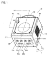
- Figure 1 is a perspective view, as viewed from an upper front, of a television game machine as one example of an electronic equipment having a heat-radiating structure according to one embodiment of the invention.
- Figure 2 is a perspective view of the television game machine as viewed from the front and right side.
- Figure 3 is a perspective view of the television game machine as viewed from the rear and back.
- the television game machine (or television game machine main body) 10 includes a housing 11 generally in a cubic form, as shown in Figure 1 to Figure 3.
- the housing 11 is structured by an upper housing 11a and a lower housing 11b.
- the upper housing 11a in its front surface is formed with an aperture 111.
- a controller-connection panel 12 hereinafter referred to, is attached.
- An air intake 112 is formed in one side surface (right side surface as viewed from the front) of the upper housing 11a.
- An air exit 113 is formed in the other side surface (left side surface as viewed from the front) opposite to the air intake 112.
- These air intake 112 and air exit 113 may be structured by forming a plurality of penetration holes as shown in the figure, or otherwise by arranging a mesh-form filter in a single, large penetration hole.
- a lid member 13 is attached for open and close on a top surface of the upper housing 11a (planer surface as viewed in Figure 1 and Figure 2). The lid member 13 is opened and closed, for example, when an optical information recording medium such as a CD-ROM or DVD is inserted.
- a power switch 14 is provided on the top surface of the upper housing 11a.
- a grip 15 for carrying the television game machine 10 and an aperture 114 are formed in the back surface of the housing 11.
- the lower housing 11b in its bottom surface is formed with a recess (or aperture recess) to receive therein a memory unit 31 and a recess (or aperture recess) 116 to receive a communication modem unit 32, as will be concretely shown in Figure 4 hereinafter referred to.
- a memory unit 31 used for the purpose of extension for RAM 44 as will be hereinafter described.
- Received in the recess 116A is a modem unit 32 for extending communication functions.
- the recess 115 and memory unit 31, the recess 117 and communication modem unit 32 are respectively formed with lock mechanisms (not shown) comprising engaging pawls and engaging recesses, in order to provide a structure for engagement and disengagement.
- the controller-connection panel 12 has connectors 22a - 22d to removably connect controllers (or game controllers; not shown) of the television game machine 10, and connectors 23a, 23b to removably connect memory cartridges (not shown) for storing backup data.
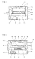
- Figure 4 is a sectional view taken along line IV-IV in Figure 1
- Figure 5 is a sectional view taken along line V-V in Figure 1.
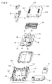
- Figure 6 and Figure 7 are exploded perspective views concretely showing an interior structure of the television game machine 10. Next, with reference to Figure 4 and Figure 7, explanations will be made in detail on a heat-radiating structure of the television game machine 10.
- the lower housing 11b is generally square in plan, and has side walls 117 in a manner encompassing a planer portion thereof.
- a plurality of spacers 118 are formed in the lower housing 11b and surrounded by the side walls 117, to hold a printed board 41 and a hereinafter-described optical information reading unit 60 in a predetermined relationship of position.
- Connector-insertion holes are formed in the recess 115 and recess 116 formed in a bottom of the lower housing 11b.
- the printed board 41 (see Figure 4 to Figure 6) is accommodated in the housing 11.
- the printed board 41 is formed with a predetermined circuit pattern.
- semiconductor devices or semiconductor parts 42 - 44 are mounted along an air flow passage, hereinafter described.
- the semiconductor devices include, for example, a central processing unit (CPU) 42 to execute game programs, an image processing unit (or image processor IC) 43 and writable memory (RAM) 44.
- This RAM 44 is used as a graphic memory to store image data to be image-processed in a bit-map form and/or a working memory to temporarily store a variety of data under processing.
- These semiconductor devices 42 - 44 are arranged and mounted in a sideway direction (i.e.
- the image processing unit 43 is the greatest in heat generation and the CPU 42 is the second greatest.
- the printed board 41 has connectors 33, 34 fitted in positions on the bottom surface corresponding to the mount positions of a memory unit 31 and a communication modem unit 32 to be electrically connected to a predetermined circuit pattern on the printed board 41. These connectors 33, 34 are exposed through the connector-insertion holes in the recess 115 and recess 116. Furthermore, the printed board 41 has connectors 35, 36 attached in a front end thereof, for electrical connection to the connectors 21a - 21d and 22a, 22b of the controller-connection panel 20. The printed board 41 has connectors 37, 38 attached in a rear end thereof, for connection to a power supply and AV cable.
- the semiconductor device 42 - 44 has electrically-insulating and thermally-conductive sheet (not shown) adhered at a top surface of a package thereof.
- a heat-radiating member 45 is bonded along an direction of air flow, hereinafter described.
- the heat-radiating member 45 is structured, as shown for example in Figure 5, in a comb form in section having a plurality of heat-radiating fins and grooves formed integral on a plate portion thereof.
- the air flow passage connecting between the air intake 112 and the air exit 113 is in a linear form, i.e.
- the heat-radiating member 45 in plan is formed in an oblong or square rectangular form.
- the number of the heat-radiating fins and/or the number of grooves between two heat-radiating fins is determined based on a quantity of heat generation by the semiconductor devices 42 - 44 as calculated by a predetermined calculation formula.
- the heat-radiating member 45, where rectangular in plan, is formed by hot extrusion of aluminum.
- the heat-radiating member 45 may be formed by aluminum die casting or cutting out (an aluminum plate having a large wall thickness is cut at a constant interval to thereby form a plurality of grooves and heat-radiating fins).
- a metal case 51 is accommodated in the housing 11.
- the metal case 51 is used to confine heat, in a state of covering the printed board 41 mounting the semiconductor devices 42- 44 and the heat-radiating member 45, and at the same time for preventing electromagnetic waves from unwantedly radiating and leaking to an outside.
- the metal case 51 comprises an upper case 51 and a lower case 51b.
- the space defined by the upper case 51a and the lower case 51b is selected to accommodate the printed board 41 mounting various electronic parts.
- penetration holes 111 and second penetration holes 512 are first formed in positions (on the side of the right air intake 112 as viewed from the front and on the side of the right air exit 113 as viewed from the front) corresponding to the side surface (or a plurality of grooves) in a direction along the heat-radiating fins (in the left and right as viewed from the front) of the heat-radiating member 45.
- the first penetration holes 511 and the second penetration holes 512 are selected in position such that a predetermined number of holes are opened in a position corresponding to each groove of the heat-radiating member 45 with respect to a direction of the groove but no holes are opened in an area opposed to heat-radiating fin.
- a plurality of penetration holes 513 are formed in the top surface of the upper case 51a in a position close to the air exit 113, in order to increase the area of the air exit.
- a heat-radiating fan 52 is provided between the air exit 113 and the heat-radiating member 45.
- the heat-radiating fan 52 uses a vertical-type fan structured to rotate a fan by a small-sized motor.
- a duct 53 is formed between heat-radiating fan 52 and the upper case 51a forming the penetration holes 512, 513, in order to discharge air with efficiency.
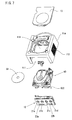
- a circular aperture 119 is formed in the top surface of upper housing 11a.
- a lid 13 is attached for open and close to cover the aperture 119.
- An optical information reading unit 60 is accommodated below the aperture 119.
- the optical information reading unit 60 is to read out information optically recorded on the optical information recording medium 61, such as a CD-ROM or DVD, and includes a support mechanism to rotatably support the optical information recording medium 61, a pickup part 63, a rotary mechanism 64 and a positioning mechanism 65 for the pickup part 63.
- the support mechanism 62 has side-wall portion 621 formed in the lower position thereof to extend along a planar peripheral edge.
- the side-wall portion 621 is formed such that, even if the heat generated from the semiconductor devices 42 - 44 of the printed board 41 and dissipated through the heat-radiating member 45 partly leeks from the metal case 51, it can be reduced from being conveyed to the pickup part 63 in the optical information reading unit 60. This is because the pickup part 63 is thermally the least weak part among the electronic parts used in the electronic equipment 10.
- the pickup part 63 includes a light emitting element such as a light-emitting diode for semiconductor laser, a light-receiving element for receiving reflection light that the light emitted from the light-emitting element reflect upon the optical information recording medium 61 and then returns, a positioning mechanism for changing the position of the light-emitting element and light-receiving element.
- a light emitting element such as a light-emitting diode for semiconductor laser
- a light-receiving element for receiving reflection light that the light emitted from the light-emitting element reflect upon the optical information recording medium 61 and then returns
- a positioning mechanism for changing the position of the light-emitting element and light-receiving element.
- a control circuit board 65 is accommodated in a position below the optical information reading unit 60 in the housing, in order to drive and control the optical information reading unit 60.
- the control circuit board 65 is covered by a metal case 66 to reduce or prevent electromagnetic wave noise or unwanted radiation.
- penetration holes for air intake and discharge are formed in a side surface of the metal case 66. It is noted that the heat generation by the circuit parts mounted on the control circuit board 65 is by per less as compared to that of the semiconductor devices 42 - 44 mounted on the printed board 41. Accordingly, the number of penetration holes (or total area of the penetration holes) formed in the metal case 65 is satisfactorily by far less as compared to the number of the penetration holes 511 - 513 (total area of the penetration holes) in the metal case 51.
- the television game machine 10 is assembled by the following process. That is, the lower housing 11b is placed on a working table.
- the lower case 51b is received and positioned in a predetermined position inside the lower housing 11b. Stacked thereon the printed board 41 mounting semiconductor devices 42 - 44, a heat-radiating member 45, connectors 33, 34 and other required electronic parts. Covered thereon the upper case 51. In this case, positioning is made such that the grooves and heat-radiating fins of the heat-radiating member 45 are positioned on the air flow passage extending from the air intake 112 to the air exit 113.
- a heat-radiating fan 52 is arranged in a position close to the penetration holes 512, 513.
- the control circuit board 65 covered with a metal case 66 is placed on the metal case 51. Stacked thereon is the optical information reading unit 60. Further, the support pillars 622 formed in a bottom surface of the optical information reading unit 60 are fitted to at least two spacers 118 formed on the lower housing 11b.
- the operation panel 12 is prepared in a state previously attached with connectors 21a - 21d for connecting the controllers (not shown) of the television game machine, and the connectors 22a, 22b for connecting a backup memory (not shown).
- the operation panel 12 is engaged in an upper front part of the lower housing 51b.
- a power switch 14 is attached to the metal case 51a.
- the upper housing 11a is covered over the optical information reading unit 60.
- the upper housing 11a and the lower housing 11b are screwed together by tightening screws (not shown) from the backside of the lower housing 11b. Thereafter, the lid member 13 for open and close is attached to the top surface of the upper housing 11a.
- the lower case 51a of the metal case 51, the printed board 41, the upper case 51b, the control circuit board 65, the metal case 66 and the optical information reading unit 60 are stacked and accommodated in the order from the below within the housing 11.
- the heat-radiating member is provided on the air flow passage connecting between the air intake and the air exit that are formed in the side surfaces of the housing 11.
- the dissipation heat from the heat-radiating fins of the heat-radiating member can be forcibly released by the heat-radiating fan arranged at the end of the air flow passage. Accordingly, with comparatively inexpensive structure, the heat-radiating member and the semiconductor devices can be cooled with efficiency thus providing preferred heat-radiating effects in such a degree as to prevent the semiconductor devices from thermally broken down.
- a heat-radiating structure excellent in cost performance is provided.
- the printed board and the heat-radiating member is covered by a box-formed metal case.
- This allows air to flow along the air flow passage including the grooves of the heat-radiating member and exit with efficiency while heat is confined within the metal case. This makes it possible to reduce the heat from being transferred to an outside of the metal case, thus suppressing adverse thermal effect upon other parts.
- the lower case 51a of the metal case 51, the printed board 41, the upper case 51b, the control circuit board 65, the metal case 66 and the optical information reading unit 60 are stacked in the order from the below within the case 11.
- the housing 51 is made generally in a cubic form by reducing the plan shape thereof but extending in a height (thickness) direction.
- the television game machine 10 even if put on the floor and used there, comparatively less space is occupied and hence not obstructive, reducing the possibility of being trodden by a user.
- the user can readily recognize treading something before moving the body weight to the treading foot. It is possible to prevent against treading on by the total body weight.
- the generally cubic form of the housing 11 increases the strength of the housing 11 itself higher than that of a flat-formed housing structure alike the notebook personal computer, further reducing the possibility of damage or breakage due to mistakenly treading on by the user.
- the memory unit 31 and/or the communication modem unit 32 are marketed separate from the television game machine 10.
- the user can purchase same as required and attached it to the lower housing 11b of the television game machine into electrical connection to the printed board 41, using extension functions.
- a hard disk may be connected to the connector 34.
- the inventors confirmed by experiments that the temperature inside the housing 11 was below a permissible upper temperature for the semiconductor devices 42 - 44 in a region close to or around the semiconductor devices 42 - 44.
- the heat-radiating structure of this invention is usable, as applications of the electronic equipment in this invention, for equipment such as personal computers, CD players and DVD players.
- the connectors and operation switches, etc. in used will be different depending upon the kind/application of electronic equipment to which this invention is applied.
- the electronic equipment is a DVD player
- provisions will be made with various switches for operating the DVD player, indicators for indicating operating state and so on.
- an air intake 62 and the air exit 113 are formed in the adjacent side surfaces (or in orthogonal side surfaces; for example, the air intake 112 is in a back surface and the air exit 113 in a left side surface, an air flow passage connecting between the air intake 112 and the air exit 113 is in an arcuate form (or in an L-letter form having a small arc in the corner), and a heat-radiating member 45 in plan is in an arcuate form (or an L-letter form) extending along the air flow passage.
- the air intake 112 and air exit 113 may be formed in the front and back surfaces of the housing 11.
- the arrangement position of semiconductor devices 42 - 44 on the printed board 41 and the direction of the grooves in a heat-radiating member 45 will be modified matched to the positions of the air intake 112 and air exit 113.
- the heat-radiating fan 52 is used as an air-discharging fan.
- it may be used as a fan for air intake by arranging it between the air intake 112 and the heat-radiating member 45.
- the heat-radiating fan 52 may be provided both on the air intake 112 and on the air exit 113.
Landscapes
- Engineering & Computer Science (AREA)
- Theoretical Computer Science (AREA)
- Physics & Mathematics (AREA)
- Human Computer Interaction (AREA)
- General Engineering & Computer Science (AREA)
- General Physics & Mathematics (AREA)
- Thermal Sciences (AREA)
- Microelectronics & Electronic Packaging (AREA)
- Cooling Or The Like Of Electrical Apparatus (AREA)
Applications Claiming Priority (2)
| Application Number | Priority Date | Filing Date | Title |
|---|---|---|---|
| JP2000020261 | 2000-01-28 | ||
| JP2000020261A JP2001210981A (ja) | 2000-01-28 | 2000-01-28 | 放熱構造を有する電子機器および放熱構造を有するテレビゲーム機 |
Publications (2)
| Publication Number | Publication Date |
|---|---|
| EP1122631A2 true EP1122631A2 (de) | 2001-08-08 |
| EP1122631A3 EP1122631A3 (de) | 2003-02-05 |
Family
ID=18546853
Family Applications (1)
| Application Number | Title | Priority Date | Filing Date |
|---|---|---|---|
| EP01300726A Ceased EP1122631A3 (de) | 2000-01-28 | 2001-01-26 | Elektronisches Gerät und Fernsehspielvorrichtung mit Wärmestrahlungsstruktur |
Country Status (11)
| Country | Link |
|---|---|
| US (1) | US6565444B2 (de) |
| EP (1) | EP1122631A3 (de) |
| JP (1) | JP2001210981A (de) |
| KR (1) | KR100747316B1 (de) |
| CN (1) | CN1205525C (de) |
| AU (1) | AU779571B2 (de) |
| BR (1) | BR0102363A (de) |
| CA (1) | CA2332200C (de) |
| HK (1) | HK1039989B (de) |
| MX (1) | MXPA01000977A (de) |
| TW (1) | TW566220U (de) |
Cited By (1)
| Publication number | Priority date | Publication date | Assignee | Title |
|---|---|---|---|---|
| EP1591871A1 (de) * | 2004-04-29 | 2005-11-02 | Shuttle Inc. | Wärmesenkestruktur für Computer |
Families Citing this family (95)
| Publication number | Priority date | Publication date | Assignee | Title |
|---|---|---|---|---|
| US7749089B1 (en) | 1999-02-26 | 2010-07-06 | Creative Kingdoms, Llc | Multi-media interactive play system |
| US7878905B2 (en) | 2000-02-22 | 2011-02-01 | Creative Kingdoms, Llc | Multi-layered interactive play experience |
| US6761637B2 (en) | 2000-02-22 | 2004-07-13 | Creative Kingdoms, Llc | Method of game play using RFID tracking device |
| US7445550B2 (en) | 2000-02-22 | 2008-11-04 | Creative Kingdoms, Llc | Magical wand and interactive play experience |
| US7066781B2 (en) | 2000-10-20 | 2006-06-27 | Denise Chapman Weston | Children's toy with wireless tag/transponder |
| US7474536B2 (en) * | 2000-10-27 | 2009-01-06 | Ridley Ray B | Audio sound quality enhancement apparatus and method |
| US6966837B1 (en) | 2001-05-10 | 2005-11-22 | Best Robert M | Linked portable and video game systems |
| KR100773502B1 (ko) * | 2001-10-05 | 2007-11-06 | 엘지전자 주식회사 | 휴대용 전자기기 |
| US20070066396A1 (en) | 2002-04-05 | 2007-03-22 | Denise Chapman Weston | Retail methods for providing an interactive product to a consumer |
| US6967566B2 (en) | 2002-04-05 | 2005-11-22 | Creative Kingdoms, Llc | Live-action interactive adventure game |
| US9446319B2 (en) | 2003-03-25 | 2016-09-20 | Mq Gaming, Llc | Interactive gaming toy |
| JP3108586U (ja) * | 2004-11-04 | 2005-04-28 | 船井電機株式会社 | 映像再生機能付きテレビジョンおよび電子機器 |
| USD556835S1 (en) * | 2005-05-11 | 2007-12-04 | Nintendo Co., Ltd. | Electronic game machine |
| JP4125318B2 (ja) * | 2005-02-24 | 2008-07-30 | アルゼ株式会社 | 遊技機 |
| US7942745B2 (en) | 2005-08-22 | 2011-05-17 | Nintendo Co., Ltd. | Game operating device |
| JP4805633B2 (ja) | 2005-08-22 | 2011-11-02 | 任天堂株式会社 | ゲーム用操作装置 |
| US7927216B2 (en) | 2005-09-15 | 2011-04-19 | Nintendo Co., Ltd. | Video game system with wireless modular handheld controller |
| US8313379B2 (en) | 2005-08-22 | 2012-11-20 | Nintendo Co., Ltd. | Video game system with wireless modular handheld controller |
| JP4262726B2 (ja) | 2005-08-24 | 2009-05-13 | 任天堂株式会社 | ゲームコントローラおよびゲームシステム |
| US8308563B2 (en) | 2005-08-30 | 2012-11-13 | Nintendo Co., Ltd. | Game system and storage medium having game program stored thereon |
| US8157651B2 (en) | 2005-09-12 | 2012-04-17 | Nintendo Co., Ltd. | Information processing program |
| JP4151982B2 (ja) * | 2006-03-10 | 2008-09-17 | 任天堂株式会社 | 動き判別装置および動き判別プログラム |
| JP4684147B2 (ja) | 2006-03-28 | 2011-05-18 | 任天堂株式会社 | 傾き算出装置、傾き算出プログラム、ゲーム装置およびゲームプログラム |
| TW200739325A (en) * | 2006-04-03 | 2007-10-16 | Aopen Inc | Computer housing |
| CN101055487B (zh) * | 2006-04-11 | 2010-10-06 | 建碁股份有限公司 | 电脑机壳 |
| JP4989105B2 (ja) * | 2006-05-09 | 2012-08-01 | 任天堂株式会社 | ゲームコントローラ |
| USD541876S1 (en) * | 2006-05-30 | 2007-05-01 | Leapfrog Enterprise, Inc. | Game console |
| JP4699967B2 (ja) * | 2006-09-21 | 2011-06-15 | 株式会社ソニー・コンピュータエンタテインメント | 情報処理装置 |
| WO2008057326A2 (en) * | 2006-11-08 | 2008-05-15 | Wms Gaming Inc. | Methodology of co-interference reduction through cable separation and shielding within a gaming machine |
| USD582429S1 (en) * | 2006-12-06 | 2008-12-09 | Sonos, Inc. | Digital media device |
| USD558790S1 (en) * | 2006-12-13 | 2008-01-01 | Shenzhen Futaihong Precision Industry Co., Ltd. | MP3 player |
| USD559268S1 (en) * | 2006-12-15 | 2008-01-08 | Shenzhen Futaihong Precision Industry Co., Ltd. | Multimedia player |
| JP2008183092A (ja) * | 2007-01-29 | 2008-08-14 | Aruze Corp | 基板、基板の支持構造、及び同基板の支持構造を有する遊技機 |
| US8144458B2 (en) * | 2007-06-13 | 2012-03-27 | Hewlett-Packard Development Company, L.P. | Component layout in an enclosure |
| USD580952S1 (en) * | 2007-09-17 | 2008-11-18 | Keng-Yuan Liu | MP3 player |
| JP4836904B2 (ja) * | 2007-09-18 | 2011-12-14 | 山佐株式会社 | 基板ケース及び遊技機 |
| USD577743S1 (en) * | 2008-02-27 | 2008-09-30 | Keng-Yuan Liu | Dice-shaped MP3 player having night lights |
| US7904345B2 (en) * | 2008-06-10 | 2011-03-08 | The Go Daddy Group, Inc. | Providing website hosting overage protection by transference to an overflow server |
| USD608794S1 (en) * | 2009-02-25 | 2010-01-26 | Hon Hai Precision Industry Co., Ltd. | Media player |
| USD631485S1 (en) * | 2009-08-14 | 2011-01-25 | Sony Corporation | Combined clock and audio player |
| USD615556S1 (en) * | 2009-10-16 | 2010-05-11 | Samsung Electronics Co., Ltd. | MP3 player |
| CN102098900A (zh) * | 2009-12-10 | 2011-06-15 | 富准精密工业(深圳)有限公司 | 电子装置及其散热装置 |
| USD658234S1 (en) | 2011-01-03 | 2012-04-24 | G.A.E.M.S., Inc. | Chassis for a video game console |
| USD669500S1 (en) * | 2011-09-28 | 2012-10-23 | Parte LLC | Portable media player |
| US20150077925A1 (en) * | 2012-04-13 | 2015-03-19 | Thomson Licensing | Set top box having removable hard drive |
| USD728031S1 (en) | 2012-12-31 | 2015-04-28 | G.A.E.M.S., Inc. | Chassis for a video game console |
| USD712930S1 (en) * | 2013-01-04 | 2014-09-09 | Samsung Electronics Co., Ltd. | Electronic device |
| USD705360S1 (en) * | 2013-02-25 | 2014-05-20 | Steven Mar | Video game console |
| USD709959S1 (en) * | 2013-02-28 | 2014-07-29 | Microsoft Corporation | Electronic housing |
| USD705871S1 (en) * | 2013-02-28 | 2014-05-27 | Microsoft Corporation | Electronic housing |
| USD705869S1 (en) * | 2013-02-28 | 2014-05-27 | Microsoft Corporation | Electronic housing |
| USD709133S1 (en) * | 2013-02-28 | 2014-07-15 | Microsoft Corporation | Electronic housing |
| USD705870S1 (en) * | 2013-02-28 | 2014-05-27 | Microsoft Corporation | Electronic housing |
| USD700246S1 (en) * | 2013-02-28 | 2014-02-25 | Microsoft Corporation | Electronic housing |
| USD705361S1 (en) * | 2013-02-28 | 2014-05-20 | Microsoft Corporation | Electronic housing |
| USD718335S1 (en) * | 2013-03-07 | 2014-11-25 | Samsung Electronics Co., Ltd. | Portable audio device |
| USD719976S1 (en) * | 2013-03-13 | 2014-12-23 | Samsung Electronics Co., Ltd. | Portable audio device |
| USD718785S1 (en) * | 2013-03-13 | 2014-12-02 | Samsung Electronics Co., Ltd. | Portable audio device |
| USD723586S1 (en) * | 2013-03-13 | 2015-03-03 | Samsung Electronics Co., Ltd. | Portable audio device |
| EP2998825B1 (de) * | 2013-05-17 | 2018-11-28 | Sony Interactive Entertainment Inc. | Elektronische vorrichtung |
| USD721738S1 (en) * | 2013-10-07 | 2015-01-27 | Revolution Display, Inc. | Media device control box |
| USD760187S1 (en) * | 2013-12-20 | 2016-06-28 | Teenage Engineering Ab | Speaker |
| CN103744496B (zh) * | 2014-01-23 | 2017-11-24 | 华为技术有限公司 | 硬盘组件 |
| USD726682S1 (en) * | 2014-02-03 | 2015-04-14 | Sdi Technologies, Inc. | Docking media player clock radio |
| USD726766S1 (en) * | 2014-03-13 | 2015-04-14 | Sunbeam Products, Inc. | Restorative sleep system |
| US9665138B2 (en) * | 2014-04-07 | 2017-05-30 | Microsoft Technology Licensing, Llc | Micro-hole vents for device ventilation systems |
| USD747356S1 (en) * | 2014-11-25 | 2016-01-12 | Comcast Cable Communications, Llc | Electronic housing |
| USD798904S1 (en) | 2015-12-11 | 2017-10-03 | Advanced Micro Devices, Inc. | Housing of an electronic device |
| USD782440S1 (en) * | 2016-01-22 | 2017-03-28 | Sdi Technologies, Inc. | Docking media player clock radio |
| USD805067S1 (en) | 2016-05-13 | 2017-12-12 | Microsoft Corporation | Electronic console for gaming and/or entertainment purposes |
| USD820358S1 (en) | 2016-05-13 | 2018-06-12 | Microsoft Corporation | Electronic console for gaming and/or entertainment purposes |
| USD805130S1 (en) | 2016-05-13 | 2017-12-12 | Microsoft Corporation | Electronic console for gaming and/or entertainment purposes |
| USD805132S1 (en) | 2016-05-13 | 2017-12-12 | Microsoft Corporation | Electronic console for gaming and/or entertainment purposes |
| USD805131S1 (en) | 2016-05-13 | 2017-12-12 | Microsoft Corporation | Electronic console for gaming and/or entertainment purposes |
| USD805133S1 (en) | 2016-05-13 | 2017-12-12 | Microsoft Corporation | Electronic console for gaming and/or entertainment purposes |
| USD805086S1 (en) | 2016-06-01 | 2017-12-12 | Microsoft Corporation | Electronic housing stand |
| JP1566976S (de) * | 2016-08-26 | 2017-01-16 | ||
| USD823894S1 (en) * | 2016-11-07 | 2018-07-24 | Dali A/S | Portable audio player |
| USD848532S1 (en) | 2016-12-12 | 2019-05-14 | Hyperkin, Inc. | Video game console |
| USD820319S1 (en) * | 2017-04-21 | 2018-06-12 | Daqri, Llc | Electronic device |
| USD826334S1 (en) | 2017-06-09 | 2018-08-21 | Microsoft Corporation | Electronic housing |
| USD845278S1 (en) | 2017-06-09 | 2019-04-09 | Microsoft Corporation | Support stand for an electronic housing |
| USD826336S1 (en) | 2017-06-09 | 2018-08-21 | Microsoft Corporation | Electronic housing |
| USD826335S1 (en) | 2017-06-09 | 2018-08-21 | Microsoft Corporation | Electronic housing |
| USD839354S1 (en) | 2017-06-09 | 2019-01-29 | Microsoft Corporation | Electronic housing with removable support stand |
| USD827032S1 (en) | 2017-06-09 | 2018-08-28 | Microsoft Corporation | Electronic housing |
| USD826337S1 (en) | 2017-06-09 | 2018-08-21 | Microsoft Corporation | Electronic housing |
| USD839355S1 (en) | 2017-06-09 | 2019-01-29 | Microsoft Corporation | Electronic housing |
| USD839353S1 (en) | 2017-06-09 | 2019-01-29 | Microsoft Corporation | Electronic housing with removable support stand |
| USD924335S1 (en) | 2019-08-30 | 2021-07-06 | Microsoft Corporation | Console with illumination |
| USD924334S1 (en) | 2019-08-30 | 2021-07-06 | Microsoft Corporation | Gaming console |
| CN112572000A (zh) * | 2020-11-24 | 2021-03-30 | 深圳贵扬紫光科技有限公司 | 一种全彩喷印控制装置 |
| CN115194819A (zh) * | 2021-04-10 | 2022-10-18 | 北京泽桥医疗科技股份有限公司 | 一种基于企业全流程管理的rpa机器人自动化方法及装置 |
| CN113484471B (zh) * | 2021-07-05 | 2023-02-03 | 郑州水伟环境科技有限公司 | 气体传感器微型热动力泵抽风气室结构 |
| CN115097910B (zh) * | 2022-06-22 | 2023-04-14 | 北京云途数字营销顾问有限公司 | 一种视频图像增强处理装置 |
Citations (2)
| Publication number | Priority date | Publication date | Assignee | Title |
|---|---|---|---|---|
| US5287244A (en) | 1992-05-19 | 1994-02-15 | Sun Microsystems, Inc. | Computer housing with low noise cooling system |
| US5781408A (en) | 1994-05-03 | 1998-07-14 | The Panda Project | Computer system having a motorized door mechanism |
Family Cites Families (14)
| Publication number | Priority date | Publication date | Assignee | Title |
|---|---|---|---|---|
| JP2544497B2 (ja) * | 1990-02-28 | 1996-10-16 | 株式会社日立製作所 | コンピュ―タ冷却装置 |
| US5136464A (en) | 1990-04-20 | 1992-08-04 | Kabushiki Kaisha Toshiba | Housing structure for housing a plurality of electric components |
| WO1995025255A1 (en) * | 1992-09-28 | 1995-09-21 | Aavid Engineering, Inc. | Apparatus and method for cooling heat generating electronic components in a cabinet |
| JPH06161902A (ja) | 1992-11-26 | 1994-06-10 | Nintendo Co Ltd | 補助記憶媒体の真偽判別装置およびそれに用い られる補助記憶装置 |
| US5510954A (en) * | 1994-05-20 | 1996-04-23 | Silent Systems, Inc. | Silent disk drive assembly |
| WO1996023399A1 (en) | 1995-01-25 | 1996-08-01 | Aavid Engineering, Inc. | Thermal management and rfi/emi shielding system |
| JPH09116061A (ja) * | 1995-10-13 | 1997-05-02 | Mitsubishi Materials Corp | 電子部品用冷却装置 |
| JPH1051170A (ja) | 1996-07-30 | 1998-02-20 | Furukawa Electric Co Ltd:The | 冷却装置 |
| JPH1049259A (ja) | 1996-07-31 | 1998-02-20 | Matsushita Electric Ind Co Ltd | 放熱構造を有する電子機器 |
| US5740014A (en) * | 1996-12-11 | 1998-04-14 | Lin; Chun Sheng | CPU heat sink |
| JP3488060B2 (ja) * | 1997-11-12 | 2004-01-19 | 株式会社Pfu | 薄型電子装置の放熱装置 |
| TW541193B (en) * | 1998-06-01 | 2003-07-11 | Sony Computer Entertainment Inc | Portable electronic machine and entertaining system |
| US6330153B1 (en) * | 1999-01-14 | 2001-12-11 | Nokia Telecommunications Oy | Method and system for efficiently removing heat generated from an electronic device |
| JP2000216558A (ja) * | 1999-01-21 | 2000-08-04 | Toshiba Corp | 電子機器及び電子機器に装着可能な拡張装置及び拡張装置を備えた電子機器システム |
-
2000
- 2000-01-28 JP JP2000020261A patent/JP2001210981A/ja active Pending
-
2001
- 2001-01-18 TW TW090215121U patent/TW566220U/zh not_active IP Right Cessation
- 2001-01-20 CN CNB011033118A patent/CN1205525C/zh not_active Expired - Fee Related
- 2001-01-22 KR KR1020010003532A patent/KR100747316B1/ko not_active Expired - Lifetime
- 2001-01-25 CA CA002332200A patent/CA2332200C/en not_active Expired - Lifetime
- 2001-01-26 MX MXPA01000977A patent/MXPA01000977A/es active IP Right Grant
- 2001-01-26 US US09/769,724 patent/US6565444B2/en not_active Expired - Lifetime
- 2001-01-26 BR BR0102363-2A patent/BR0102363A/pt not_active Application Discontinuation
- 2001-01-26 EP EP01300726A patent/EP1122631A3/de not_active Ceased
- 2001-01-29 AU AU16676/01A patent/AU779571B2/en not_active Ceased
-
2002
- 2002-02-20 HK HK02101231.5A patent/HK1039989B/zh not_active IP Right Cessation
Patent Citations (2)
| Publication number | Priority date | Publication date | Assignee | Title |
|---|---|---|---|---|
| US5287244A (en) | 1992-05-19 | 1994-02-15 | Sun Microsystems, Inc. | Computer housing with low noise cooling system |
| US5781408A (en) | 1994-05-03 | 1998-07-14 | The Panda Project | Computer system having a motorized door mechanism |
Cited By (1)
| Publication number | Priority date | Publication date | Assignee | Title |
|---|---|---|---|---|
| EP1591871A1 (de) * | 2004-04-29 | 2005-11-02 | Shuttle Inc. | Wärmesenkestruktur für Computer |
Also Published As
| Publication number | Publication date |
|---|---|
| KR20010078047A (ko) | 2001-08-20 |
| US20010027132A1 (en) | 2001-10-04 |
| KR100747316B1 (ko) | 2007-08-07 |
| HK1039989A1 (en) | 2002-05-17 |
| TW566220U (en) | 2003-12-11 |
| US6565444B2 (en) | 2003-05-20 |
| BR0102363A (pt) | 2001-09-18 |
| CA2332200C (en) | 2010-01-05 |
| AU779571B2 (en) | 2005-01-27 |
| CA2332200A1 (en) | 2001-07-28 |
| EP1122631A3 (de) | 2003-02-05 |
| HK1039989B (zh) | 2005-10-07 |
| AU1667601A (en) | 2001-08-02 |
| CN1205525C (zh) | 2005-06-08 |
| MXPA01000977A (es) | 2004-07-30 |
| CN1316682A (zh) | 2001-10-10 |
| JP2001210981A (ja) | 2001-08-03 |
Similar Documents
| Publication | Publication Date | Title |
|---|---|---|
| US6565444B2 (en) | Electronic equipment and television game machine having heat radiation structure | |
| US6353536B1 (en) | Electronic equipment system and extension device for expanding the functions of electronic equipment | |
| JP4982590B2 (ja) | 表示装置及び電子機器 | |
| JP4892078B2 (ja) | 電子機器 | |
| US6373696B1 (en) | Hard drive cooling using finned heat sink and thermally conductive interface pad | |
| US7336488B2 (en) | Radiator mechanism and electronic apparatus having same | |
| US6819555B2 (en) | Hot-pluggable disk drive carrier having enhanced rotational drive vibration control capability | |
| US6043977A (en) | Information processing apparatus having a receptacle for removably containing a functional component | |
| JP4823374B1 (ja) | 電子機器 | |
| TW201146104A (en) | Electronic assembly and casing therefor | |
| US7254035B2 (en) | Circuit substrate unit and electronic equipment | |
| JPH11163566A (ja) | 電子機器の放熱構造 | |
| KR100469529B1 (ko) | 메모리 모듈로부터의 열 방사를 촉진하는 열전도 시트를구비한 전자 기기 | |
| JP3805842B2 (ja) | 携帯形電子機器 | |
| US6498733B2 (en) | Electronic device and shield | |
| US7245487B2 (en) | Cooling system, electronic equipment, and external unit | |
| JPH0887348A (ja) | 携帯形電子機器 | |
| US6456503B1 (en) | Shield-carrying electronic apparatus, and shield member | |
| JP5066294B2 (ja) | 電子機器 | |
| JP4922473B2 (ja) | 電子機器 | |
| JPH10307647A (ja) | コンピュータ装置 |
Legal Events
| Date | Code | Title | Description |
|---|---|---|---|
| PUAI | Public reference made under article 153(3) epc to a published international application that has entered the european phase |
Free format text: ORIGINAL CODE: 0009012 |
|
| AK | Designated contracting states |
Kind code of ref document: A2 Designated state(s): AT BE CH CY DE DK ES FI FR GB GR IE IT LI LU MC NL PT SE TR |
|
| AX | Request for extension of the european patent |
Free format text: AL;LT;LV;MK;RO;SI |
|
| PUAL | Search report despatched |
Free format text: ORIGINAL CODE: 0009013 |
|
| AK | Designated contracting states |
Designated state(s): AT BE CH CY DE DK ES FI FR GB GR IE IT LI LU MC NL PT SE TR |
|
| AX | Request for extension of the european patent |
Extension state: AL LT LV MK RO SI |
|
| RIC1 | Information provided on ipc code assigned before grant |
Ipc: 7G 06F 1/18 B Ipc: 7G 06F 1/20 A |
|
| 17P | Request for examination filed |
Effective date: 20030703 |
|
| AKX | Designation fees paid |
Designated state(s): DE ES FR GB NL SE |
|
| 17Q | First examination report despatched |
Effective date: 20030926 |
|
| 17Q | First examination report despatched |
Effective date: 20030926 |
|
| STAA | Information on the status of an ep patent application or granted ep patent |
Free format text: STATUS: THE APPLICATION HAS BEEN REFUSED |
|
| 18R | Application refused |
Effective date: 20090901 |