EP1123452B1 - Fensterhebemechanismus - Google Patents
Fensterhebemechanismus Download PDFInfo
- Publication number
- EP1123452B1 EP1123452B1 EP99969463A EP99969463A EP1123452B1 EP 1123452 B1 EP1123452 B1 EP 1123452B1 EP 99969463 A EP99969463 A EP 99969463A EP 99969463 A EP99969463 A EP 99969463A EP 1123452 B1 EP1123452 B1 EP 1123452B1
- Authority
- EP
- European Patent Office
- Prior art keywords
- support bracket
- motor
- window
- rack
- pinion gear
- Prior art date
- Legal status (The legal status is an assumption and is not a legal conclusion. Google has not performed a legal analysis and makes no representation as to the accuracy of the status listed.)
- Expired - Lifetime
Links
- 230000035939 shock Effects 0.000 claims description 10
- 239000006096 absorbing agent Substances 0.000 claims description 8
- 230000005484 gravity Effects 0.000 claims description 4
- 235000021110 pickles Nutrition 0.000 description 8
- 230000009977 dual effect Effects 0.000 description 4
- 230000005540 biological transmission Effects 0.000 description 3
- 238000012986 modification Methods 0.000 description 3
- 230000004048 modification Effects 0.000 description 3
- 230000007797 corrosion Effects 0.000 description 1
- 238000005260 corrosion Methods 0.000 description 1
- 239000013536 elastomeric material Substances 0.000 description 1
- 239000003562 lightweight material Substances 0.000 description 1
- 238000000034 method Methods 0.000 description 1
- 230000002028 premature Effects 0.000 description 1
- 229920003031 santoprene Polymers 0.000 description 1
- XLYOFNOQVPJJNP-UHFFFAOYSA-N water Substances O XLYOFNOQVPJJNP-UHFFFAOYSA-N 0.000 description 1
Images




Classifications
-
- E—FIXED CONSTRUCTIONS
- E05—LOCKS; KEYS; WINDOW OR DOOR FITTINGS; SAFES
- E05F—DEVICES FOR MOVING WINGS INTO OPEN OR CLOSED POSITION; CHECKS FOR WINGS; WING FITTINGS NOT OTHERWISE PROVIDED FOR, CONCERNED WITH THE FUNCTIONING OF THE WING
- E05F15/00—Power-operated mechanisms for wings
- E05F15/60—Power-operated mechanisms for wings using electrical actuators
- E05F15/603—Power-operated mechanisms for wings using electrical actuators using rotary electromotors
- E05F15/665—Power-operated mechanisms for wings using electrical actuators using rotary electromotors for vertically-sliding wings
- E05F15/689—Power-operated mechanisms for wings using electrical actuators using rotary electromotors for vertically-sliding wings specially adapted for vehicle windows
-
- E—FIXED CONSTRUCTIONS
- E05—LOCKS; KEYS; WINDOW OR DOOR FITTINGS; SAFES
- E05F—DEVICES FOR MOVING WINGS INTO OPEN OR CLOSED POSITION; CHECKS FOR WINGS; WING FITTINGS NOT OTHERWISE PROVIDED FOR, CONCERNED WITH THE FUNCTIONING OF THE WING
- E05F11/00—Man-operated mechanisms for operating wings, including those which also operate the fastening
- E05F11/38—Man-operated mechanisms for operating wings, including those which also operate the fastening for sliding windows, e.g. vehicle windows, to be opened or closed by vertical movement
- E05F11/42—Man-operated mechanisms for operating wings, including those which also operate the fastening for sliding windows, e.g. vehicle windows, to be opened or closed by vertical movement operated by rack bars and toothed wheels or other push-pull mechanisms
- E05F11/423—Man-operated mechanisms for operating wings, including those which also operate the fastening for sliding windows, e.g. vehicle windows, to be opened or closed by vertical movement operated by rack bars and toothed wheels or other push-pull mechanisms for vehicle windows
-
- E—FIXED CONSTRUCTIONS
- E05—LOCKS; KEYS; WINDOW OR DOOR FITTINGS; SAFES
- E05Y—INDEXING SCHEME ASSOCIATED WITH SUBCLASSES E05D AND E05F, RELATING TO CONSTRUCTION ELEMENTS, ELECTRIC CONTROL, POWER SUPPLY, POWER SIGNAL OR TRANSMISSION, USER INTERFACES, MOUNTING OR COUPLING, DETAILS, ACCESSORIES, AUXILIARY OPERATIONS NOT OTHERWISE PROVIDED FOR, APPLICATION THEREOF
- E05Y2201/00—Constructional elements; Accessories therefor
- E05Y2201/40—Motors; Magnets; Springs; Weights; Accessories therefor
- E05Y2201/43—Motors
- E05Y2201/434—Electromotors; Details thereof
-
- E—FIXED CONSTRUCTIONS
- E05—LOCKS; KEYS; WINDOW OR DOOR FITTINGS; SAFES
- E05Y—INDEXING SCHEME ASSOCIATED WITH SUBCLASSES E05D AND E05F, RELATING TO CONSTRUCTION ELEMENTS, ELECTRIC CONTROL, POWER SUPPLY, POWER SIGNAL OR TRANSMISSION, USER INTERFACES, MOUNTING OR COUPLING, DETAILS, ACCESSORIES, AUXILIARY OPERATIONS NOT OTHERWISE PROVIDED FOR, APPLICATION THEREOF
- E05Y2201/00—Constructional elements; Accessories therefor
- E05Y2201/60—Suspension or transmission members; Accessories therefor
- E05Y2201/622—Suspension or transmission members elements
- E05Y2201/71—Toothed gearing
- E05Y2201/722—Racks
-
- E—FIXED CONSTRUCTIONS
- E05—LOCKS; KEYS; WINDOW OR DOOR FITTINGS; SAFES
- E05Y—INDEXING SCHEME ASSOCIATED WITH SUBCLASSES E05D AND E05F, RELATING TO CONSTRUCTION ELEMENTS, ELECTRIC CONTROL, POWER SUPPLY, POWER SIGNAL OR TRANSMISSION, USER INTERFACES, MOUNTING OR COUPLING, DETAILS, ACCESSORIES, AUXILIARY OPERATIONS NOT OTHERWISE PROVIDED FOR, APPLICATION THEREOF
- E05Y2600/00—Mounting or coupling arrangements for elements provided for in this subclass
- E05Y2600/40—Mounting location; Visibility of the elements
- E05Y2600/46—Mounting location; Visibility of the elements in or on the wing
-
- E—FIXED CONSTRUCTIONS
- E05—LOCKS; KEYS; WINDOW OR DOOR FITTINGS; SAFES
- E05Y—INDEXING SCHEME ASSOCIATED WITH SUBCLASSES E05D AND E05F, RELATING TO CONSTRUCTION ELEMENTS, ELECTRIC CONTROL, POWER SUPPLY, POWER SIGNAL OR TRANSMISSION, USER INTERFACES, MOUNTING OR COUPLING, DETAILS, ACCESSORIES, AUXILIARY OPERATIONS NOT OTHERWISE PROVIDED FOR, APPLICATION THEREOF
- E05Y2800/00—Details, accessories and auxiliary operations not otherwise provided for
- E05Y2800/20—Combinations of elements
- E05Y2800/21—Combinations of elements of identical elements, e.g. of identical compression springs
-
- E—FIXED CONSTRUCTIONS
- E05—LOCKS; KEYS; WINDOW OR DOOR FITTINGS; SAFES
- E05Y—INDEXING SCHEME ASSOCIATED WITH SUBCLASSES E05D AND E05F, RELATING TO CONSTRUCTION ELEMENTS, ELECTRIC CONTROL, POWER SUPPLY, POWER SIGNAL OR TRANSMISSION, USER INTERFACES, MOUNTING OR COUPLING, DETAILS, ACCESSORIES, AUXILIARY OPERATIONS NOT OTHERWISE PROVIDED FOR, APPLICATION THEREOF
- E05Y2800/00—Details, accessories and auxiliary operations not otherwise provided for
- E05Y2800/20—Combinations of elements
- E05Y2800/23—Combinations of elements of elements of different categories
- E05Y2800/232—Combinations of elements of elements of different categories of motors and transmissions
-
- E—FIXED CONSTRUCTIONS
- E05—LOCKS; KEYS; WINDOW OR DOOR FITTINGS; SAFES
- E05Y—INDEXING SCHEME ASSOCIATED WITH SUBCLASSES E05D AND E05F, RELATING TO CONSTRUCTION ELEMENTS, ELECTRIC CONTROL, POWER SUPPLY, POWER SIGNAL OR TRANSMISSION, USER INTERFACES, MOUNTING OR COUPLING, DETAILS, ACCESSORIES, AUXILIARY OPERATIONS NOT OTHERWISE PROVIDED FOR, APPLICATION THEREOF
- E05Y2900/00—Application of doors, windows, wings or fittings thereof
- E05Y2900/50—Application of doors, windows, wings or fittings thereof for vehicles
- E05Y2900/53—Type of wing
- E05Y2900/55—Windows
-
- Y—GENERAL TAGGING OF NEW TECHNOLOGICAL DEVELOPMENTS; GENERAL TAGGING OF CROSS-SECTIONAL TECHNOLOGIES SPANNING OVER SEVERAL SECTIONS OF THE IPC; TECHNICAL SUBJECTS COVERED BY FORMER USPC CROSS-REFERENCE ART COLLECTIONS [XRACs] AND DIGESTS
- Y10—TECHNICAL SUBJECTS COVERED BY FORMER USPC
- Y10T—TECHNICAL SUBJECTS COVERED BY FORMER US CLASSIFICATION
- Y10T74/00—Machine element or mechanism
- Y10T74/18—Mechanical movements
- Y10T74/18568—Reciprocating or oscillating to or from alternating rotary
- Y10T74/18792—Reciprocating or oscillating to or from alternating rotary including worm
-
- Y—GENERAL TAGGING OF NEW TECHNOLOGICAL DEVELOPMENTS; GENERAL TAGGING OF CROSS-SECTIONAL TECHNOLOGIES SPANNING OVER SEVERAL SECTIONS OF THE IPC; TECHNICAL SUBJECTS COVERED BY FORMER USPC CROSS-REFERENCE ART COLLECTIONS [XRACs] AND DIGESTS
- Y10—TECHNICAL SUBJECTS COVERED BY FORMER USPC
- Y10T—TECHNICAL SUBJECTS COVERED BY FORMER US CLASSIFICATION
- Y10T74/00—Machine element or mechanism
- Y10T74/18—Mechanical movements
- Y10T74/18568—Reciprocating or oscillating to or from alternating rotary
- Y10T74/188—Reciprocating or oscillating to or from alternating rotary including spur gear
- Y10T74/18808—Reciprocating or oscillating to or from alternating rotary including spur gear with rack
Definitions
- the subject invention relates generally to an apparatus for moving a closure member, such as a window, into an open or closed position.
- a scissor-type system includes a door 10, a window 12 vertically moveable within the door 10, a horizontal support bracket 14 on the window 12, and a scissor mechanism 16 supported on the door 10 and engaged with a track 17 on the support bracket 14.
- a sector rack 18 is supported on the scissor mechanism 16, and a pinion gear 20 supported on the door 10 is engaged with the sector rack 18.
- a worm gear 22 driven by a motor 24 is engaged with a driven gear 26 which, in turn, is operatively joined to the pinion gear 20.
- the motor 24, worm gear 22, and driven gear 26 are all mounted to the door 10 of the vehicle.
- the pinion gear is driven by a manual hand-crank.
- the scissor-type mechanism includes many drawbacks such as the large amount of space and numerous parts required.
- the scissor-type mechanism is also mechanically inefficient, prohibiting the use of light-weight materials and requiring the use of relatively large motors to drive the system.
- the large motors necessarily require increased space and electrical power and also increase the weight of the system.
- With the limited space in a scissor-type system it is also necessary, in order to provide the required torque transfer efficiency and acceptable up and down times (3-4 seconds), to have a small diameter pinion gear, typically 0.5 to 0.75 inches, and relatively large driven gear, typically 1.8 to 2.5 inches in diameter, with gear ratios of 9 to 16 and 80 to 90, respectively.
- the Pickles window lift assembly while theoretically plausible, does not function adequately due to the complex method and arrangement used to adapt the support bracket 32, motor 38, worm gear, and driven gear to the window 30.
- a larger torque than necessary is required to drive the system due to the angular moment set up by the weight of motor 38 and related structure acting upon moment arm L 1 .
- more space than necessary is required due to the "superimposed sequential" stacking of components in the thickness direction of the door resulting in an overall width W 1 .
- the system disclosed in the patent to Torii et al. improved substantially over Pickles in its functional adaptability.
- the Torii system is represented in Figure 4 and includes a window 40, a support bracket 42 on the window 40, a motor 44, a pinion gear 46, and a rack 48.
- the Torii system positioned the motor 44 such that the center of gravity of the motor 44 was substantially aligned with the plane of movement of the window 40.
- this arrangement prevents the rack 48 from being positioned as close as possible to the window 40, resulting in an increased angular moment on the window 40 caused by the torque generated at the rack/pinion gear interface acting upon a larger than necessary moment arm L 2 (due to the larger than necessary overall width W 2 ).
- the Torii system includes a support bracket for supporting the window 40 and motor 44. Similar to the Pickles system, the support bracket is "sequentially stacked" with respect to the motor, unnecessarily increasing the overall width of the system.
- W 3 is the total width of the stacked arrangement and L 3 is the moment which produces torque on window 52.
- Fenelon's improved arrangement "sequentially stacks" the components. unnecessarily increasing the overall width of the system.
- a window lift system which includes the benefits of a rack and pinion system, allows for smooth operation as the window is raised and lowered, and minimizes the torque placed on the window. Additionally, it is desirable to minimize the space occupied by the various components in all dimensions and particularly in the thickness direction of the door, and further to minimize the total number of components and hence the overall weight of the system.
- the object of the present invention is to provide a closure assembly according to claim 1.
- a first embodiment of the invention is shown in Figures 7-9 and comprises a closure assembly 50 for moving a closure member, such as a window 52, into an open or closed position.
- the closure assembly 50 includes first and second parallel racks 170,172.
- the first rack 170 includes a row of teeth 174 which faces a row of teeth 176 on the second rack 172.
- first and second pinion gears 302, 304 are provided which include teeth 306 in engagement with the teeth 174,176 on the first and second racks 170,172.
- the first and second pinion gears 302,304 are also in engagement with one another.
- a plastic support bracket 308 supports the window 52.
- the support bracket 308 is a longitudinal member including first and second distal ends 309,311.
- Two mounting feet 310 join the window 52 in the support bracket 308 and permit limited side-to-side movement of the window 52.
- the mounting feet 310 each comprise a bracket 312 joined to a lower edge 68 of the window 52 and a base member 314 joined to the support bracket 308.
- Each bracket 312 includes a lower C-shaped channel 316 which surrounds a flange 318 on the base member 314 and permits the bracket 312 to slide relative to the base member 314.
- the lower edge 68 of the window 52 is received within a U-shaped channel 320 on each mounting foot 310.
- the mounting feet 310 are first permanently attached to the bottom edge 68 of the window 52.
- the window 52 is then dropped into place relative to the support bracket 308 such that the base member 314 of each mounting foot 310 will be bolted, riveted, or otherwise attached to the support bracket 308.
- the window is installed as close as possible to the racks 302,304 without contacting the racks 302,304.
- guide members 240 are provided on the support bracket 308 adjacent the first and second racks 170,172.
- the guide members 240 ensure that the first and second racks 170,172 remain in engagement with the first and second pinion gears 302,304.
- the guide members 240 comprise spool shaped, plastic members having a cylindrical body 244 extending perpendicularly from the support bracket 308 and a circular flange 246 extending radially outwardly from a distal end of the body 244.
- the guide members 240 are rotatably supported by cylindrical posts 248 (shown in phantom in Figure 7) extending perpendicularly from the support bracket 308.
- the first and second pinion gears 302,304 (shown in Figure 7) are operatively connected, respectively, to first and second driven gears 322,324 (shown in Figure 8).
- the first and second driven gears 322,324 are engaged such that rotation of the first driven gear 322 produces corresponding rotation of the second driven gear 324.
- a central shaft 326 joins each pinion gear 302,304 to its respective driven gear 322,324.
- the driven gears 322,324 are contained within an internal compartment 325 in the support bracket 308.
- the pinion gears 302,304 are engaged, it is not necessary to provide a second driven gear 324 engaged with the first driven gear 322 as shown in Figure 7. Instead, the second pinion gear 304 can be driven solely by the engagement with the first pinion gear 302. Similarly, it is not necessary that the first and second pinion gears 302,304 be engaged (as shown in Figure 8) as long as the first and second driven gears 322,324 are engaged.
- a motor 328 is supported on the support bracket 308 and includes a single output shaft 330 having a worm gear 332 formed at a distal end thereof.
- the worm gear 332 is helical and directly engages with teeth 334 on the first driven gear 322.
- the motor 328 is mounted to the first distal end 309 of the support bracket 308 and the output shaft 330 extends toward the second distal end 311 within an internal passage 336.
- the motor 328 defines a profile W m or "footprint", in a width-wise direction generally perpendicular to the window 52.
- the support bracket 308 has a width approximately equal to the width of the motor 328 and is positioned within the width-wise profile W m of the motor 328.
- the combined width of the support bracket 308 and motor 328 can be minimized compared to other embodiments with which the support bracket 308 and motor 328 are "stacked" in a width-wise direction.
- the motor 328 has a width of approximately 35 millimeters or less.
- the support bracket 308 integrally fulfills the dual function of supporting the window 52 as well as providing a transmission housing for the worm gear 332 and driven gears 322,324.
- the motor 328 includes a center of gravity designated at 358 located on a first side of the window 52.
- the racks 302,304 are located on a second side of the window 52. This arrangement provides distinct advantages by permitting the racks 170,172 to be as close as possible to the window 52.
- the center of gravity 358 of the motor 328 will remain close enough to the window 52, however, to avoid excessive torque on the window 52 caused by the weight of the motor 328.
- an O-ring or other type of seal can be provided at the interface between the pinion gears 302,304 and the support bracket 308 to prevent moisture from entering the internal components of the motor 308 and causing corrosion and premature failure of the motor 308.
- the pinion gears 302,304 shown in Figure 7 do not include any form of internal shock absorber. However, depending upon the demands to be placed on the system, it may be desirable to place resilient shock absorbers 204 within one or both pinion gears 302,304 as shown in Figure 10.
- the resilient shock absorbers 204 are formed of an elastomeric material such as Santoprene 55. The configuration of the shock absorbers 204 is discussed in detail in Applicant's co-pending application serial no. 08/762,447, filed December 9, 1996.
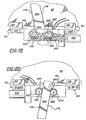
- Figures 11 and 12 illustrate an alternative configuration in which the output shaft 330 of the motor 328 includes dual worm gears 332 engaged with the first and second driven gears 322,324.
- the first and second driven gears 322,324 (shown in Figure 11) are not engaged because each is independently driven by the dual worm gears 332.
- the first and second pinion gears 302,304 (shown in Figure 12) are not engaged because each receives torque from its respective driven gear 322,324. In all other respects, this configuration is the same as discussed above with respect to Figures 7-10.
- a second embodiment is shown in Figures 13-15 and is similar to the first embodiment discussed above. Unlike the first embodiment, however, the racks 170,172 include outwardly facing rows of teeth 174,176 which engage with the first and second pinion gear 302,304 (shown in Figure 15). Guide wheels 341 (shown in phantom in Figures 14 and 15) engage the racks 170,172 to prevent the racks 170,172 from moving out of engagement with the pinion gears 302,304. As shown in Figure 13, the window 52 is positioned as close as possible to the racks 170,172 without physically touching the racks 170,172.
- a motor 340 is integrated within the support bracket 308 and has a dual-ended output shaft 342 including a worm gear 332 at each end of the output shaft 342.
- the worm gears 332 engage with driven gears 322,324 which are, in turn, operatively connected with the pinion gears 302,304.
- the worm gears 332 have opposite helical angles such that the pinion gears 302,304 will rotate in opposing directions as is required to ensure that the pinion gears 302,304 cooperate during vertical movement of the window 52.
- one or both pinion gears 302,304 can be provided with a resilient shock absorber 204 as shown in Figure 10 with respect to the first embodiment.
- the racks 170,172 can alternatively be spaced farther apart such that the pinion gears 302,304, motor 340, and driven gears 322,324 are disposed between the racks 170,172, In this configuration, the teeth 174,176 on the racks 170,172 are located on inwardly facing sides of the racks 170,172.
- the motor 340 is mounted on the support bracket 308 by retaining straps 344.
- the dual-ended output shaft 342 is supported for rotation by bearings 346 and includes a worm gear 332 at each end thereof.
- the worm gears 332 engage with driven gears 322,324 in the same manner as discussed above.
- Seal caps 348 are sonic welded to the support bracket 308 to cover the driven gears 322,324 and prevent entry of water or debris.
- a third embodiment is shown in Figures 17 and 18 and includes parallel racks 170,172 engaged with dual pinion gears 302,304 similar to the first embodiment discussed above.
- the motor 328 includes a single-ended output shaft 330 having worm gears 332 thereon engaged with first and second driven gears 322,324.
- the teeth 174 on the first rack 170 face the same direction as the teeth 176 on the second rack 172.
- the first pinion gear 302 is disposed between the first and second racks 170,172 while the second pinion gear 304 is engaged with the rack teeth 176 on an outwardly facing edge of the second rack 172.
- the third embodiment is identical to the first embodiment.
- a fourth embodiment is shown in Figures 19 and 20 and includes a flexible rack 350 formed from a single, longitudinal rail having first and second rows of teeth 174,176 on opposing sides of the rack 350.
- a motor 328 is provided having a singled-ended output shaft 330 including a pair of worm gears 332 thereon.
- the worm gears 332 engage with driven gears 332,324 which are, in turn, operatively connected to pinion gears 302,304 by central shafts 326.
- the pinion gears 302,304 straddle the rack 350 and engage the rack teeth 174,176.
- Guide members 240 are also provided and prevent the rack 350 from moving in a direction perpendicular to the window 52.
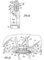
- the object of the present invention is to minimize the space occupied by the various components in all dimensions and, in particular, in the thickness direction of the door. Contrasting this dimension in Figure 3 (Pickles), Figure 4 (Torii et al.), Figure 5 (Fenelon), and Figure 13 (the present invention), we observe that the embodiment of Figure 3 has the largest thickness, the embodiments of Figures 4 and 5 are approximately equal to one another (but smaller than shown in Figure 3), and that the present invention shown in Figure 13 has the smallest thickness. Indeed, the thickness of the embodiment of the present invention is only limited by the thickness of the motor required to drive the unit. It is estimated that a width less than 30 mm is readily achievable. This compares with an estimated 50 mm minimum for previous embodiments. Additionally, the total number of parts has been greatly reduced so that a total weight of less than 1.5 pounds is attainable. This compares favorably with existing weights of arm and sector systems of 6.0 pounds or more.
Landscapes
- Window Of Vehicle (AREA)
- Power-Operated Mechanisms For Wings (AREA)
- Glass Compositions (AREA)
- Paper (AREA)
Claims (9)
- Verschlussanordnung (50), die Folgendes umfasst:dadurch gekennzeichnet, dass der Halter (308) im Wesentlichen innerhalb des Breitenprofils des Motors (328) angeordnet ist, um dadurch den durch den Motor (328) und den Halter (308) eingenommenen Raum zu minimieren.ein Verschlussglied (52);einen mit dem Verschlussglied (52) verbundenen Halter (308);ein durch den Halter (308) gestütztes erstes Ritzel (302);eine mit dem ersten Ritzel (302) in Wirkeingriff stehende erste Zahnstange (170);ein durch den Halter (308) zur Drehung gestütztes getriebenes Zahnrad (322), das mit dem ersten Ritzel (302) in kämmendem Eingriff steht;einen durch den Halter (308) gestützten Motor (328), der eine mit dem angetriebenen Zahnrad (322) in Eingriff stehende Ausgangswelle (330)enthält, wobei der Motor (328) ein Profil in Breitenrichtung definiert;ein durch den Halter (308) gestütztes zweites Ritzel (304), das mit dem ersten Ritzel (302) in kämmendem Eingriff steht;eine mit dem zweiten Ritzel (304) in Wirkeingriff stehende Zahnstange (172), die sich parallel zur ersten Zahnstange (170) erstreckt,
- Verschlussanordnung nach Anspruch 1, dadurch gekennzeichnet, dass die Breite des Halters (308) kleiner gleich einer Breite (WM) des Motors (328) ist.
- Verschlussanordnung nach Anspruch 1, dadurch gekennzeichnet, dass die Breite des Motors (328) kleiner gleich 35 Millimeter ist.
- Verschlussanordnung nach einem der vorhergehenden Ansprüche, dadurch gekennzeichnet, dass die Ausgangswelle (330) im Halter (308) enthalten ist.
- Verschlussanordnung nach einem der vorhergehenden Ansprüche, dadurch gekennzeichnet, dass das angetriebene Zahnrad (322) in einer Kammer (325) im Halter (308) enthalten ist.
- Verschlussanordnung nach einem der vorhergehenden Ansprüche, dadurch gekennzeichnet, dass der Halter (308) modular ist und einen inneren Durchgang (336), durch den sich die Ausgangswelle (330) erstreckt, und eine umschlossene Kammer (325), in der das angetriebene Zahnrad (322) gestützt wird, enthält.
- Verschlussanordnung nach einem der vorhergehenden Ansprüche, dadurch gekennzeichnet, dass die erste Zahnstange (170) auf einer ersten Seite des Verschlussglieds (52) angeordnet ist und der Motor (328) einen sich auf einer zweiten Seite des Verschlussglieds (52) befindenden Schwerpunkt aufweist.
- Verschlussanordnung nach einem der vorhergehenden Ansprüche, dadurch gekennzeichnet, dass das Verschlussglied (52) ein Fahrzeugfenster ist.
- Verschlussanordnung nach einem der vorhergehenden Ansprüche, dadurch gekennzeichnet, dass es weiterhin einen elastischen Stoßdämpfer (204) umfasst, der mit dem ersten Ritzel (302) wirkverbunden ist.
Applications Claiming Priority (3)
| Application Number | Priority Date | Filing Date | Title |
|---|---|---|---|
| US157693 | 1998-09-21 | ||
| US09/157,693 US6216394B1 (en) | 1998-09-21 | 1998-09-21 | Window lift mechanism |
| PCT/US1999/021819 WO2000017476A1 (en) | 1998-09-21 | 1999-09-20 | Window lift mechanism |
Publications (2)
| Publication Number | Publication Date |
|---|---|
| EP1123452A1 EP1123452A1 (de) | 2001-08-16 |
| EP1123452B1 true EP1123452B1 (de) | 2005-08-17 |
Family
ID=22564868
Family Applications (1)
| Application Number | Title | Priority Date | Filing Date |
|---|---|---|---|
| EP99969463A Expired - Lifetime EP1123452B1 (de) | 1998-09-21 | 1999-09-20 | Fensterhebemechanismus |
Country Status (7)
| Country | Link |
|---|---|
| US (1) | US6216394B1 (de) |
| EP (1) | EP1123452B1 (de) |
| AT (1) | ATE302325T1 (de) |
| AU (1) | AU6054299A (de) |
| BR (1) | BR9914014A (de) |
| DE (1) | DE69926777T2 (de) |
| WO (1) | WO2000017476A1 (de) |
Cited By (1)
| Publication number | Priority date | Publication date | Assignee | Title |
|---|---|---|---|---|
| CN111535691A (zh) * | 2020-03-18 | 2020-08-14 | 姜明 | 车窗阻滞压力控制装置及其控制方法 |
Families Citing this family (49)
| Publication number | Priority date | Publication date | Assignee | Title |
|---|---|---|---|---|
| DE19846658A1 (de) * | 1998-10-09 | 2000-04-20 | Metzeler Automotive Profiles | Vorrichtung zum Führen und Dichten einer verfahrbaren Scheibe |
| US6889578B2 (en) * | 2000-01-19 | 2005-05-10 | Stoneridge Control Devices, Inc. | Electro-mechanical actuator |
| US6655092B2 (en) * | 2000-07-24 | 2003-12-02 | Thyssenkrupp Budd Company | Method for fabricating a vehicle door |
| US7824132B1 (en) * | 2000-08-01 | 2010-11-02 | American Piledriving Equipment, Inc. | Automatically adjustable caisson clamp |
| US6648556B1 (en) * | 2000-08-01 | 2003-11-18 | American Piledriving Equipment, Inc. | Automatically adjustable caisson clamp |
| US6896448B1 (en) | 2000-08-01 | 2005-05-24 | American Piledriving Equipment, Inc. | Automatically adjustable caisson clamp |
| US6966149B2 (en) * | 2003-03-27 | 2005-11-22 | Fenelon Paul J | Window bracket for a window lift mechanism |
| US6820369B2 (en) * | 2002-04-18 | 2004-11-23 | Paul J. Fenelon | Window lift mechanism |
| US20040111970A1 (en) * | 2002-04-18 | 2004-06-17 | Fenelon Paul J. | Window lift mechanism |
| CA2430023A1 (en) * | 2002-05-30 | 2003-11-30 | Intier Automotive Closures Inc. | Lead screw window regulator |
| US7694747B1 (en) | 2002-09-17 | 2010-04-13 | American Piledriving Equipment, Inc. | Preloaded drop hammer for driving piles |
| US6866322B2 (en) | 2003-02-06 | 2005-03-15 | Asc Incorporated | Automotive vehicle roof system having a detachable convertible roof |
| DE10320271A1 (de) * | 2003-05-07 | 2004-12-02 | Stegmann Gmbh & Co. Kg | Verstelleinrichtung |
| US7797882B2 (en) * | 2003-05-14 | 2010-09-21 | Ford Global Technologies, Llc | Window positioning apparatus |
| US20050016001A1 (en) * | 2003-06-24 | 2005-01-27 | Milwaukee Electric Tool Corporation | Drive mechanism and power tool |
| US20060249716A1 (en) * | 2003-10-30 | 2006-11-09 | Rincoe Richard G | Method of maneuvering a mechanical arm assembly relative to a base support |
| US20060048452A1 (en) * | 2004-09-03 | 2006-03-09 | Sweeney John A | Flexible mounting bracket for vehicle window panel |
| US7708499B1 (en) * | 2005-01-03 | 2010-05-04 | American Piledriving Equipment, Inc. | Clamp systems and methods for pile drivers and extractors |
| DE102005008437A1 (de) * | 2005-02-24 | 2006-08-31 | Brose Fahrzeugteile Gmbh & Co. Kommanditgesellschaft, Coburg | Fensterheber für ein Kraftfahrzeug |
| US7854571B1 (en) | 2005-07-20 | 2010-12-21 | American Piledriving Equipment, Inc. | Systems and methods for handling piles |
| US8186452B1 (en) | 2005-09-30 | 2012-05-29 | American Piledriving Equipment, Inc. | Clamping systems and methods for piledriving |
| US20070151158A1 (en) * | 2006-01-03 | 2007-07-05 | Fenelon Paul J | Window lift mechanism |
| US7536927B2 (en) * | 2006-06-05 | 2009-05-26 | Brose Fahrzeugteile GmbH & Co. Kommanditgesellschaft, Würzburg | Window lift drive for raising and lowering windows in a vehicle door |
| US20080163553A1 (en) * | 2007-01-09 | 2008-07-10 | Yu-Tsun Liao | Control Device for Controlling Opening and Closing of a Window |
| US8474186B2 (en) * | 2007-03-22 | 2013-07-02 | Dura Operating, Llc | Direct drive slider window assembly |
| US8109352B2 (en) * | 2007-04-24 | 2012-02-07 | Mattel, Inc. | Children's ride-on vehicles with window mechanisms |
| US7967089B2 (en) * | 2007-04-24 | 2011-06-28 | Mattel, Inc. | Children's ride-on vehicles with powered window mechanisms |
| DE102007044350A1 (de) * | 2007-09-17 | 2009-03-19 | Robert Bosch Gmbh | Verstellantrieb |
| US8763719B2 (en) | 2010-01-06 | 2014-07-01 | American Piledriving Equipment, Inc. | Pile driving systems and methods employing preloaded drop hammer |
| DK2542107T3 (en) * | 2010-03-04 | 2014-12-08 | Artisent Llc | Screwdriver for hanging a helmet |
| US8434969B2 (en) | 2010-04-02 | 2013-05-07 | American Piledriving Equipment, Inc. | Internal pipe clamp |
| CA2751959C (en) * | 2010-09-24 | 2018-08-21 | Deere & Company | Multi-worm circle drive gearbox |
| US9091333B2 (en) * | 2011-01-05 | 2015-07-28 | General Dynamics—OTS, Inc. | Loading machine for feeding a receiver |
| USD681707S1 (en) | 2011-03-03 | 2013-05-07 | Artisent, Llc | Worm gear adjuster |
| US9249551B1 (en) | 2012-11-30 | 2016-02-02 | American Piledriving Equipment, Inc. | Concrete sheet pile clamp assemblies and methods and pile driving systems for concrete sheet piles |
| US9371624B2 (en) | 2013-07-05 | 2016-06-21 | American Piledriving Equipment, Inc. | Accessory connection systems and methods for use with helical piledriving systems |
| EP2921694B1 (de) * | 2014-03-18 | 2019-06-05 | Cascade Drives AB | Getriebeanordnung |
| CN105064845B (zh) * | 2015-08-13 | 2016-09-14 | 宁波润佳汽车安全系统有限公司 | 用于车窗升降的装置 |
| US10273646B2 (en) | 2015-12-14 | 2019-04-30 | American Piledriving Equipment, Inc. | Guide systems and methods for diesel hammers |
| US10538892B2 (en) | 2016-06-30 | 2020-01-21 | American Piledriving Equipment, Inc. | Hydraulic impact hammer systems and methods |
| US10370887B2 (en) * | 2016-07-25 | 2019-08-06 | Rick K. Lange | Hidden motorized system for opening and closing a window |
| US10718150B2 (en) * | 2017-07-03 | 2020-07-21 | Hall Labs Llc | Gear-driven automated window or door system |
| DE102018119474A1 (de) * | 2018-08-10 | 2020-02-13 | Dr. Ing. H.C. F. Porsche Aktiengesellschaft | Fensterheberanordnung |
| JP7088455B2 (ja) * | 2019-01-08 | 2022-06-21 | 三井金属アクト株式会社 | 車両サイドドアの開閉装置 |
| US11318818B2 (en) * | 2019-02-15 | 2022-05-03 | Hi-Lex Controls, Inc. | Window regulator with power supply connection for electrical device on movable glass |
| US11603697B2 (en) * | 2020-04-16 | 2023-03-14 | Hall Labs Llc | Automated window mechanisms with telescoping arm extensions |
| US11339601B2 (en) | 2020-07-27 | 2022-05-24 | Rivian Ip Holdings, Llc | Power pocket sliding door |
| CA3153781A1 (en) | 2021-03-31 | 2022-09-30 | American Piledriving Equipment, Inc. | Segmented ram systems and methods for hydraulic impact hammers |
| US12606972B2 (en) | 2024-02-07 | 2026-04-21 | American Piledriving Equipment, Inc. | Variable moment vibratory systems and methods |
Family Cites Families (45)
| Publication number | Priority date | Publication date | Assignee | Title |
|---|---|---|---|---|
| US548695A (en) | 1895-10-29 | Half to charles j | ||
| US1356123A (en) | 1920-02-11 | 1920-10-19 | Thomas H Bell | Window-closure device |
| US1939159A (en) | 1930-08-05 | 1933-12-12 | Equipment & Supply Co Inc | Hospital door and the like |
| US1903358A (en) | 1931-06-24 | 1933-04-04 | Briggs & Stratton Corp | Window regulator |
| US1937662A (en) | 1931-10-08 | 1933-12-05 | Briggs & Stratton Corp | Window regulator |
| US2293968A (en) | 1941-05-05 | 1942-08-25 | Aresee Company Inc | Cam operated electrical switch |
| US2336530A (en) | 1941-05-05 | 1943-12-14 | Aresee Company Inc | Floating drive mechanism for automobile door windows |
| US2365454A (en) | 1942-05-21 | 1944-12-19 | Aresee Company Inc | Automobile window control |
| US2531116A (en) | 1945-09-08 | 1950-11-21 | Donoghue Harold | Rain operated automatic window closer |
| GB851436A (en) | 1959-05-01 | 1960-10-19 | Ford Motor Co | Improvements in or relating to motor vehicle window regulators |
| US3263367A (en) | 1964-05-08 | 1966-08-02 | Gen Motors Corp | Closure regulator means |
| FR1425449A (fr) | 1964-12-08 | 1966-01-24 | Citroen Sa Andre | Mécanisme de lève-glace pour portière de véhicule |
| DE1931471C3 (de) | 1969-06-20 | 1974-04-11 | H.T. Golde Gmbh, 6000 Frankfurt | Fensterheber mit Gewichtsausgleichvorrichtung für Schiebefenster, insbesondere von Kraftfahrzeugen |
| DE2150332A1 (de) | 1970-10-10 | 1972-04-13 | Luigi Binetti | Hubvorrichtung fuer Glasscheiben,insbesondere an Tueren fuer Kraftfahrzeuge |
| DE2217784C3 (de) | 1972-04-13 | 1980-07-03 | Rockwell Golde Gmbh, 6000 Frankfurt | Fensterheber für Kraftfahrzeuge |
| DE2544174C2 (de) | 1975-10-03 | 1983-04-21 | Keiper Automobiltechnik Gmbh & Co Kg, 5630 Remscheid | Stellgetriebe mit einem einen Zahnbogen aufweisenden Hubhebel |
| US4182078A (en) * | 1978-02-13 | 1980-01-08 | Merit Plastics, Inc. | Window regulator and drive assembly |
| US4167834A (en) | 1978-02-15 | 1979-09-18 | Ferro Manufacturing Corporation | Power window mechanism |
| US4170847A (en) | 1978-06-01 | 1979-10-16 | Ferro Manufacturing Corporation | Tailgate window regulator |
| DE2841440A1 (de) | 1978-09-22 | 1980-04-03 | Kaufmann Metallwerk J C F | Kurbelmechanik zum oeffnen und schliessen eines fensters |
| JPS5761062U (de) | 1980-09-29 | 1982-04-10 | ||
| US4400913A (en) | 1981-06-15 | 1983-08-30 | Chrysler Corporation | Counterbalance pinion for vehicle window regulator |
| DE3309427A1 (de) * | 1982-03-18 | 1983-10-06 | Valeo | Betaetigungsvorrichtung fuer eine kupplung, ein regelgetriebe, eine bremse, oder aehnliches |
| DE3243123C2 (de) | 1982-11-22 | 1986-10-16 | Brose Fahrzeugteile GmbH & Co KG, 8630 Coburg | Fensterheber, insbesondere für Kraftfahrzeuge |
| FR2550267B1 (fr) | 1983-08-04 | 1985-11-15 | Marchal Equip Auto | Dispositif de manoeuvre d'un organe, tel qu'une glace de portiere ou un toit ouvrant, notamment pour vehicule automobile |
| DE3545856C1 (en) | 1985-12-23 | 1987-01-08 | Daimler Benz Ag | Adjustable connection of a retaining rail and of a basic plate |
| DE3727153A1 (de) | 1987-08-14 | 1989-02-23 | Kuester & Co Gmbh | Bowdenzug-fensterheber |
| US4908988A (en) * | 1988-04-25 | 1990-03-20 | Asmo Co., Ltd. | Self-driving closure device |
| JP2507536B2 (ja) | 1988-04-25 | 1996-06-12 | アスモ株式会社 | 手動式ウインドウレギュレ―タ |
| KR910005898Y1 (ko) * | 1988-10-07 | 1991-08-12 | 김영철 | 자동차용 차양 장치의 구동 장치 |
| DE3903556C2 (de) | 1989-02-07 | 1993-10-14 | Kuester & Co Gmbh | Mitnehmer eines Bowdenzug-Fensterhebers |
| US4967510A (en) | 1989-07-31 | 1990-11-06 | Amso Co., Ltd. | Closure device |
| FR2650647B1 (fr) | 1989-08-07 | 1997-07-18 | Mitsuba Electric Mfg Co | Dispositif a vis sans fin |
| DE4005759A1 (de) | 1990-02-23 | 1991-08-29 | Helmut Coobs | Elektrischer fensterheber fuer kraftfahrzeuge und fahrzeuge |
| US5058322A (en) | 1990-08-06 | 1991-10-22 | Ford Motor Company | Movable window assembly |
| FR2693568B1 (fr) | 1992-07-10 | 1994-09-30 | Rockwell Abs France | Dispositif de sécurité pour ouvrants électriques de véhicule, notamment lève-vitre et toits ouvrants, et ouvrant incorporant ce dispositif. |
| DE9209929U1 (de) | 1992-07-23 | 1992-09-24 | Siemens AG, 8000 München | Fensterheber-Antriebseinheit |
| DE4340013A1 (de) * | 1993-11-24 | 1995-06-01 | Brose Fahrzeugteile | Elektrisch angetriebene Verstellvorrichtung für Fensterscheiben oder Schiebedächer von Kraftfahrzeugen |
| WO1997037099A2 (en) | 1996-03-29 | 1997-10-09 | Excel Industries, Inc. | Window regulator with improved glider assembly |
| US5794478A (en) | 1996-05-21 | 1998-08-18 | Chin-Yun Huang | Transmitting chain for an automobile electric window |
| DE29613322U1 (de) | 1996-08-01 | 1996-10-24 | Huang, Chin-Yun, Yung-Kang, Tainan | Übertragungsvorrichtung für elektrisch betätigbare Fenster in Kraftfahrzeugen |
| US5806244A (en) | 1997-05-30 | 1998-09-15 | Ut Automotive Dearborn, Inc. | Single drive dual rack and pinion window regulator |
| US6389753B1 (en) | 1996-12-09 | 2002-05-21 | Paul J. Fenelon | Window lift mechanism |
| DE19703720A1 (de) | 1997-01-22 | 1998-07-23 | Brose Fahrzeugteile | Fensterscheibe aus Kunststoff für eine Kraftfahrzeugtür und Fensterheber zum Transport der Fensterscheibe |
| US5836205A (en) * | 1997-02-13 | 1998-11-17 | Steven M. Meyer | Linear actuator mechanism |
-
1998
- 1998-09-21 US US09/157,693 patent/US6216394B1/en not_active Expired - Fee Related
-
1999
- 1999-09-20 WO PCT/US1999/021819 patent/WO2000017476A1/en not_active Ceased
- 1999-09-20 AT AT99969463T patent/ATE302325T1/de not_active IP Right Cessation
- 1999-09-20 DE DE69926777T patent/DE69926777T2/de not_active Expired - Fee Related
- 1999-09-20 AU AU60542/99A patent/AU6054299A/en not_active Abandoned
- 1999-09-20 EP EP99969463A patent/EP1123452B1/de not_active Expired - Lifetime
- 1999-09-20 BR BR9914014-4A patent/BR9914014A/pt not_active IP Right Cessation
Cited By (1)
| Publication number | Priority date | Publication date | Assignee | Title |
|---|---|---|---|---|
| CN111535691A (zh) * | 2020-03-18 | 2020-08-14 | 姜明 | 车窗阻滞压力控制装置及其控制方法 |
Also Published As
| Publication number | Publication date |
|---|---|
| EP1123452A1 (de) | 2001-08-16 |
| AU6054299A (en) | 2000-04-10 |
| DE69926777D1 (de) | 2005-09-22 |
| BR9914014A (pt) | 2004-06-29 |
| DE69926777T2 (de) | 2006-05-18 |
| US6216394B1 (en) | 2001-04-17 |
| ATE302325T1 (de) | 2005-09-15 |
| WO2000017476A1 (en) | 2000-03-30 |
Similar Documents
| Publication | Publication Date | Title |
|---|---|---|
| US6216394B1 (en) | Window lift mechanism | |
| EP4494934B1 (de) | Langschienenanordnung mit internem leistungsantriebssystem | |
| US6820369B2 (en) | Window lift mechanism | |
| US5537782A (en) | Electrically-operated displacement device for windows or sliding roofs of motor vehicles | |
| US6966149B2 (en) | Window bracket for a window lift mechanism | |
| JPH0737023Y2 (ja) | パワーウインド装置 | |
| US5309677A (en) | Electrically operated vehicle window | |
| US7810282B2 (en) | Belt-driven rack gear power sliding door | |
| EP1015723B1 (de) | Fensterheber | |
| CN115680430B (zh) | 一种单电机控制滑门系统及车辆 | |
| US6073395A (en) | Window lift mechanism | |
| US20040111970A1 (en) | Window lift mechanism | |
| US4986029A (en) | Window regulator for vehicle doors | |
| CN1294070C (zh) | 用于电梯门的紧凑驱动装置及其支承过梁 | |
| US7578094B2 (en) | Drive unit for power operated vehicle closure | |
| CN220014922U (zh) | 带防夹门帘的物流柜 | |
| CN2813833Y (zh) | 汽车中滑门的电动传动装置 | |
| US20230304350A1 (en) | Power side door actuator having rack and pinion drive | |
| JP2002509592A (ja) | 窓昇降装置 | |
| CN216731602U (zh) | 一种连续稳定的汽车前保险杠装配设备 | |
| CN222633082U (zh) | 一种隐形齿轮齿条传动汽车电动滑移门 | |
| CN217296882U (zh) | 一种新型电梯机械式自动门机 | |
| CN218438975U (zh) | 滑动变轨升降窗 | |
| EP1359277B1 (de) | Motorbetriebene Antriebsvorrichtung für ein Schliesselement eines Fahrzeuges | |
| AU2019205976B2 (en) | Drive unit for a slide-out room |
Legal Events
| Date | Code | Title | Description |
|---|---|---|---|
| PUAI | Public reference made under article 153(3) epc to a published international application that has entered the european phase |
Free format text: ORIGINAL CODE: 0009012 |
|
| 17P | Request for examination filed |
Effective date: 20010418 |
|
| AK | Designated contracting states |
Kind code of ref document: A1 Designated state(s): AT BE CH CY DE DK ES FI FR GB GR IE IT LI LU MC NL PT SE |
|
| AX | Request for extension of the european patent |
Free format text: AL;LT;LV;MK;RO;SI |
|
| 17Q | First examination report despatched |
Effective date: 20040823 |
|
| GRAP | Despatch of communication of intention to grant a patent |
Free format text: ORIGINAL CODE: EPIDOSNIGR1 |
|
| GRAS | Grant fee paid |
Free format text: ORIGINAL CODE: EPIDOSNIGR3 |
|
| GRAA | (expected) grant |
Free format text: ORIGINAL CODE: 0009210 |
|
| AK | Designated contracting states |
Kind code of ref document: B1 Designated state(s): AT BE CH CY DE DK ES FI FR GB GR IE IT LI LU MC NL PT SE |
|
| AX | Request for extension of the european patent |
Extension state: MK |
|
| PG25 | Lapsed in a contracting state [announced via postgrant information from national office to epo] |
Ref country code: NL Free format text: LAPSE BECAUSE OF FAILURE TO SUBMIT A TRANSLATION OF THE DESCRIPTION OR TO PAY THE FEE WITHIN THE PRESCRIBED TIME-LIMIT Effective date: 20050817 Ref country code: LI Free format text: LAPSE BECAUSE OF FAILURE TO SUBMIT A TRANSLATION OF THE DESCRIPTION OR TO PAY THE FEE WITHIN THE PRESCRIBED TIME-LIMIT Effective date: 20050817 Ref country code: FI Free format text: LAPSE BECAUSE OF FAILURE TO SUBMIT A TRANSLATION OF THE DESCRIPTION OR TO PAY THE FEE WITHIN THE PRESCRIBED TIME-LIMIT Effective date: 20050817 Ref country code: CH Free format text: LAPSE BECAUSE OF FAILURE TO SUBMIT A TRANSLATION OF THE DESCRIPTION OR TO PAY THE FEE WITHIN THE PRESCRIBED TIME-LIMIT Effective date: 20050817 Ref country code: BE Free format text: LAPSE BECAUSE OF FAILURE TO SUBMIT A TRANSLATION OF THE DESCRIPTION OR TO PAY THE FEE WITHIN THE PRESCRIBED TIME-LIMIT Effective date: 20050817 Ref country code: AT Free format text: LAPSE BECAUSE OF FAILURE TO SUBMIT A TRANSLATION OF THE DESCRIPTION OR TO PAY THE FEE WITHIN THE PRESCRIBED TIME-LIMIT Effective date: 20050817 |
|
| REG | Reference to a national code |
Ref country code: GB Ref legal event code: FG4D |
|
| REG | Reference to a national code |
Ref country code: CH Ref legal event code: EP |
|
| PG25 | Lapsed in a contracting state [announced via postgrant information from national office to epo] |
Ref country code: IE Free format text: LAPSE BECAUSE OF NON-PAYMENT OF DUE FEES Effective date: 20050920 Ref country code: CY Free format text: LAPSE BECAUSE OF FAILURE TO SUBMIT A TRANSLATION OF THE DESCRIPTION OR TO PAY THE FEE WITHIN THE PRESCRIBED TIME-LIMIT Effective date: 20050920 |
|
| REG | Reference to a national code |
Ref country code: IE Ref legal event code: FG4D |
|
| REF | Corresponds to: |
Ref document number: 69926777 Country of ref document: DE Date of ref document: 20050922 Kind code of ref document: P |
|
| PG25 | Lapsed in a contracting state [announced via postgrant information from national office to epo] |
Ref country code: MC Free format text: LAPSE BECAUSE OF NON-PAYMENT OF DUE FEES Effective date: 20050930 |
|
| PG25 | Lapsed in a contracting state [announced via postgrant information from national office to epo] |
Ref country code: LU Free format text: LAPSE BECAUSE OF NON-PAYMENT OF DUE FEES Effective date: 20051017 |
|
| PG25 | Lapsed in a contracting state [announced via postgrant information from national office to epo] |
Ref country code: SE Free format text: LAPSE BECAUSE OF FAILURE TO SUBMIT A TRANSLATION OF THE DESCRIPTION OR TO PAY THE FEE WITHIN THE PRESCRIBED TIME-LIMIT Effective date: 20051117 Ref country code: GR Free format text: LAPSE BECAUSE OF FAILURE TO SUBMIT A TRANSLATION OF THE DESCRIPTION OR TO PAY THE FEE WITHIN THE PRESCRIBED TIME-LIMIT Effective date: 20051117 Ref country code: DK Free format text: LAPSE BECAUSE OF FAILURE TO SUBMIT A TRANSLATION OF THE DESCRIPTION OR TO PAY THE FEE WITHIN THE PRESCRIBED TIME-LIMIT Effective date: 20051117 |
|
| PG25 | Lapsed in a contracting state [announced via postgrant information from national office to epo] |
Ref country code: ES Free format text: LAPSE BECAUSE OF FAILURE TO SUBMIT A TRANSLATION OF THE DESCRIPTION OR TO PAY THE FEE WITHIN THE PRESCRIBED TIME-LIMIT Effective date: 20051128 |
|
| PG25 | Lapsed in a contracting state [announced via postgrant information from national office to epo] |
Ref country code: PT Free format text: LAPSE BECAUSE OF FAILURE TO SUBMIT A TRANSLATION OF THE DESCRIPTION OR TO PAY THE FEE WITHIN THE PRESCRIBED TIME-LIMIT Effective date: 20060117 |
|
| NLV1 | Nl: lapsed or annulled due to failure to fulfill the requirements of art. 29p and 29m of the patents act | ||
| REG | Reference to a national code |
Ref country code: CH Ref legal event code: PL |
|
| ET | Fr: translation filed | ||
| REG | Reference to a national code |
Ref country code: IE Ref legal event code: MM4A |
|
| PLBE | No opposition filed within time limit |
Free format text: ORIGINAL CODE: 0009261 |
|
| STAA | Information on the status of an ep patent application or granted ep patent |
Free format text: STATUS: NO OPPOSITION FILED WITHIN TIME LIMIT |
|
| 26N | No opposition filed |
Effective date: 20060518 |
|
| PGFP | Annual fee paid to national office [announced via postgrant information from national office to epo] |
Ref country code: FR Payment date: 20060908 Year of fee payment: 8 |
|
| PGFP | Annual fee paid to national office [announced via postgrant information from national office to epo] |
Ref country code: DE Payment date: 20060914 Year of fee payment: 8 |
|
| PGFP | Annual fee paid to national office [announced via postgrant information from national office to epo] |
Ref country code: GB Payment date: 20060920 Year of fee payment: 8 |
|
| PGFP | Annual fee paid to national office [announced via postgrant information from national office to epo] |
Ref country code: IT Payment date: 20060930 Year of fee payment: 8 |
|
| GBPC | Gb: european patent ceased through non-payment of renewal fee |
Effective date: 20070920 |
|
| PG25 | Lapsed in a contracting state [announced via postgrant information from national office to epo] |
Ref country code: DE Free format text: LAPSE BECAUSE OF NON-PAYMENT OF DUE FEES Effective date: 20080401 |
|
| REG | Reference to a national code |
Ref country code: FR Ref legal event code: ST Effective date: 20080531 |
|
| PG25 | Lapsed in a contracting state [announced via postgrant information from national office to epo] |
Ref country code: FR Free format text: LAPSE BECAUSE OF NON-PAYMENT OF DUE FEES Effective date: 20071001 |
|
| PG25 | Lapsed in a contracting state [announced via postgrant information from national office to epo] |
Ref country code: GB Free format text: LAPSE BECAUSE OF NON-PAYMENT OF DUE FEES Effective date: 20070920 |
|
| PG25 | Lapsed in a contracting state [announced via postgrant information from national office to epo] |
Ref country code: IT Free format text: LAPSE BECAUSE OF NON-PAYMENT OF DUE FEES Effective date: 20070920 |